EP1314857B1 - Controlling turbine blade tip clearance according to thermal growth model - Google Patents
Controlling turbine blade tip clearance according to thermal growth model Download PDFInfo
- Publication number
- EP1314857B1 EP1314857B1 EP02258021A EP02258021A EP1314857B1 EP 1314857 B1 EP1314857 B1 EP 1314857B1 EP 02258021 A EP02258021 A EP 02258021A EP 02258021 A EP02258021 A EP 02258021A EP 1314857 B1 EP1314857 B1 EP 1314857B1
- Authority
- EP
- European Patent Office
- Prior art keywords
- turbomachine
- determining
- components
- component
- thermal growth
- Prior art date
- Legal status (The legal status is an assumption and is not a legal conclusion. Google has not performed a legal analysis and makes no representation as to the accuracy of the status listed.)
- Expired - Lifetime
Links
- 230000012010 growth Effects 0.000 title claims description 92
- 239000012530 fluid Substances 0.000 claims description 49
- 238000012546 transfer Methods 0.000 claims description 36
- 238000000034 method Methods 0.000 claims description 26
- 239000000463 material Substances 0.000 claims description 16
- 230000008859 change Effects 0.000 claims description 8
- 230000015572 biosynthetic process Effects 0.000 claims description 7
- 230000004044 response Effects 0.000 claims description 7
- 238000003786 synthesis reaction Methods 0.000 claims description 7
- 238000012360 testing method Methods 0.000 claims description 5
- 238000000611 regression analysis Methods 0.000 claims description 4
- 238000005259 measurement Methods 0.000 claims 7
- 238000001816 cooling Methods 0.000 description 10
- 230000014509 gene expression Effects 0.000 description 8
- 230000008569 process Effects 0.000 description 8
- 230000008901 benefit Effects 0.000 description 7
- 230000001276 controlling effect Effects 0.000 description 7
- 238000004364 calculation method Methods 0.000 description 5
- 238000013178 mathematical model Methods 0.000 description 5
- 238000004422 calculation algorithm Methods 0.000 description 4
- 230000002596 correlated effect Effects 0.000 description 4
- 230000000694 effects Effects 0.000 description 4
- 239000000446 fuel Substances 0.000 description 4
- 230000001052 transient effect Effects 0.000 description 4
- 238000009472 formulation Methods 0.000 description 3
- 239000000203 mixture Substances 0.000 description 3
- 238000011161 development Methods 0.000 description 2
- 239000002184 metal Substances 0.000 description 2
- 206010017577 Gait disturbance Diseases 0.000 description 1
- 238000013459 approach Methods 0.000 description 1
- 238000002485 combustion reaction Methods 0.000 description 1
- 238000012937 correction Methods 0.000 description 1
- 230000003247 decreasing effect Effects 0.000 description 1
- 238000009795 derivation Methods 0.000 description 1
- 238000013461 design Methods 0.000 description 1
- 238000004146 energy storage Methods 0.000 description 1
- 238000005057 refrigeration Methods 0.000 description 1
Images


Classifications
-
- F—MECHANICAL ENGINEERING; LIGHTING; HEATING; WEAPONS; BLASTING
- F01—MACHINES OR ENGINES IN GENERAL; ENGINE PLANTS IN GENERAL; STEAM ENGINES
- F01D—NON-POSITIVE DISPLACEMENT MACHINES OR ENGINES, e.g. STEAM TURBINES
- F01D11/00—Preventing or minimising internal leakage of working-fluid, e.g. between stages
- F01D11/08—Preventing or minimising internal leakage of working-fluid, e.g. between stages for sealing space between rotor blade tips and stator
- F01D11/14—Adjusting or regulating tip-clearance, i.e. distance between rotor-blade tips and stator casing
- F01D11/20—Actively adjusting tip-clearance
- F01D11/24—Actively adjusting tip-clearance by selectively cooling-heating stator or rotor components
-
- G—PHYSICS
- G05—CONTROLLING; REGULATING
- G05B—CONTROL OR REGULATING SYSTEMS IN GENERAL; FUNCTIONAL ELEMENTS OF SUCH SYSTEMS; MONITORING OR TESTING ARRANGEMENTS FOR SUCH SYSTEMS OR ELEMENTS
- G05B17/00—Systems involving the use of models or simulators of said systems
- G05B17/02—Systems involving the use of models or simulators of said systems electric
Definitions
- the present invention generally relates to a system and method of clearance control of motor or engine fan blades, and more particularly relates to a system and method of determining thermal growth of motor or engine parts to thereupon control the clearance of motor or engine fan blades.
- Imperfect control of the clearance between a turbine engine fan blade and case results in either the clearance being too loose or the clearance being too tight resulting in excessive rubs. In either instance, imperfect clearance results in loss of performance (e.g. engine efficiency, thrust) and/or violation of the engine operating limits (e.g. exhaust gas temperature overshoot) and/or reduced compressor stability. Standard practice has been to design a clearance control system to prefer loose clearance over tight clearance which may also result in damage to the blades and case.
- Some engines such as, for example, the PW4000 use an open loop clearance control system that sacrifices significant performance in comparison with a "perfect" clearance control system.
- Other engines such as, for example, the V2500 use a closed loop system that relies on crudely modeled clearances and therefore sacrifices less performance, but still falls short of ideal clearance control.
- the principal difficulty in modeling clearances for a closed loop system resides in modeling the thermal growths of the engine components, not in modeling the mechanical strains which are relatively easy to calculate.
- Thermal growths are far more difficult to model because the physical configurations of the engine components and the multiple time varying influences to which those components are subjected (i.e., throttle transients, multiple fluid streams of different and time varying temperatures, flow rates, etc.) complicate the problem of modeling the heat transfer and energy storage phenomenon.
- a method of controlling clearance in a turbomachine between blades and a wall adjacent to and opposing tips of the blades includes adjusting air flow adjacent to the wall in response to the difference between the desired clearance and the actual clearance. Due to lack of suitable sensors, an accurate and reliable estimate of the actual clearance is made with a real time, mathematical model running, on-board engine controller. As part of the clearance calculation the subject model computes thermal growth of the turbomachine components and their subcomponents with a difference equation derived from a closed form solution to the 1 st order differential equation obtained through the application of the 1 st law of thermodynamics. The component is treated as being made of uniform material with given average specific heat and mass while at uniform temperature throughout the volume.
- the heat transfer phenomenon is modeled as a sum of a finite number of heat transfer processes taking place over the entire area of the component interface with the known gas turbine fluid streams. Each heat transfer process is characterized by a local average heat transfer coefficient, contact surface area and fluid temperature.
- the solution is defined over a time step of the control software assuming either step or ramp input and is expressed in terms of equivalent time constant, steady state growth and a set of approximating coefficients.
- the steady state growth is calculated as a weighted average of the growths due to thermal exchange with fluid streams of varying temperatures, flow rates and thermo-physical properties. The weighting is accomplished with performance parameters that are first formed as functions of the local fluid stream area of contact, the local heat transfer coefficient, the total component mass and the component average specific heat.
- the performance parameters are correlated with the measured and otherwise synthesized engine characteristics such as shaft speeds, pressures and temperatures. Finally, the inverse of the equivalent time constant is calculated as a sum of the same performance parameters.
- a system for controlling clearance in a turbomachine between blades and a wall adjacent to and opposing tips of the blades includes adjusting air flow adjacent to the wall in response to the difference between the desired clearance and the actual clearance. Due to lack of suitable sensors, an accurate and reliable estimate of the actual clearance is made with a real time, mathematical model running, on-board engine controller. As part of the clearance calculation the subject model computes thermal growth of the turbomachine components with a difference equation derived from a closed form solution to the 1 st order differential equation obtained through the application of the 1 st law of thermodynamics. The component is treated as being made of uniform material with given average specific heat and mass while at uniform temperature throughout the volume.
- the heat transfer phenomenon is modeled as a sum of a finite number of heat transfer processes taking place over the entire area of the component interface with the known gas turbine fluid streams. Each heat transfer process is characterized by a local average heat transfer coefficient, contact surface area and fluid temperature.
- the solution is defined over a time step of the control software assuming either step or ramp input and is expressed in terms of equivalent time constant, steady state growth and a set of approximating coefficients.
- the steady state growth is calculated as a weighted average of the growths due to thermal exchange with fluid streams of varying temperatures, flow rates and thermo-physical properties. The weighting is accomplished with performance parameters that are first formed as functions of the local fluid stream area of contact, the local heat transfer coefficient, the total component mass and the component average specific heat.
- the performance parameters are correlated with the measured and otherwise synthesized engine characteristics such as shaft speeds, pressures and temperatures. Finally, the inverse of the equivalent time constant is calculated as a sum of the same performance parameters.
- a gas turbine engine system comprises an engine including case and disk with blades rotatable within the case.
- Means are provided for controlling clearance in a turbomachine between blades and a wall adjacent to and opposing tips of the blades to adjust air flow adjacent to the wall in response to the difference between the desired clearance and the actual clearance. Due to lack of suitable sensors, an accurate and reliable estimate of the actual clearance is made with a real time, mathematical model running, on-board engine controller.
- the subject model computes thermal growth of the turbomachine components with a difference equation derived from a closed form solution to the 1 st order differential equation obtained through the application of the 1 st law of thermodynamics.
- the component is treated as being made of uniform material with given average specific heat and mass while at uniform temperature throughout the volume.
- the heat transfer phenomenon is modeled as a sum of finite number of heat transfer processes taking place over the entire area of the component interface with the known gas turbine fluid streams. Each heat transfer process is characterized by a local average heat transfer coefficient, contact surface area and fluid temperature.
- the solution is defined over a time step of the control software assuming either step or ramp input and is expressed in terms of equivalent time constant, steady state growth and a set of approximating coefficients.
- the steady state growth is calculated as a weighted average of the growths due to thermal exchange with fluid streams of varying temperatures, flow rates and thermo-physical properties.
- the weighting is accomplished with performance parameters that are first formed as functions of the local fluid stream area of contact, the local heat transfer coefficient, the total component mass and the component average specific heat. Then, recognizing that these characteristics are impractical to define for a specific component, the performance parameters are correlated with the measured and otherwise synthesized engine characteristics such as shaft speeds, pressures and temperatures. Finally, the inverse of the equivalent time constant is calculated as a sum of the same performance parameters.
- An advantage of the present invention in its preferred embodiment at least is that the thermal growths of turbomachine components and its sub-components may be accurately and reliably determined for subsequent use in the estimation of actual clearance of a turbomachine which is a required element in closed loop active clearance control schemes such as one typically employed in a turbine case cooling.
- a second advantage of the present invention in its preferred embodiment at least is that an accurate numerical technique, namely a closed form solution to the governing differential equation applied over time step of control software is employed to implement 1 st order dynamics of the thermal growth.
- a third advantage of the present invention in its preferred embodiment at least is that the effect of multiple fluid streams is accounted for in the calculation of both steady state and transient characteristics of the thermal growth.
- a fourth advantage of the present invention in its preferred embodiment at least is the allowance of finite order dynamics to be implemented as the sum of 1 st order dynamic elements.
- the component can be subdivided into a finite number of sub-components each modeled with a 1 st order dynamic element.
- a fifth advantage of the present invention in its preferred embodiment at least is the use of approximating coefficients to allow for calibration against high fidelity models and test data, and to facilitate the model traceability to a specific set of turbomachine hardware which may be changing through the operational life of the machine.
- a sixth advantage of the present invention in its preferred embodiment at least is that the physics-based model increases chances of sensible results outside the machine operating envelope.
- a gas turbine engine and system for controlling clearance between blades and the engine case is generally designated by the reference number 10.
- the present invention will be explained primarily with respect to a gas turbine engine, it should be understood that the present invention may be employed with other types of systems employing turbomachinery such as, for example, refrigeration systems without departing from the scope of the present invention.
- the turbine engine includes a fan 18, a low pressure compressor 20, a high pressure compressor 22, a burner 24 for injecting fuel into an air stream, a high pressure turbine 26 and a low pressure turbine 28.
- a system 30 for controlling clearance includes a valve 32, such as a butterfly valve, that is continuously adjustable from a fully closed position to a fully open position for diverting an auxiliary or cooling air flow, indicated by the arrows 33, 33, from a fan stream onto an engine case 50 for cooling the engine case in order to provide a desired clearance between the case and the engine blades.
- the high pressure compressor 22 and the high pressure turbine 26 are on a first spool (high spool) as schematically illustrated by line 37 connecting the high pressure compressor and the high pressure turbine.
- the fan 18, the low pressure compressor 20, and the low pressure turbine 28 are on a second spool (low spool) as schematically illustrated by line 39 connecting the low pressure compressor and the low pressure turbine.
- the high pressure turbine 26 includes a disk 41 and a blade 43. A tip 45 of the blade and the opposing case or wall 50 cooperate to define a clearance distance 47 therebetween to be adjusted by controllably diverting a cooling air flow 33 of desired intensity from the fan stream.
- Engine sensors 38 include high and low spool speed, and burner pressure.
- a controller 40 has an input 42 coupled to the sensors 38. Residing in the controller 40 is the control software that includes logic that determines desired high pressure turbine clearance, the mathematical model that calculates actual clearance and the control algorithm that determines angle of the valve 32 in response to the difference between the desired and the actual clearance.
- a motor 44 preferably a dual-channel torque motor, is controllably coupled to the controller 40.
- An actuator 46 such as a piston actuator, is drivingly coupled to an output of the motor 44.
- the valve 32 is controllably coupled to the actuator 46.
- a gas turbine engine operates by receiving a primary air flow, indicated by the arrows 48, 48, at its inlet end 14 at a relative velocity equal to the flight speed.
- a primary air flow indicated by the arrows 48, 48
- the velocity of the primary air flow 48 is decreased and its pressure is increased.
- the air flow pressure is further increased as it moves through the compressors 20 and 22.
- a steady fuel stream is injected into the primary air flow 48 and combustion of the fuel occurs continuously.
- the hot gas under high pressure moves through nozzles of the turbines 26 and 28 which direct it at high velocity against buckets on turbine wheels to cause the wheels to rotate.
- the turbine wheels drive the compressors to which they are connected through a shaft After the hot gas leaves the turbines 26 and 28, the gas is at a high temperature and at a pressure significantly above atmospheric pressure. The hot gas is discharged at the outlet end 16 of the engine 12 at a high velocity so as to produce thrust.
- the determination of thermal growth for controlling clearance in accordance with the present invention will now be more fully explained.
- the total radial growth may be understood as a sum of the growths because of thermal and mechanical causes.
- the main difficulty in creating a radial growth calculation technique lies in formulating and solving a differential equation governing radial growth because of thermal expansion of the turbo-machine component material.
- the formulation must properly describe a component of complex geometry (e.g., turbine case) exchanging heat with several fluid streams of widely varying temperatures and flow rates.
- thermodynamics is formulated for a closed system that includes turbomachine component subjected to heat transfer with the surrounding fluid flows.
- the temperature is assumed to be uniform throughout the turbomachine component.
- the system is assumed to be interfaced with a finite number of gas flows of specified temperature.
- This formulation leads to a first order differential equation in terms of the component material temperature.
- the equation is further simplified by defining an equivalent fluid temperature and time constant.
- a generalized transfer function is derived and a closed form solution for turbomachine component material average temperature for step and ramp changes in equivalent fluid temperature is then obtained by means of Laplace transform.
- the solutions for turbomachine component temperature is transformed into the one for thermal growth based on linear dependency between the two.
- a difference equation for implementation in the controller is formed.
- a turbomachine component has uniform density and material temperature.
- the subject turbomachine component (hereafter referred to simply as the component) is exchanging heat with a finite number of fluid flows each interfacing with the portion of the metal surface.
- T m ( t ) T eq ( 0 ) + t ⁇ k rate + [ T m ( 0 ) ⁇ T eq ( 0 ) + k rate ⁇ eq ] e ⁇ t ⁇ eq
- k rate T eq ( t ) ⁇ T eq ( 0 ) d t
- Equations (6) and (8) can now be transformed into expressions for the component radial growth because of thermal expansion of the component material.
- the component temperature is replaced directly with thermal growth (dR).
- the equivalent fluid temperature represents the driving force of the growth process and is replaced with what is referred to as steady state growth.
- Steady state growth is the radial growth that the component would have attained had it remained in contact with the fluid indefinitely.
- the thermal growth of the turbomachine component can be accurately represented by equation (9). This is due to a relatively fast model execution rate (e.g. 0.1 sec and less is typically used) on a modern digital computer such as FADEC of gas turbine engine.
- an approximating coefficient "a” appears in (12) as a convenient adjustment factor that allows to adjust steady state growth of the component (e.g. to better fit a particular hardware version of the component). For that and some other reasons additional approximating coefficients are introduced in the expressions for steady state growth and equivalent time constant.
- the coefficients 'a', k', 'z' and 'b' in the above equations are used to calibrate the component thermal growth model to higher fidelity model and/or test data. This helps to offset a negative effect of the assumptions made when deriving the equations. At the same time it facilitates the model traceability to a specific set of turbomachine hardware which may be changing through the operating life of the machine.
- the obtained model can be utilized to model dynamics of higher order than one. This is accomplished by modeling a turbomachine component as a sum of a finite number of sub-components each represented by the subject model. For example, in the turbine case cooling control system it is often assumed that each of the turbine components (disk, blade and a case) can have up to three sub-components thus raising the order of dynamics to 3. This allows to properly account for complex geometry of the HPT components.
- d R t d R 1 , t ⁇ d t + [ 1 ⁇ exp ⁇ b 1 ( ⁇ 1 z 11 + b ⁇ 1 ⁇ 2 z 12 ) d t ⁇ ] ⁇ [ a 1 ⁇ d R s s , t ⁇ d t ⁇ d R 1 , t ⁇ d t ] + d R 2 , t ⁇ d t + [ 1 ⁇ exp ⁇ b 2 ( ⁇ 1 z 21 + b ⁇ 2 ⁇ 2 z 22 ) d t ⁇ ] ⁇ [ a 2 ⁇ d R s s , t ⁇ d t ⁇ d R 1 , t ⁇ d t ] +
- equation (17) the contribution of each of the influence temperatures in equation (17) is apportioned with an approximating coefficient that is constant This differs with the fundamental relationship of equation (11). As was shown, the coefficients vary with the engine operating parameters which is reflected in equation (11). However, it is believed that the resulting errors are small for disk and blade, and equations (17a) and (17b) adequately describe steady state thermal growth of these components.
- the case component on the other hand, experiences a significant change in the influencing coefficients particularly due to changes in turbine case cooling flow.
- the analysis proceeds to establish corrections to these coefficients for the case of non-zero case cooling flow.
- the additional assumptions made in the development depart from the original result (1).
- it is believed that the main effect of varying case cooling flow is being captured well and preliminary regression analysis gives acceptable results.
- ⁇ ( k c s , T 3 + k c s , T 4 ) ⁇ k c s , t c c ⁇ ⁇ 2 , case Z 2 , case k c s , core ( 1 + k c s , T 4 k c s , T 3
Landscapes
- Engineering & Computer Science (AREA)
- Physics & Mathematics (AREA)
- General Physics & Mathematics (AREA)
- Automation & Control Theory (AREA)
- Mechanical Engineering (AREA)
- General Engineering & Computer Science (AREA)
- Turbine Rotor Nozzle Sealing (AREA)
- Structures Of Non-Positive Displacement Pumps (AREA)
- Control Of Turbines (AREA)
Description
- The present invention generally relates to a system and method of clearance control of motor or engine fan blades, and more particularly relates to a system and method of determining thermal growth of motor or engine parts to thereupon control the clearance of motor or engine fan blades.
- The knowledge and control of radial growth of turbo-machinery components has long been a stumbling block on the way to achieving higher efficiency and stability levels demanded by the designers of gas turbine engines, pumps and compressors. This undesirable situation is driven in part by lack of reliable, accurate and affordable sensors for measuring radial growth. Alternatively, the radial growth can be computed using a mathematical model that relates growth to various turbo-machine measured and otherwise obtained parameters. Numerous attempts were made in the past to devise such an algorithm. A prior art algorithm for computing clearance by calculating steady state and transient conditions is disclosed in US 6 272 422. However, none of the known algorithms delivered required steady state and transient accuracy, ability to calibrate the equations to high fidelity data and formulation suitable for implementation in a digital computer.
- Imperfect control of the clearance between a turbine engine fan blade and case results in either the clearance being too loose or the clearance being too tight resulting in excessive rubs. In either instance, imperfect clearance results in loss of performance (e.g. engine efficiency, thrust) and/or violation of the engine operating limits (e.g. exhaust gas temperature overshoot) and/or reduced compressor stability. Standard practice has been to design a clearance control system to prefer loose clearance over tight clearance which may also result in damage to the blades and case. Some engines such as, for example, the PW4000 use an open loop clearance control system that sacrifices significant performance in comparison with a "perfect" clearance control system. Other engines such as, for example, the V2500 use a closed loop system that relies on crudely modeled clearances and therefore sacrifices less performance, but still falls short of ideal clearance control.
- Improved accuracy and reliability in estimating tip clearances will also enable the clearance control system to be active during those parts of an airplane mission that are more likely to experience abrupt changes in operating conditions. For example, a typical active clearance control system is traditionally deactivated during airplane takeoff where tip clearances are particularly hard to predict due to rapidly changing engine operating conditions. This approach worked well in the past for the cases where takeoff constituted a relatively small portion of the overall airplane mission and the engine stability margins were conservatively high. In contrast, takeoff fuel economy gains importance for the engines designed for short haul aircraft applications such as, for example, PW6000 designed for A318 application . The ability to deploy active clearance control during takeoff also increases the exhaust gas temperature margin which otherwise diminishes with increased clearance, and helps to avoid clearance induced stability loss. Thus, it is desirable to further improve clearance control accuracy to, in turn, improve engine performance while maintaining all operating limits, compressor stability and ensuring reliable rub-free operation throughout the airplane mission
- The principal difficulty in modeling clearances for a closed loop system resides in modeling the thermal growths of the engine components, not in modeling the mechanical strains which are relatively easy to calculate. Thermal growths are far more difficult to model because the physical configurations of the engine components and the multiple time varying influences to which those components are subjected (i.e., throttle transients, multiple fluid streams of different and time varying temperatures, flow rates, etc.) complicate the problem of modeling the heat transfer and energy storage phenomenon.
- In view of the foregoing, it is a general object of the present invention in its preferred embodiment at least to provide a system and method of clearance control that overcomes the above-mentioned drawbacks.
- In one aspect of the present invention a method of controlling clearance in a turbomachine between blades and a wall adjacent to and opposing tips of the blades includes adjusting air flow adjacent to the wall in response to the difference between the desired clearance and the actual clearance. Due to lack of suitable sensors, an accurate and reliable estimate of the actual clearance is made with a real time, mathematical model running, on-board engine controller. As part of the clearance calculation the subject model computes thermal growth of the turbomachine components and their subcomponents with a difference equation derived from a closed form solution to the 1st order differential equation obtained through the application of the 1st law of thermodynamics. The component is treated as being made of uniform material with given average specific heat and mass while at uniform temperature throughout the volume. The heat transfer phenomenon is modeled as a sum of a finite number of heat transfer processes taking place over the entire area of the component interface with the known gas turbine fluid streams. Each heat transfer process is characterized by a local average heat transfer coefficient, contact surface area and fluid temperature. The solution is defined over a time step of the control software assuming either step or ramp input and is expressed in terms of equivalent time constant, steady state growth and a set of approximating coefficients. The steady state growth is calculated as a weighted average of the growths due to thermal exchange with fluid streams of varying temperatures, flow rates and thermo-physical properties. The weighting is accomplished with performance parameters that are first formed as functions of the local fluid stream area of contact, the local heat transfer coefficient, the total component mass and the component average specific heat. Then, recognizing that these characteristics are impractical to define for a specific component or its subcomponents, the performance parameters are correlated with the measured and otherwise synthesized engine characteristics such as shaft speeds, pressures and temperatures. Finally, the inverse of the equivalent time constant is calculated as a sum of the same performance parameters.
- In a second aspect of the present invention, a system for controlling clearance in a turbomachine between blades and a wall adjacent to and opposing tips of the blades includes adjusting air flow adjacent to the wall in response to the difference between the desired clearance and the actual clearance. Due to lack of suitable sensors, an accurate and reliable estimate of the actual clearance is made with a real time, mathematical model running, on-board engine controller. As part of the clearance calculation the subject model computes thermal growth of the turbomachine components with a difference equation derived from a closed form solution to the 1st order differential equation obtained through the application of the 1st law of thermodynamics. The component is treated as being made of uniform material with given average specific heat and mass while at uniform temperature throughout the volume. The heat transfer phenomenon is modeled as a sum of a finite number of heat transfer processes taking place over the entire area of the component interface with the known gas turbine fluid streams. Each heat transfer process is characterized by a local average heat transfer coefficient, contact surface area and fluid temperature. The solution is defined over a time step of the control software assuming either step or ramp input and is expressed in terms of equivalent time constant, steady state growth and a set of approximating coefficients. The steady state growth is calculated as a weighted average of the growths due to thermal exchange with fluid streams of varying temperatures, flow rates and thermo-physical properties. The weighting is accomplished with performance parameters that are first formed as functions of the local fluid stream area of contact, the local heat transfer coefficient, the total component mass and the component average specific heat. Then, recognizing that these characteristics are impractical to define for a specific component, the performance parameters are correlated with the measured and otherwise synthesized engine characteristics such as shaft speeds, pressures and temperatures. Finally, the inverse of the equivalent time constant is calculated as a sum of the same performance parameters.
- In a third aspect, a gas turbine engine system comprises an engine including case and disk with blades rotatable within the case. Means are provided for controlling clearance in a turbomachine between blades and a wall adjacent to and opposing tips of the blades to adjust air flow adjacent to the wall in response to the difference between the desired clearance and the actual clearance. Due to lack of suitable sensors, an accurate and reliable estimate of the actual clearance is made with a real time, mathematical model running, on-board engine controller. As part of the clearance calculation the subject model computes thermal growth of the turbomachine components with a difference equation derived from a closed form solution to the 1st order differential equation obtained through the application of the 1st law of thermodynamics. The component is treated as being made of uniform material with given average specific heat and mass while at uniform temperature throughout the volume. The heat transfer phenomenon is modeled as a sum of finite number of heat transfer processes taking place over the entire area of the component interface with the known gas turbine fluid streams. Each heat transfer process is characterized by a local average heat transfer coefficient, contact surface area and fluid temperature. The solution is defined over a time step of the control software assuming either step or ramp input and is expressed in terms of equivalent time constant, steady state growth and a set of approximating coefficients. The steady state growth is calculated as a weighted average of the growths due to thermal exchange with fluid streams of varying temperatures, flow rates and thermo-physical properties. The weighting is accomplished with performance parameters that are first formed as functions of the local fluid stream area of contact, the local heat transfer coefficient, the total component mass and the component average specific heat. Then, recognizing that these characteristics are impractical to define for a specific component, the performance parameters are correlated with the measured and otherwise synthesized engine characteristics such as shaft speeds, pressures and temperatures. Finally, the inverse of the equivalent time constant is calculated as a sum of the same performance parameters.
- An advantage of the present invention in its preferred embodiment at least is that the thermal growths of turbomachine components and its sub-components may be accurately and reliably determined for subsequent use in the estimation of actual clearance of a turbomachine which is a required element in closed loop active clearance control schemes such as one typically employed in a turbine case cooling.
- A second advantage of the present invention in its preferred embodiment at least is that an accurate numerical technique, namely a closed form solution to the governing differential equation applied over time step of control software is employed to implement 1st order dynamics of the thermal growth.
- A third advantage of the present invention in its preferred embodiment at least is that the effect of multiple fluid streams is accounted for in the calculation of both steady state and transient characteristics of the thermal growth.
- A fourth advantage of the present invention in its preferred embodiment at least is the allowance of finite order dynamics to be implemented as the sum of 1st order dynamic elements. Thus, to model a component of complex geometry and heat transfer phenomenon the component can be subdivided into a finite number of sub-components each modeled with a 1st order dynamic element.
- A fifth advantage of the present invention in its preferred embodiment at least is the use of approximating coefficients to allow for calibration against high fidelity models and test data, and to facilitate the model traceability to a specific set of turbomachine hardware which may be changing through the operational life of the machine.
- A sixth advantage of the present invention in its preferred embodiment at least is that the physics-based model increases chances of sensible results outside the machine operating envelope.
- These and other advantages of the present invention will become more apparent in the light of the following detailed description and accompanying figures.
-
- FIG. 1 schematically shows a turbine engine with a clearance control system in accordance with the present invention.
- FIG. 2 is an enlarged partial view of the turbine engine with clearance control of FIG. 1.
- A system and method of determining and controlling clearance between turbine engine fan blades and the engine case with unique synthesis of thermal growth of the engine components is explained in accordance with the present invention with reference to the following equations and figures.
- With reference to FIGS. 1 and 2, a gas turbine engine and system for controlling clearance between blades and the engine case is generally designated by the
reference number 10. Although the present invention will be explained primarily with respect to a gas turbine engine, it should be understood that the present invention may be employed with other types of systems employing turbomachinery such as, for example, refrigeration systems without departing from the scope of the present invention. - As seen in FIGS. 1 and 2 in a direction along a
gas turbine engine 12 from aninlet end 14 to anoutlet end 16, the turbine engine includes afan 18, alow pressure compressor 20, ahigh pressure compressor 22, aburner 24 for injecting fuel into an air stream, ahigh pressure turbine 26 and alow pressure turbine 28. Asystem 30 for controlling clearance includes avalve 32, such as a butterfly valve, that is continuously adjustable from a fully closed position to a fully open position for diverting an auxiliary or cooling air flow, indicated by thearrows engine case 50 for cooling the engine case in order to provide a desired clearance between the case and the engine blades. Thehigh pressure compressor 22 and thehigh pressure turbine 26 are on a first spool (high spool) as schematically illustrated byline 37 connecting the high pressure compressor and the high pressure turbine. Similarly, thefan 18, thelow pressure compressor 20, and thelow pressure turbine 28 are on a second spool (low spool) as schematically illustrated byline 39 connecting the low pressure compressor and the low pressure turbine. As shown in FIG. 2, for example, thehigh pressure turbine 26 includes adisk 41 and ablade 43. Atip 45 of the blade and the opposing case orwall 50 cooperate to define aclearance distance 47 therebetween to be adjusted by controllably diverting a coolingair flow 33 of desired intensity from the fan stream.Engine sensors 38, include high and low spool speed, and burner pressure. It is known that all required fluid temperatures can be synthesized as a function of the readings of the above sensors, ambient conditions and flight speed. Nevertheless, the fluid temperatures can also be directly measured. Acontroller 40 has aninput 42 coupled to thesensors 38. Residing in thecontroller 40 is the control software that includes logic that determines desired high pressure turbine clearance, the mathematical model that calculates actual clearance and the control algorithm that determines angle of thevalve 32 in response to the difference between the desired and the actual clearance. Amotor 44, preferably a dual-channel torque motor, is controllably coupled to thecontroller 40. Anactuator 46, such as a piston actuator, is drivingly coupled to an output of themotor 44. Thevalve 32 is controllably coupled to theactuator 46. - As is well known in the pertinent art, a gas turbine engine operates by receiving a primary air flow, indicated by the
arrows inlet end 14 at a relative velocity equal to the flight speed. In passing through theinlet 14, the velocity of theprimary air flow 48 is decreased and its pressure is increased. The air flow pressure is further increased as it moves through thecompressors burner 24, a steady fuel stream is injected into theprimary air flow 48 and combustion of the fuel occurs continuously. The hot gas under high pressure moves through nozzles of theturbines turbines engine 12 at a high velocity so as to produce thrust. - The determination of thermal growth for controlling clearance in accordance with the present invention will now be more fully explained. The total radial growth may be understood as a sum of the growths because of thermal and mechanical causes. The main difficulty in creating a radial growth calculation technique lies in formulating and solving a differential equation governing radial growth because of thermal expansion of the turbo-machine component material. The formulation must properly describe a component of complex geometry (e.g., turbine case) exchanging heat with several fluid streams of widely varying temperatures and flow rates.
- In what follows the first law of thermodynamics is formulated for a closed system that includes turbomachine component subjected to heat transfer with the surrounding fluid flows. The temperature is assumed to be uniform throughout the turbomachine component. The system is assumed to be interfaced with a finite number of gas flows of specified temperature. This formulation leads to a first order differential equation in terms of the component material temperature. The equation is further simplified by defining an equivalent fluid temperature and time constant. A generalized transfer function is derived and a closed form solution for turbomachine component material average temperature for step and ramp changes in equivalent fluid temperature is then obtained by means of Laplace transform. The solutions for turbomachine component temperature is transformed into the one for thermal growth based on linear dependency between the two. Finally, a difference equation for implementation in the controller is formed.
- In the following analysis we assume that a turbomachine component has uniform density and material temperature. The subject turbomachine component (hereafter referred to simply as the component) is exchanging heat with a finite number of fluid flows each interfacing with the portion of the metal surface. Under the stated assumptions the first law of thermodynamics takes the following form:

Where - E sys - total energy of the component, Btu (J)
- Q - rate of heat transfer, Btu/sec (J/sec)
- h I - heat transfer coefficient of indexed fluid flow, Btu/sec ft 2 °F (J/sec m2 °C)
- A i - area of contact of indexed fluid flow and the component, ft 2 (m2)
- c pm - average specific heat of the component material, Btu/lb °F (J/kg °C)
- M - mass of the component, lb (kg)
- T i - temperature of indexed fluid flow, °F (°C)
- T m - temperature of the component, °F (°C)
- Equation (1) can be further simplified by collecting terms and defining a heat transfer performance parameter, an equivalent fluid temperature, and an equivalent time constant as follows:


- Using the definitions given by equations (2a), (2b) and (2c) the governing differential equation takes the following form:

- Taking Laplace transform of (3) and assuming zero initial conditions gives familiar first order transfer function relating the component material temperature and equivalent temperature in s-domain:

- In summary, the result of (3) incorporates the following assumptions:
- (a) the component is undergoing a so called quasi-equilibrium process, i.e., uniform metal temperature at all times
- (b) finite number of fluid flows have fixed area of contact with the system
- (c) heat transfer coefficient characterizing heat exchange for each fluid flow remains constant
- (d) specific heat of the component material is constant
- (e) system energy change because of heat exchange with the surroundings can be decoupled from work related energy change
- A closed form solution to equation (3) can be obtained to a step change in equivalent fluid temperature. Making use of Laplace transform technique with some algebraic manipulation leads to the following expression for the component material temperature as a function of time:

- The result of equation (5) can be applied over time step to obtain difference equation for use in the controller:

where equivalent fluid temperature and equivalent time constant defined per equation (2). - Similar analysis for ramp change in equivalent fluid temperature results in the following expression for the component material temperature:

where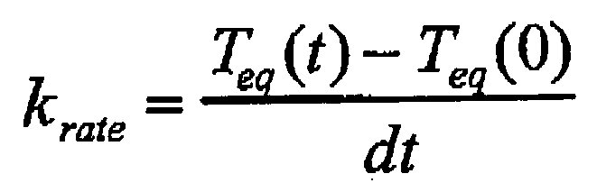
- Similarly, equation (7) leads to the following difference equation:

where
- Equations (6) and (8) can now be transformed into expressions for the component radial growth because of thermal expansion of the component material. The component temperature is replaced directly with thermal growth (dR). The equivalent fluid temperature, on the other hand, represents the driving force of the growth process and is replaced with what is referred to as steady state growth. Steady state growth is the radial growth that the component would have attained had it remained in contact with the fluid indefinitely. Thus, the resulting expressions for thermal growth based on closed form solution to a step input becomes:

- The resulting expression for thermal growth based on closed form solution to a ramp input becomes:

where
- Similarly, equations (2a), (2b) and (2c) are used to obtain the expressions for steady state thermal growth and equivalent time constant:


- In a practical application, such as a clearance model used in a turbine case cooling control system, the thermal growth of the turbomachine component can be accurately represented by equation (9). This is due to a relatively fast model execution rate (e.g. 0.1 sec and less is typically used) on a modern digital computer such as FADEC of gas turbine engine.
- Equation (9) is then fitted with approximating coefficients to arrive at the following version of an on-board transient model of thermal radial growth:

- As can be seen an approximating coefficient "a" appears in (12) as a convenient adjustment factor that allows to adjust steady state growth of the component (e.g. to better fit a particular hardware version of the component). For that and some other reasons additional approximating coefficients are introduced in the expressions for steady state growth and equivalent time constant.
- The approximating equation for steady state growth is derived from equation (11) by introducing two types of approximating coefficients 'k' and 'z' as follows:

- The approximating equation for the equivalent time constant of thermal growth is derived from equation (11) by introducing two types of approximating coefficients 'b' and 'z' as follows:

- The coefficients 'a', k', 'z' and 'b' in the above equations are used to calibrate the component thermal growth model to higher fidelity model and/or test data. This helps to offset a negative effect of the assumptions made when deriving the equations. At the same time it facilitates the model traceability to a specific set of turbomachine hardware which may be changing through the operating life of the machine.
- The obtained model can be utilized to model dynamics of higher order than one. This is accomplished by modeling a turbomachine component as a sum of a finite number of sub-components each represented by the subject model. For example, in the turbine case cooling control system it is often assumed that each of the turbine components (disk, blade and a case) can have up to three sub-components thus raising the order of dynamics to 3. This allows to properly account for complex geometry of the HPT components.
- The following is an example of a set of difference equations and performance parameters that can be used in the control software to model radial thermal growth of a turbomachine component having three subcomponents. The difference equations are given by:

- The performance parameters are given by:




- Note, that except for the case component a single performance parameter is used.
- The steady state thermal growths of disk and blade are correlated as follows:


- Note, the contribution of each of the influence temperatures in equation (17) is apportioned with an approximating coefficient that is constant This differs with the fundamental relationship of equation (11). As was shown, the coefficients vary with the engine operating parameters which is reflected in equation (11). However, it is believed that the resulting errors are small for disk and blade, and equations (17a) and (17b) adequately describe steady state thermal growth of these components.
- The case component on the other hand, experiences a significant change in the influencing coefficients particularly due to changes in turbine case cooling flow. To properly account for that effect the development of steady state growth expression for the case component starts back with physics based relationship (11). It then assumes that in absence of turbine case cooling flow the influence coefficients are constant. The analysis proceeds to establish corrections to these coefficients for the case of non-zero case cooling flow. As described, the additional assumptions made in the development depart from the original result (1). However, it is believed that the main effect of varying case cooling flow is being captured well and preliminary regression analysis gives acceptable results. Omitting detailed derivation steady state growth of case component takes the following form:

where
- In summary, the foregoing analysis shows that an accurate determination of and control of thermal growth of engine components may be accomplished.
Claims (18)
- A method of controlling clearance in a turbomachine (10) between turbomachine component blades (43) and a wall (50) adjacent to and opposing tips (45) of the blades, the method comprising the steps of:determining components (41, 43, 50) and if necessary subcomponents of the turbomachine (10) such that thermal growth of each component or subcomponent is governed by 1st order differential equation in terms of component material temperature;determining fluid streams (48) that exchange heat with the components or subcomponents each characterized by distinct temperature and flow rate;determining from a measurement and/or synthesis the temperatures and flow rates of the fluid streams (48) defined for each of the components (41, 43, 50) or subcomponents;determining from a measurement and/or synthesis parameters appearing in performance parameter correlations including temperatures, pressures and shaft speeds;determining turbomachine component (41, 43, 50) heat transfer performance parameters each as a function of measured and otherwise synthesized engine characteristics including shaft speeds, pressures and temperatures;determining steady state growth of the turbomachine components (41, 43, 50) each as a weighted average of growths resulting from thermal exchange with fluid streams (48) of varying temperatures, flow rates and thermo-physical properties where weighting factors include the heat transfer performance parameters;determining an inverse of an equivalent time constant of the turbomachine components (41, 43, 50) each as a sum of the respective performance parameters;determining thermal growth of the turbomachine components (41, 43, 50) each with a difference equation by applying a closed form solution to a governing first order differential equation over a predetermined time step for a specified change in a forcing function, the forcing function including the steady state growth of the respective turbomachine component, and the time constant including the equivalent time constant;populating the equations for steady state growth, equivalent time constant and thermal growth difference equations with the approximating coefficients that are determined from regression analysis that minimizes errors between the subject thermal growth model and higher fidelity model and/or test data;determining the turbomachine tip clearance as total sum of all the turbomachine component (41, 43, 50) and subcomponent growths where thermal growth of the turbomachine components or subcomponents is obtained with the subject thermal growth model; andcontrolling (40) the turbomachine tip clearance based on the difference between desired and actual clearance of turbomachine components (41, 43, 50) as determined by the thermal growth of the turbomachine components.
- A method of controlling clearance as defined in claim 1, wherein the step of controlling includes adjusting an amount of air flow (33) adjacent to the wall (50) in response to the thermal growth.
- A method of controlling clearance as defined in claim 2, wherein the step of adjusting an amount of air flow (33) includes adjusting a butterfly valve (32).
- A method of controlling clearance as defined in claim 3, wherein the step of adjusting an amount of air flow (33) further includes moving a piston actuator (46) controllably coupled to the butterfly valve (32) by means of a torque motor (44).
- A method of controlling clearance as defined in any preceding claim, wherein the step of determining thermal growth includes determining each heat transfer performance parameter by calculating the result of a first product divided by a second product, the first product including an area of contact of fluid flow (48) and a turbomachine component (41, 43, 50) multiplied by a heat transfer coefficient of fluid flow, and the second product including a specific heat of the turbomachine component multiplied by a mass of the turbomachine component.
- A method of controlling clearance as defined in any preceding claim, wherein the weighted average of thermal growths is based on a plurality of turbomachine (10) sub-components.
- A method of controlling clearance as defined in any preceding claim, wherein the turbomachine (10) is a gas turbine engine, and the wall (50) opposing the tips (45) of the blades (43) is the case of the engine.
- A method of controlling clearance as defined in any preceding claim, wherein the turbomachine (10) is a turbine engine, and the turbomachine components include a blade (43), a disk (41) and a case (50) of the engine.
- A method of controlling clearance as defined in claim 8, wherein sub-components of the disk (41) include a bore, a web and a rim.
- A system for controlling clearance in a turbomachine (10) between turbomachine component blades (43) and a wall (50) adjacent to and opposing tips (45) of the blades, the system comprising:means for determining components (41, 43, 50) and if necessary subcomponents of the turbomachine (10) such that thermal growth of each component or subcomponent is governed by 1st order differential equation in terms of component material temperature;means for determining fluid streams (48) that exchange heat with the components (41, 43, 50) or subcomponents each characterized by distinct temperature and flow rate;means for determining from a measurement and/or synthesis the temperatures and flow rates of the fluid streams (48) defined for each of the components (41, 43, 50) or subcomponents;means for determining from a measurement and/or synthesis parameters appearing in performance parameter correlations including temperatures, pressures and shaft speeds;means for determining turbomachine component heat transfer performance parameters each as a function of measured and otherwise synthesized engine characteristics including shaft speeds, pressures and temperatures;means for determining steady state growth of the turbomachine components (41, 43, 50) each as a weighted average of growths resulting from thermal exchange with fluid streams (48) of varying temperatures, flow rates and thermo-physical properties where weighting factors include the heat transfer performance parameters;means for determining an inverse of an equivalent time constant of the turbomachine components (41, 43, 50) each as a sum of the respective performance parameters;means for determining thermal growth of the turbomachine components each with a difference equation by applying a closed form solution to a governing first order differential equation over a predetermined time step for a specified change in a forcing function, the forcing function including the steady state growth of the respective turbomachine component, and the time constant including the equivalent time constant;means for populating the equations for steady state growth, equivalent time constant and thermal growth difference equations with the approximating coefficients that are determined from regression analysis that minimizes errors between the subject thermal growth model and higher fidelity model and/or test data;means for determining the turbomachine tip clearance as total sum of all the turbomachine component (41, 43, 50) and subcomponent growths where thermal growth of the turbomachine components or subcomponents is obtained with the subject thermal growth model; andmeans for controlling (30) the turbomachine tip clearance based on the difference between desired and actual clearance of turbomachine components (41, 43, 50) as determined by the thermal growth of the turbomachine components.
- A system as defined in claim 10, wherein the controlling means (30) includes means for adjusting (32, 44, 46) an amount of air flow (33) adjacent to the wall (50) in response to the thermal growth.
- A system as defined in claim 10 or 11, wherein the controlling means (30) includes means for determining each heat transfer performance parameter by calculating the result of a first product divided by a second product, the first product including an area of contact of fluid flow (48) and a turbomachine component (41, 43, 50) multiplied by a heat transfer coefficient of fluid flow, and the second product including a specific heat of the turbomachine component multiplied by a mass of the turbomachine component.
- A system as defined in claim 10, 11 or 12, wherein the turbomachine (10) is a gas turbine engine, and the wall (50) opposing the tips (45) of the blades (43) is the case (50) of the engine.
- A turbine engine system (10) comprising:a turbine engine including case (50) and blades (43) rotatable within the case;means for determining components (41, 43, 50) and if necessary subcomponents of the turbine engine such that thermal growth of each component or subcomponent is governed by 1st order differential equation in terms of component material temperature;means for determining fluid streams (48) that exchange heat with the components (41, 43, 50) or subcomponents each characterized by distinct temperature and flow rate;means for determining from a measurement and/or synthesis the temperatures and flow rates of the fluid streams (48) defined for each of the components (41, 43, 50) or subcomponents;means for determining from a measurement and/or synthesis parameters appearing in performance parameter correlations including temperatures, pressures and shaft speeds;means for determining turbine engine component heat transfer performance parameters each as a function of measured and otherwise synthesized engine characteristics including shaft speeds, pressures and temperatures;means for determining steady state growth of the turbine engine components (41, 43, 50) each as a weighted average of growths resulting from thermal exchange with fluid streams (48) of varying temperatures, flow rates and thermo-physical properties where weighting factors include the heat transfer performance parameters;means for determining an inverse of an equivalent time constant of the turbine engine components (41, 43, 50) each as a sum of the respective performance parameters;means for determining thermal growth of the turbine engine components (41, 43, 50) each with a difference equation by applying a closed form solution to a governing first order differential equation over a predetermined time step for a specified change in a forcing function, the forcing function including the steady state growth of the respective turbine engine component, and the time constant including the equivalent time constant;means for populating the equations for steady state growth, equivalent time constant and thermal growth difference equations with the approximating coefficients that are determined from regression analysis that minimizes errors between the subject thermal growth model and higher fidelity model and/or test data;means for determining the turbine engine tip clearance as total sum of all the turbine engine component (41, 43, 50) and subcomponent growths where thermal growth of the turbine engine components or subcomponents is obtained with the subject thermal growth model; andmeans for adjusting (32, 44, 46) an amount of air flow (33) adjacent to the wall (50) in response to the thermal growth.
- A system as defined in claim 14, further including:at least one sensor (38) for measuring engine speed; andat least one sensor (38) for measuring burner pressure, measurements generated by the sensors for determining the temperatures of the turbine engine components (41, 43, 50), the temperature of fluid flow, and the fluid flow rate.
- A system as defined in claim 14 or 15, wherein the adjusting means (32, 44, 46) includes means for determining each heat transfer performance parameter by calculating the result of a first product divided by a second product, the first product including an area of contact of fluid flow (48) and a turbine engine component (41, 43, 50) multiplied by a heat transfer coefficient of fluid flow, and the second product including a specific heat of the turbine engine component multiplied by a mass of the turbine engine component.
- A system as defined in any of claims 10 to 16, wherein the turbine engine or turbomachine (10) is a gas turbine engine.
- A system as defined in any of claims 11 to 17, wherein the controlling means or adjusting means includes:a torque motor (44) communicating with the controlling means;a piston actuator (46) drivingly coupled to the torque motor; anda butterfly valve (32) controllably coupled to the actuator.
Applications Claiming Priority (2)
| Application Number | Priority Date | Filing Date | Title |
|---|---|---|---|
| US09/990,661 US6487491B1 (en) | 2001-11-21 | 2001-11-21 | System and method of controlling clearance between turbine engine blades and case based on engine components thermal growth model |
| US990661 | 2001-11-21 |
Publications (3)
| Publication Number | Publication Date |
|---|---|
| EP1314857A2 EP1314857A2 (en) | 2003-05-28 |
| EP1314857A3 EP1314857A3 (en) | 2005-02-02 |
| EP1314857B1 true EP1314857B1 (en) | 2006-10-25 |
Family
ID=25536392
Family Applications (1)
| Application Number | Title | Priority Date | Filing Date |
|---|---|---|---|
| EP02258021A Expired - Lifetime EP1314857B1 (en) | 2001-11-21 | 2002-11-21 | Controlling turbine blade tip clearance according to thermal growth model |
Country Status (4)
| Country | Link |
|---|---|
| US (1) | US6487491B1 (en) |
| EP (1) | EP1314857B1 (en) |
| JP (1) | JP3720804B2 (en) |
| DE (1) | DE60215602T2 (en) |
Cited By (3)
| Publication number | Priority date | Publication date | Assignee | Title |
|---|---|---|---|---|
| RU2634341C2 (en) * | 2016-03-02 | 2017-10-25 | Акционерное общество "Научно-производственное объединение "Лианозовский электромеханический завод" | Method of testing small-sized blade turbo-machines and test stand for implementation of this method |
| RU2716767C1 (en) * | 2019-09-20 | 2020-03-17 | Федеральное государственное бюджетное учреждение науки Объединенный институт высоких температур Российской академии наук (ОИВТ РАН) | Testing bench of blade compressors and method of gas-dynamic tests of blade compressors |
| RU2779514C1 (en) * | 2021-12-29 | 2022-09-08 | Публичное акционерное общество "Научно-производственное объединение "Алмаз" имени академика А.А. Расплетина" (ПАО "НПО "Алмаз") | Test bench for vane compressors and method for gas-dynamic testing of vane compressors |
Families Citing this family (75)
| Publication number | Priority date | Publication date | Assignee | Title |
|---|---|---|---|---|
| US6853945B2 (en) * | 2003-03-27 | 2005-02-08 | General Electric Company | Method of on-line monitoring of radial clearances in steam turbines |
| US6925814B2 (en) * | 2003-04-30 | 2005-08-09 | Pratt & Whitney Canada Corp. | Hybrid turbine tip clearance control system |
| US20040219011A1 (en) * | 2003-05-02 | 2004-11-04 | General Electric Company | High pressure turbine elastic clearance control system and method |
| US20050109016A1 (en) * | 2003-11-21 | 2005-05-26 | Richard Ullyott | Turbine tip clearance control system |
| US20060013681A1 (en) * | 2004-05-17 | 2006-01-19 | Cardarella L J Jr | Turbine case reinforcement in a gas turbine jet engine |
| FR2871513B1 (en) * | 2004-06-15 | 2006-09-22 | Snecma Moteurs Sa | SYSTEM AND METHOD FOR CONTROLLING AN AIR FLOW IN A GAS TURBINE |
| US8191254B2 (en) | 2004-09-23 | 2012-06-05 | Carlton Forge Works | Method and apparatus for improving fan case containment and heat resistance in a gas turbine jet engine |
| US7455495B2 (en) * | 2005-08-16 | 2008-11-25 | United Technologies Corporation | Systems and methods for monitoring thermal growth and controlling clearances, and maintaining health of turbo machinery applications |
| US8065022B2 (en) * | 2005-09-06 | 2011-11-22 | General Electric Company | Methods and systems for neural network modeling of turbine components |
| FR2890685B1 (en) * | 2005-09-14 | 2007-12-14 | Snecma | TURBINE HIGH ROTOR ROTOR AUTONOMOUS ROTOR CONTROL IN A TURBOMACHINE |
| US7491029B2 (en) | 2005-10-14 | 2009-02-17 | United Technologies Corporation | Active clearance control system for gas turbine engines |
| GB0609312D0 (en) * | 2006-05-11 | 2006-06-21 | Rolls Royce Plc | Clearance Control Apparatus |
| DE102006033461A1 (en) * | 2006-07-19 | 2008-01-31 | Siemens Ag | Radial gap measurement on turbines |
| US7368827B2 (en) * | 2006-09-06 | 2008-05-06 | Siemens Power Generation, Inc. | Electrical assembly for monitoring conditions in a combustion turbine operating environment |
| US8801370B2 (en) * | 2006-10-12 | 2014-08-12 | General Electric Company | Turbine case impingement cooling for heavy duty gas turbines |
| US7837429B2 (en) * | 2006-10-12 | 2010-11-23 | General Electric Company | Predictive model based control system for heavy duty gas turbines |
| US7823389B2 (en) * | 2006-11-15 | 2010-11-02 | General Electric Company | Compound clearance control engine |
| JP2008180220A (en) * | 2007-01-24 | 2008-08-07 | General Electric Co <Ge> | Predictive model control system for high horsepower gas turbines. |
| US7891938B2 (en) * | 2007-03-20 | 2011-02-22 | General Electric Company | Multi sensor clearance probe |
| US7927067B2 (en) * | 2007-05-01 | 2011-04-19 | United Technologies Corporation | System and method for controlling stator assemblies |
| DE102007035927A1 (en) * | 2007-07-31 | 2009-02-05 | Mtu Aero Engines Gmbh | Control for a gas turbine with actively stabilized compressor |
| US8126628B2 (en) * | 2007-08-03 | 2012-02-28 | General Electric Company | Aircraft gas turbine engine blade tip clearance control |
| US8616827B2 (en) | 2008-02-20 | 2013-12-31 | Rolls-Royce Corporation | Turbine blade tip clearance system |
| JP2009243444A (en) * | 2008-03-31 | 2009-10-22 | Ihi Corp | Jet engine |
| US8256228B2 (en) * | 2008-04-29 | 2012-09-04 | Rolls Royce Corporation | Turbine blade tip clearance apparatus and method |
| US8192152B2 (en) * | 2008-05-02 | 2012-06-05 | United Technologies Corporation | Repaired internal holding structures for gas turbine engine cases and method of repairing the same |
| US8257039B2 (en) * | 2008-05-02 | 2012-09-04 | United Technologies Corporation | Gas turbine engine case with replaced flange and method of repairing the same using cold metal transfer |
| US8510926B2 (en) * | 2008-05-05 | 2013-08-20 | United Technologies Corporation | Method for repairing a gas turbine engine component |
| DE102009024870A1 (en) | 2008-06-10 | 2009-12-31 | Carl Zeiss Smt Ag | Optical device with adjustable force acting on an optical module |
| US8321104B2 (en) | 2008-07-18 | 2012-11-27 | Rolls-Royce Plc | Control system |
| US8090456B2 (en) * | 2008-11-03 | 2012-01-03 | United Technologies Corporation | System and method for design and control of engineering systems utilizing component-level dynamic mathematical model |
| DE102009010647A1 (en) * | 2009-02-26 | 2010-09-02 | Rolls-Royce Deutschland Ltd & Co Kg | Running column adjustment system of an aircraft gas turbine |
| US8315741B2 (en) * | 2009-09-02 | 2012-11-20 | United Technologies Corporation | High fidelity integrated heat transfer and clearance in component-level dynamic turbine system control |
| US8668434B2 (en) * | 2009-09-02 | 2014-03-11 | United Technologies Corporation | Robust flow parameter model for component-level dynamic turbine system control |
| JP5439597B2 (en) * | 2010-06-28 | 2014-03-12 | 株式会社日立製作所 | Gas turbine gap diagnostic device and gas turbine system |
| WO2012001726A1 (en) * | 2010-06-28 | 2012-01-05 | 株式会社 日立製作所 | Gas turbine gap assessment device and gas turbine system |
| FR2971543B1 (en) * | 2011-02-11 | 2013-03-08 | Snecma | METHOD FOR CONTROLLING TURBINE ROTOR BLACK SUMP |
| US8727312B2 (en) | 2011-04-21 | 2014-05-20 | Hamilton Sundstrand Corporation | Butterfly valve |
| US8682563B2 (en) | 2011-08-30 | 2014-03-25 | General Electric Company | System and method for predicting turbine rub |
| GB201121426D0 (en) | 2011-12-14 | 2012-01-25 | Rolls Royce Plc | Controller |
| WO2013102098A1 (en) | 2011-12-29 | 2013-07-04 | Rolls-Royce North American Technologies, Inc. | Vavle for gas turbine engine |
| US9447696B2 (en) | 2012-12-27 | 2016-09-20 | United Technologies Corporation | Blade outer air seal system for controlled tip clearance |
| EP2954173A1 (en) | 2013-02-08 | 2015-12-16 | General Electric Company | Suction-based active clearance control system |
| EP2959117B1 (en) | 2013-02-23 | 2019-07-03 | Rolls-Royce North American Technologies, Inc. | Blade clearance control for gas turbine engine |
| EP2972604B1 (en) | 2013-03-15 | 2020-04-29 | United Technologies Corporation | Compact aero-thermo model based control system estimator starting algorithm |
| GB201307646D0 (en) * | 2013-04-29 | 2013-06-12 | Rolls Royce Plc | Rotor tip clearance |
| JP6090926B2 (en) * | 2013-05-30 | 2017-03-08 | 三菱重工業株式会社 | Turbo compressor and turbo refrigerator using the same |
| GB2516048A (en) * | 2013-07-09 | 2015-01-14 | Rolls Royce Plc | Tip clearance control method |
| GB201315365D0 (en) | 2013-08-29 | 2013-10-09 | Rolls Royce Plc | Rotor tip clearance |
| RU2554544C2 (en) * | 2013-09-26 | 2015-06-27 | Федеральное государственное унитарное предприятие "Центральный институт авиационного моторостроения имени П.И. Баранова" | Digital electronic control system with built-in complete thermo- and gas-dynamic mathematical model of gas turbine engine, and aircraft gas turbine engine |
| US10329940B2 (en) * | 2013-10-04 | 2019-06-25 | General Electric Company | Method and system for passive clearance control in a gas turbine engine |
| US9266618B2 (en) | 2013-11-18 | 2016-02-23 | Honeywell International Inc. | Gas turbine engine turbine blade tip active clearance control system and method |
| WO2015153171A1 (en) * | 2014-03-31 | 2015-10-08 | United Technologies Corporation | Active clearance control for gas turbine engine |
| US9810091B2 (en) | 2014-08-12 | 2017-11-07 | United Technologies Corporation | Smart active clearance control between a rotor blade and a shroud |
| DE102015206088A1 (en) * | 2015-04-02 | 2016-10-06 | Rolls-Royce Deutschland Ltd & Co Kg | Aircraft gas turbine engine with annular gap closure element |
| DE102015206091A1 (en) * | 2015-04-02 | 2016-10-06 | Rolls-Royce Deutschland Ltd & Co Kg | Aircraft gas turbine engine with annular gap closure element |
| US10711702B2 (en) | 2015-08-18 | 2020-07-14 | General Electric Company | Mixed flow turbocore |
| US10578028B2 (en) | 2015-08-18 | 2020-03-03 | General Electric Company | Compressor bleed auxiliary turbine |
| GB201518641D0 (en) * | 2015-10-21 | 2015-12-02 | Rolls Royce Plc | A system and method |
| US20170191420A1 (en) * | 2015-12-31 | 2017-07-06 | General Electric Company | Method and system for equipment compartment cooling |
| CA2959708C (en) | 2016-03-11 | 2019-04-16 | General Electric Company | Method and apparatus for active clearance control |
| US9777633B1 (en) * | 2016-03-30 | 2017-10-03 | General Electric Company | Secondary airflow passage for adjusting airflow distortion in gas turbine engine |
| US10329941B2 (en) | 2016-05-06 | 2019-06-25 | United Technologies Corporation | Impingement manifold |
| US10822991B2 (en) | 2016-08-01 | 2020-11-03 | General Electric Company | Method and apparatus for active clearance control on gas turbine engines |
| US20180073440A1 (en) * | 2016-09-13 | 2018-03-15 | General Electric Company | Controlling turbine shroud clearance for operation protection |
| FR3059042B1 (en) * | 2016-11-22 | 2020-07-17 | Safran Aircraft Engines | METHOD FOR CONTROLLING A TURBOMACHINE VALVE |
| US9939247B1 (en) | 2016-12-05 | 2018-04-10 | United Technologies Corporation | Embedded sensor for in-situ monitoring of blade tip incursion |
| US10428676B2 (en) * | 2017-06-13 | 2019-10-01 | Rolls-Royce Corporation | Tip clearance control with variable speed blower |
| US11193387B2 (en) | 2017-07-11 | 2021-12-07 | General Electric Company | Performance and life optimizing control system for a turbine engine |
| CN110318823B (en) * | 2019-07-10 | 2022-07-15 | 中国航发沈阳发动机研究所 | Active clearance control method and device |
| US11939070B2 (en) | 2020-02-21 | 2024-03-26 | General Electric Company | Engine-mounting links that have an adjustable inclination angle |
| US11970279B2 (en) | 2020-02-21 | 2024-04-30 | General Electric Company | Control system and methods of controlling an engine-mounting link system |
| US11713689B2 (en) * | 2021-01-18 | 2023-08-01 | General Electric Company | Clearance design process and strategy with CCA-ACC optimization for EGT and performance improvement |
| US20240200465A1 (en) * | 2022-12-20 | 2024-06-20 | General Electric Company | Methods and apparatus to target engine operating cycle conditions for clearance control |
| US12104492B1 (en) * | 2023-09-25 | 2024-10-01 | Rolls-Royce North American Technologies Inc. | Turbine assembly with clearance sensor having integrated internal cooling |
Family Cites Families (4)
| Publication number | Priority date | Publication date | Assignee | Title |
|---|---|---|---|---|
| US4329114A (en) * | 1979-07-25 | 1982-05-11 | The United States Of America As Represented By The Administrator Of The National Aeronautics And Space Administration | Active clearance control system for a turbomachine |
| US5012420A (en) | 1988-03-31 | 1991-04-30 | General Electric Company | Active clearance control for gas turbine engine |
| US5545007A (en) * | 1994-11-25 | 1996-08-13 | United Technologies Corp. | Engine blade clearance control system with piezoelectric actuator |
| US6272422B2 (en) * | 1998-12-23 | 2001-08-07 | United Technologies Corporation | Method and apparatus for use in control of clearances in a gas turbine engine |
-
2001
- 2001-11-21 US US09/990,661 patent/US6487491B1/en not_active Expired - Lifetime
-
2002
- 2002-11-21 DE DE60215602T patent/DE60215602T2/en not_active Expired - Lifetime
- 2002-11-21 JP JP2002337345A patent/JP3720804B2/en not_active Expired - Fee Related
- 2002-11-21 EP EP02258021A patent/EP1314857B1/en not_active Expired - Lifetime
Cited By (4)
| Publication number | Priority date | Publication date | Assignee | Title |
|---|---|---|---|---|
| RU2634341C2 (en) * | 2016-03-02 | 2017-10-25 | Акционерное общество "Научно-производственное объединение "Лианозовский электромеханический завод" | Method of testing small-sized blade turbo-machines and test stand for implementation of this method |
| RU2716767C1 (en) * | 2019-09-20 | 2020-03-17 | Федеральное государственное бюджетное учреждение науки Объединенный институт высоких температур Российской академии наук (ОИВТ РАН) | Testing bench of blade compressors and method of gas-dynamic tests of blade compressors |
| RU2779514C1 (en) * | 2021-12-29 | 2022-09-08 | Публичное акционерное общество "Научно-производственное объединение "Алмаз" имени академика А.А. Расплетина" (ПАО "НПО "Алмаз") | Test bench for vane compressors and method for gas-dynamic testing of vane compressors |
| RU2789295C1 (en) * | 2022-06-03 | 2023-02-01 | Федеральное Автономное Учреждение "Центральный институт авиационного моторостроения имени П.И. Баранова" | Device for gas-dynamic testing of bladed machines of a gas turbine plant |
Also Published As
| Publication number | Publication date |
|---|---|
| DE60215602T2 (en) | 2007-08-23 |
| JP3720804B2 (en) | 2005-11-30 |
| EP1314857A2 (en) | 2003-05-28 |
| EP1314857A3 (en) | 2005-02-02 |
| US6487491B1 (en) | 2002-11-26 |
| DE60215602D1 (en) | 2006-12-07 |
| JP2003214114A (en) | 2003-07-30 |
Similar Documents
| Publication | Publication Date | Title |
|---|---|---|
| US6487491B1 (en) | System and method of controlling clearance between turbine engine blades and case based on engine components thermal growth model | |
| EP2149824B1 (en) | Methods and systems for estimating operating parameters of an engine | |
| EP1298512B1 (en) | Adaptive aero-thermodynamic engine model | |
| EP1985862B1 (en) | Controlling operation of a compressor to avoid compressor instability | |
| US5012420A (en) | Active clearance control for gas turbine engine | |
| US8849542B2 (en) | Real time linearization of a component-level gas turbine engine model for model-based control | |
| EP1013891B1 (en) | Method and apparatus for use in control and compensation of clearances in a gas turbine engine | |
| US11242766B2 (en) | Method and device for measuring the flow rate of cooling air in a turbomachine casing | |
| CN110647052B (en) | An adaptive ID card model construction method for variable cycle engine mode switching | |
| RU2736403C1 (en) | Turbojet engine control method | |
| EP4177473B1 (en) | Method of controlling the geometrical configuration of a variable geometry element in a gas turbine engine compressor stage | |
| Dunn et al. | Heat-flux and pressure measurements and comparison with prediction for a low-aspect-ratio turbine stage | |
| Grunwitz et al. | A comprehensive multifidelity design and analysis process for cooled axial flow turbines: From concept to component | |
| EP4119775B1 (en) | Active clearance control system and method for an aircraft engine | |
| Berdanier | An experimental characterization of tip leakage flows and corresponding effects on multistage compressor performance | |
| Tian et al. | Profile predictive body force model for axial compressor based on prior loss and deviation estimation | |
| Perez et al. | Detailed Experimental Measurement and RANS Simulation of a Low Pressure Turbine With High Lift Blading | |
| Bergholz et al. | Rotor/stator heat transfer measurements and CFD predictions for short-duration turbine rig tests | |
| Ebus et al. | Detailed Performance Studies on a Small Electric-Powered Contra-Rotating Ducted Fan Engine | |
| Budo et al. | Assessment of geometric variability effects through a viscous through-flow model applied to modern axial-flow compressor blades | |
| Metzger et al. | Turbine tip and shroud heat transfer | |
| Sokolov et al. | Advances in High-Speed Linear Design Technology: Novel Approach to Sidewall Geometry Design for Erosion Tests | |
| Zawadzki et al. | GReTa-An Open-Source Generic Research Turbofan Low-Pressure Compressor Model | |
| Hudson et al. | Performance testing of a highly loaded single stage oxidizer turbine with inlet and exit volute manifolds | |
| Herrera et al. | A comparative analysis of turbine rotor inlet temperature models |
Legal Events
| Date | Code | Title | Description |
|---|---|---|---|
| PUAI | Public reference made under article 153(3) epc to a published international application that has entered the european phase |
Free format text: ORIGINAL CODE: 0009012 |
|
| AK | Designated contracting states |
Designated state(s): AT BE BG CH CY CZ DE DK EE ES FI FR GB GR IE IT LI LU MC NL PT SE SK TR |
|
| AX | Request for extension of the european patent |
Extension state: AL LT LV MK RO SI |
|
| PUAL | Search report despatched |
Free format text: ORIGINAL CODE: 0009013 |
|
| AK | Designated contracting states |
Kind code of ref document: A3 Designated state(s): AT BE BG CH CY CZ DE DK EE ES FI FR GB GR IE IT LI LU MC NL PT SE SK TR |
|
| AX | Request for extension of the european patent |
Extension state: AL LT LV MK RO SI |
|
| 17P | Request for examination filed |
Effective date: 20050629 |
|
| AKX | Designation fees paid |
Designated state(s): DE FR GB |
|
| GRAP | Despatch of communication of intention to grant a patent |
Free format text: ORIGINAL CODE: EPIDOSNIGR1 |
|
| GRAS | Grant fee paid |
Free format text: ORIGINAL CODE: EPIDOSNIGR3 |
|
| GRAA | (expected) grant |
Free format text: ORIGINAL CODE: 0009210 |
|
| AK | Designated contracting states |
Kind code of ref document: B1 Designated state(s): DE FR GB |
|
| REG | Reference to a national code |
Ref country code: GB Ref legal event code: FG4D |
|
| REF | Corresponds to: |
Ref document number: 60215602 Country of ref document: DE Date of ref document: 20061207 Kind code of ref document: P |
|
| ET | Fr: translation filed | ||
| PLBE | No opposition filed within time limit |
Free format text: ORIGINAL CODE: 0009261 |
|
| STAA | Information on the status of an ep patent application or granted ep patent |
Free format text: STATUS: NO OPPOSITION FILED WITHIN TIME LIMIT |
|
| 26N | No opposition filed |
Effective date: 20070726 |
|
| PGFP | Annual fee paid to national office [announced via postgrant information from national office to epo] |
Ref country code: FR Payment date: 20081106 Year of fee payment: 7 |
|
| REG | Reference to a national code |
Ref country code: FR Ref legal event code: ST Effective date: 20100730 |
|
| PG25 | Lapsed in a contracting state [announced via postgrant information from national office to epo] |
Ref country code: FR Free format text: LAPSE BECAUSE OF NON-PAYMENT OF DUE FEES Effective date: 20091130 |
|
| REG | Reference to a national code |
Ref country code: DE Ref legal event code: R082 Ref document number: 60215602 Country of ref document: DE Representative=s name: SCHMITT-NILSON SCHRAUD WAIBEL WOHLFROM PATENTA, DE |
|
| REG | Reference to a national code |
Ref country code: DE Ref legal event code: R082 Ref document number: 60215602 Country of ref document: DE Representative=s name: SCHMITT-NILSON SCHRAUD WAIBEL WOHLFROM PATENTA, DE Ref country code: DE Ref legal event code: R081 Ref document number: 60215602 Country of ref document: DE Owner name: UNITED TECHNOLOGIES CORP. (N.D.GES.D. STAATES , US Free format text: FORMER OWNER: UNITED TECHNOLOGIES CORP., HARTFORD, CONN., US |
|
| PGFP | Annual fee paid to national office [announced via postgrant information from national office to epo] |
Ref country code: DE Payment date: 20191021 Year of fee payment: 18 |
|
| PGFP | Annual fee paid to national office [announced via postgrant information from national office to epo] |
Ref country code: GB Payment date: 20191022 Year of fee payment: 18 |
|
| REG | Reference to a national code |
Ref country code: DE Ref legal event code: R119 Ref document number: 60215602 Country of ref document: DE |
|
| GBPC | Gb: european patent ceased through non-payment of renewal fee |
Effective date: 20201121 |
|
| PG25 | Lapsed in a contracting state [announced via postgrant information from national office to epo] |
Ref country code: DE Free format text: LAPSE BECAUSE OF NON-PAYMENT OF DUE FEES Effective date: 20210601 Ref country code: GB Free format text: LAPSE BECAUSE OF NON-PAYMENT OF DUE FEES Effective date: 20201121 |