EP1314629A2 - Feel control for active steering - Google Patents
Feel control for active steering Download PDFInfo
- Publication number
- EP1314629A2 EP1314629A2 EP02079498A EP02079498A EP1314629A2 EP 1314629 A2 EP1314629 A2 EP 1314629A2 EP 02079498 A EP02079498 A EP 02079498A EP 02079498 A EP02079498 A EP 02079498A EP 1314629 A2 EP1314629 A2 EP 1314629A2
- Authority
- EP
- European Patent Office
- Prior art keywords
- input
- low
- signal
- controller
- motor
- Prior art date
- Legal status (The legal status is an assumption and is not a legal conclusion. Google has not performed a legal analysis and makes no representation as to the accuracy of the status listed.)
- Withdrawn
Links
- 238000000034 method Methods 0.000 claims abstract description 12
- 238000001914 filtration Methods 0.000 claims abstract description 7
- 238000004891 communication Methods 0.000 claims description 10
- 238000012886 linear function Methods 0.000 claims 1
- 230000006870 function Effects 0.000 description 42
- 230000004044 response Effects 0.000 description 6
- 238000013461 design Methods 0.000 description 4
- 238000012360 testing method Methods 0.000 description 4
- 238000012546 transfer Methods 0.000 description 3
- 230000001052 transient effect Effects 0.000 description 3
- 238000010586 diagram Methods 0.000 description 2
- 230000009471 action Effects 0.000 description 1
- 230000000712 assembly Effects 0.000 description 1
- 238000000429 assembly Methods 0.000 description 1
- 230000003416 augmentation Effects 0.000 description 1
- 230000008859 change Effects 0.000 description 1
- 230000000052 comparative effect Effects 0.000 description 1
- 230000000694 effects Effects 0.000 description 1
- 238000013507 mapping Methods 0.000 description 1
- 230000007246 mechanism Effects 0.000 description 1
- 238000012986 modification Methods 0.000 description 1
- 230000004048 modification Effects 0.000 description 1
- 238000012545 processing Methods 0.000 description 1
- 230000009467 reduction Effects 0.000 description 1
- 230000035807 sensation Effects 0.000 description 1
- 230000001131 transforming effect Effects 0.000 description 1
Images


Classifications
-
- B—PERFORMING OPERATIONS; TRANSPORTING
- B62—LAND VEHICLES FOR TRAVELLING OTHERWISE THAN ON RAILS
- B62D—MOTOR VEHICLES; TRAILERS
- B62D6/00—Arrangements for automatically controlling steering depending on driving conditions sensed and responded to, e.g. control circuits
- B62D6/008—Control of feed-back to the steering input member, e.g. simulating road feel in steer-by-wire applications
-
- B—PERFORMING OPERATIONS; TRANSPORTING
- B62—LAND VEHICLES FOR TRAVELLING OTHERWISE THAN ON RAILS
- B62D—MOTOR VEHICLES; TRAILERS
- B62D5/00—Power-assisted or power-driven steering
- B62D5/008—Changing the transfer ratio between the steering wheel and the steering gear by variable supply of energy, e.g. by using a superposition gear
Definitions
- Conventional vehicular steering systems have an articulated mechanical linkage connecting an input device (e.g., steering wheel or hand-wheel) to a steering actuator (e.g., steerable road wheel).
- a steering wheel motion directly corresponds to a resulting motion of the steerable road wheels with a fixed mapping.
- a given motion of the steering wheel may be supplemented by the motion of a differential actuator, for example, to produce a motion of the steerable road wheels that need not correspond to the given motion of the steering wheel.
- the differential actuator is inactive, the motion of the steerable road wheels directly corresponds to the steering wheel motion due to the articulated mechanical linkage, as in conventional systems.
- An operator of such an active steering vehicle can generally feel the forces acting against the steering actuator through the input device, as well as reaction forces typically induced by the actively controlled differential actuator.
- a method and apparatus for controlling the feel back torque of a motor provides for receiving a difference between a desired motor position and an actual motor position; filtering the difference into two or more frequency bands; and applying a variable gain to one or more of the filtered frequency bands in correspondence with the received signal or a low-pass portion of the received signal to provide a motor command.
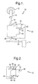
- an active steering system for a vehicle is indicated generally by the reference numeral 10.
- the active steering system 10 includes an input device, specifically a hand-wheel 12 in this embodiment, in operable communication with a steering actuator, specifically a pair of road wheels 14 (only one shown) in this embodiment.
- the exemplary active steering system 10 may be referred to as a front-controlled steering (“FCS”) system when employed to steer the front wheels of a road vehicle, as is currently preferred.
- FCS front-controlled steering
- the hand-wheel 12 is connected to a steering hub 16, which is connected, in turn, to a first end of a steering input shaft 18.
- a hand-wheel position sensor 20 is disposed at the steering input shaft 18 for sensing the position of the hand-wheel 12.
- the steering input shaft 18 is connected at its second end to a differential actuator 22.
- a differential actuator 22 may also be used.
- the differential actuator 22 includes an actuator housing 24, which receives the steering input shaft 18 as its first input, and provides a steering output shaft 26.
- a motor 30 is connected to a motor shaft 32, which is received by the actuator housing 24 as its second input.
- a steering rack 34 is connected to the steering output shaft 26.
- a road-wheel position sensor 28 is disposed at the steering output shaft 26 for sensing the position of the road-wheels 14.
- a controller 35 is in signal communication between the hand-wheel position sensor 20, the road-wheel position sensor 28, and the motor 30.
- the differential actuator 22 of FIG. 1 preferably includes a first gear 36 affixed to a lower end of the steering input shaft 18, and meshingly engaged with a second gear 38.
- the second gear 38 is affixed, in turn, to a differential input shaft 40, which enters an upper wall of a differential unit 42.
- a differential output shaft 44 projects from a lower wall of the differential unit 42, and is connected at its lower end to a third gear 46.
- the third gear 46 is meshingly engaged with a fourth gear 48, which is meshingly engaged with a fifth gear 50.
- the motor shaft 32 which is connected to the motor 30, enters through a sidewall of the differential unit 42.
- the differential unit 42 of FIG. 2 comprises a differential housing 51. Within the housing 51, a lower end of the differential input shaft 40 is axially connected to an input gear 52. The input gear 52 is meshingly engaged with a first spur gear 54 and a second spur gear 56. The spur gears 54 and 56 are meshingly engaged with an output gear 58, which is connected to an upper end of the differential output shaft 44.
- the motor shaft 32 which is connected to the motor 30, enters through a sidewall of the differential housing 51, and includes a worm drive 60 at its inner end.
- the worm drive 60 is meshingly engaged with a worm gear 62, which rotatably receives the differential input shaft 40 through its axial center.
- the differential input shaft 40 is free to rotate within the worm gear 62.
- the worm gear 62 fixedly supports a cage 63, which, in turn, fixedly supports a spindle 64, which spindle rotatably receives the spur gears 54 and 56 through their axial centers, respectively.
- a parallel-axis differential assembly having a differential carrier that comprises an input sun gear meshed with input differential planet gears, input differential planet gears meshed with output differential planet gears, and an output sun gear meshed with the output differential planet gears.
- a feel control algorithm for use in an active steering system is indicated generally by the reference numeral 66.
- the feel control algorithm 66 receives a signal indicative of commanded motor position on input line 68, which is passed to a non-inverting input of a summing function 70.
- a signal indicative of actual motor position is received on input line 72, which is passed to an inverting input of the summing function 70.
- the output of the summing function 70 is an error signal 73 that is passed to a low-pass filter 74, as well as to a non-inverting input of a summing function 76.
- the output of the low-pass filter 74 is passed to an inverting input of the summing function 76, as well as to a low-pass gain function 78.
- the output of summing function 76 is passed to a high-pass gain function 80, which passes its output to a non-inverting input of a summing function 82.
- the output of the low-pass gain function 78 is received at a second non-inverting input of the summing function 82.
- the output of the summing function 82 is passed to output line 84, and represents a signal indicative of a motor command to be applied to the motor 30 of FIGS. 1 through 3.
- the feel control algorithm 166 receives a signal indicative of commanded motor position at input terminal 168, which is passed to a non-inverting input of a summing function 170.
- the commanded motor position at input terminal 168 may be a function of variable steering ratio considerations, vehicle stability considerations, or a combination thereof.
- a signal indicative of actual motor position is received at input terminal 172, which is passed to an inverting input of the summing function 170.
- the output of the summing function 170 is an error signal 171 that is passed to a low-pass filter 174, as well as to a non-inverting input of a summing function 176, and to an absolute value function 173.
- the output of the absolute value function 173 is passed to a first input of a low-pass gain look-up table 177, as well as to a first input of a high-pass gain look-up table 179.
- the output of the low-pass filter 174 is passed to an inverting input of the summing function 176, as well as to an absolute value function 175, and to a first input of a multiplication function 178.
- the output of the summing function 176 is passed to a first input of a multiplication function 180.
- the output of the absolute value function 175 is passed to a second input of the low-pass gain look-up table 177, as well as to a second input of the high-pass gain look-up table 179.
- the output of the low-pass gain look-up table 177 is passed to a second input of the multiplication function 178, while the output of the high-pass gain look-up table 179 is passed to a second input of the multiplication function 180.
- the output of the multiplication function 180 is passed to a first non-inverting input of a summing function 182.
- the output of the multiplication function 178 is received at a second non-inverting input of the summing function 182.
- the output of the summing function 182 is passed to a control gain function 181, the output of which is then passed, in turn, to a saturation function 183.
- the output of the saturation function 183 is passed to output terminal 184, and represents a signal indicative of a motor command to be applied to the motor 30 of FIGs. 1 through 3.
- the steering position of the front road wheels is determined by the motor 30 in addition to the inputs received at the hand-wheel 12. That is, the position of the steerable road wheels is simply a scaled summation of the hand-wheel position (driver intent) and the motor position (actuation contribution).
- the motor position itself can be derived from various sources, including but not limited to such sources as vehicle and steering signals, in order to meet design criteria.
- a reaction torque is generated by the differential actuator 22 and is felt by the driver through the hand-wheel 12.
- the feel control algorithms of FIGs. 4 and 5 reduce the objectionable components of the feel back torque by responding differently to different input signal frequency components.
- the feel control algorithms of FIGs. 4 and 5 do not eliminate the feel back torque to the driver, but control it by transforming the frequency, duration, amplitude and/or transient characteristics of the feel back torque.
- the feel control algorithms 66 of FIG. 4 and 166 of FIG. 5 may be employed as an integral part of an active steering or front controlled steering (FCS) system.
- the feel control algorithm 66 begins by taking the difference or error between the commanded and actual motor position signals at summing function 70. Without a feel control algorithm, this error would have typically been scaled up or down to form a final motor command. The higher the scaling, the sooner the motor servos the error and achieves its commanded position. With the driver holding rigidly, however, this higher scaling would have caused the transient "feel back" sensations felt by the driver to have increased.
- the comparable error signal is divided into two paths: a high frequency path, and a low frequency path.
- Each path is scaled with a corresponding gain K l and K h , respectively, either of which may be constant in some embodiments.
- the two paths are then summed to form a modified motor command signal, which then moves the motor 30 accordingly.
- this exemplary embodiment uses two paths, any multiple of paths may be used in alternate embodiments wherein each path may include a different filter.
- a pure low-pass filter would slow down the response of the FCS system by filtering out high frequencies in the error signal.
- a pure high-pass filter would speed up the response, but would be unresponsive to a steady error signal.
- the feel control algorithm is structured such that it responds differently to different kinds of input error transients. Testing indicates that drivers tolerate high-frequency transients differently than low-frequency transients.
- a low-pass frequency response plot of a FCS system 10 is indicated generally by the reference numeral 200.
- the complex vehicle dynamics were simplified to a compliance. Accordingly, the steering rack 34 of FIG. 1 was attached to linear springs, rather than road wheels, that were designed to represent vehicle loads at various conditions (e.g., highway). The steering wheel was held rigidly at center. Accordingly, the frequency response plot 200 shows the highest possible feel back torques to the driver.
- the plot 200 includes a magnitude plot 202, and a phase plot 204. The plotted output represents the hand-wheel torque.
- a high-pass frequency response plot of a FCS system 10 is indicated generally by the reference numeral 300.
- the complex vehicle dynamics were simplified to a compliance. Accordingly, the steering rack 34 of FIG. 1 was attached to linear springs, rather than road wheels, that were designed to represent vehicle loads for various conditions (e.g., highway). The steering wheel was held rigidly at center.
- a first order filter is shown in this exemplary embodiment, higher order filters may be used in alternate embodiments in order to meet design criteria.
- FIGs. 6 and 7 indicate that a balance is preferably struck between stability, feel back control, and achieving design criteria related to the vehicle-level benefits of an FCS system. As the high-pass action is added, the system becomes more stable, but the driver will feel more of the high frequency inputs, as shown in FIG. 7. A balance is struck by scheduling the gains K l and K h . Testing indicates that a driver is more tolerant of a larger pulse-like feel-back torque if its duration is short.
- the preferred embodiment of FIG. 5 is provided to allow for both K l and K h gains to be adjusted as a function of the magnitude of the error signal.
- K h the gain goes down as the magnitude of the error signal is increased in order to shield the driver from harsh or high-magnitude feel back torques.
- the same or comparable method may be used for K l .
- the tables and gains for the feel control algorithm 166 of FIG. 5 are preferably tuned in accordance with in-vehicle testing of f c , and the K l and K h tables.
- non-linear tables for K l and K h are indexed on both (or alternatively, either) the error signal and/or the low-pass portion of the error signal.
- Absolute value functions 173 and 175 are used for processing efficiency.
- the saturation function 183 is used to limit the final output command or control signal.
- the low-pass filter 174 may take any of a variety of forms, and is not limited to a first-order filter in alternate embodiments. These tables may also be indexed by other parameters, such as, for examples, vehicle state estimates, environment estimates, and driver preferences.
- FIG. 8 shows a time-wise plot of hand-wheel torque, indicated generally by the reference numeral 400.
- the plot 400 shows a signal trace 402 of the hand-wheel torque using a conventional proportional-only control, and a signal trace 404 of the hand-wheel torque using the feel control algorithm described above with respect to FIG. 5. These plots are the result of running tests for a single lane change on a packed-snow surface at roughly 40 MPH. The plots show the reduction in the high-frequency component of torque variations for the feel control algorithm.
- the peak-valley-peak as shown in the circled region 406 is greatly reduced using a feel control algorithm as described above.
- This peak-valley-peak transient is objectionable due to its low-frequency content.
- the absolute magnitude of the peak produced by the feel control algorithm may be higher than for proportional controllers, it is much less objectionable to a driver due to its short duration and high frequency.
- control algorithms may include, but are not limited to, input devices such as pedals and actuators such as linear motors, and more generally, any controlled device in contact with human skin. It is understood that such control algorithms are applicable to lane keeping systems and steer by wire systems, in addition to hand-wheel actuation in a front controlled steering application. Therefore, it is intended that the Claims not be limited to the particular embodiments disclosed as the currently preferred best modes contemplated for carrying out the teachings herein, but that the Claims shall cover all embodiments falling within the true scope and spirit of the disclosure.
Landscapes
- Engineering & Computer Science (AREA)
- Chemical & Material Sciences (AREA)
- Combustion & Propulsion (AREA)
- Transportation (AREA)
- Mechanical Engineering (AREA)
- Steering Control In Accordance With Driving Conditions (AREA)
- Power Steering Mechanism (AREA)
Abstract
Description
Claims (27)
- A method for controlling a feel back torque of a motor (30), the method comprising:receiving a signal (73) indicative of a difference between a desired motor position (68) and an actual motor position (72);filtering the received signal (73) into a plurality of frequency bands; andapplying a gain to at least one of the filtered frequency bands in correspondence with at least one of the received signal and a low-pass portion of the received signal to provide a motor command (84).
- A method as defined in Claim 1 wherein the motor (30) is disposed relative to a differential (24).
- A method as defined in Claim 2 wherein the motor (30) and differential (24) are comprised by an active steering system (10).
- A method as defined in Claim 1 wherein said gain is variable.
- A method as defined in Claim 1 wherein said gain is scheduled.
- A controller (35) for an active steering system (10), the controller (35) comprising:wherein at least one of a high-pass gain and a low-pass gain correspond to at least one of an error signal (171) and the low-pass portion of the error signal (171).a feel control algorithm (166) for controlling a feel back torque to a driver;
- A controller (35) as defined in Claim 6 wherein the at least one of a high-pass gain and a low-pass gain comprise a scheduling table (177), (179) indexed on the at least one of an error signal (171) and the low-pass portion of the error signal (171).
- A controller (35) as defined in Claim 7 wherein said scheduling table is further indexed on at least one of a vehicle state estimate, an environment estimate, and a driver preference.
- A controller (35) as defined in Claim 6 wherein at least one of the high-pass gain and the low-pass gain is a non-linear function of the at least one of an error signal (171) and the low-pass portion of the error signal (171).
- A controller (35) as defined in Claim 6 further comprising at least one absolute value function (173), (175) in signal communication with the at least one of a high-pass gain and a low-pass gain.
- A controller (35) as defined in Claim 6 further comprising a final output saturation check function (183) in signal communication with the at least one of a high-pass gain and a low-pass gain.
- A controller (35) as defined in Claim 6 wherein the low-pass filter (74), (174) is a first-order filter.
- A controller (35) for an active steering system (10), the controller (35) comprising:means for receiving a signal (73) indicative of a difference between a desired motor position (68) and an actual motor position (72);means for filtering the received signal (73) into a plurality of frequency bands; andmeans for applying a gain to at least one of the filtered frequency bands in correspondence with at least one of the received signal and a low-pass portion of the received signal to provide a motor command (84).
- A method for actively controlling the steering of a motor vehicle, the method comprising:receiving an operator input from an operator of the motor vehicle;receiving a stability input indicative of the dynamic stability of the motor vehicle;calculating a correction signal in accordance with the operator input and the stability input;filtering the correction signal into a plurality of frequency bands;applying a gain to at least one of the filtered bands to produce an output signal corresponding to a desired feel back torque; andadjusting an input to a differential actuator (22) in accordance with the output signal.
- A method as defined in Claim 14 wherein said adjusting comprises:providing the output signal to an electric motor (30) disposed relative to the differential actuator (22) in order to adjust a steering angle of a steering actuator while maintaining desirable feel back torque characteristics.
- An active steering system (10) comprising:an input device;a differential actuator (24) in operable communication with said input device (12);a steering actuator (14) in operable communication with said differential actuator (22); anda feel controller in signal communication with said input device (12), said steering actuator (14), and said differential actuator (22) for controlling a feel back torque to an operator.
- An active steering system (10) as defined in Claim 16, the differential actuator (22) comprising:a motor (30) in signal communication with said feel controller; anda differential unit (42) disposed relative to said motor (30), said input device (12), and said steering actuator (14).
- An active steering system (10) as defined in Claim 17 wherein said differential unit (42) is configured to provide a steering angle to said steering actuator (14) that is substantially independent of an input from an operator.
- An active steering system (10) as defined in Claim 17 wherein said differential unit (42) further comprises:an input gear (52) axially affixed to a differential input shaft (40);an output gear (58) axially affixed to a differential output shaft (44);a first spur gear (54) meshingly engaged with said input gear (52) and said output gear (58);a second spur gear (56) meshingly engaged with said input gear (52) and said output gear (58); anda worm drive (60) meshingly engaged with a worm gear (62), said worm gear (62) rotatingly receiving said differential input shaft (40) therethrough.
- An active steering system (10) as defined in Claim 19 wherein said worm drive (60) is disposed at an end of a motor shaft (32), said motor shaft (32) being coupled to said motor (30).
- An active steering system (10) as defined in Claim 16 wherein said feel controller comprises a high-pass gain function (80) and a low-pass gain function (78).
- An active steering system (10) as defined in Claim 16 wherein said feel controller comprises a low-pass filter (74), (174)for dividing a signal into a low-frequency component and a high-frequency component.
- An active steering system (10) as defined in Claim 22 wherein said feel controller further comprises a summing function (70), (76), (82), (170), (176), (182) for receiving the input of the low-pass filter (74), (174) and the output of the low-pass filter (74), (174), and for providing an input to a high-pass gain function (80).
- An active steering system (10) as defined in Claim 16 further comprising an assist controller in signal communication with said steering actuator (14).
- An active steering system (10) as defined in Claim 24 wherein said feel controller is in signal communication with said assist controller for adjusting a variable assist.
- An active steering system (10) comprising:means for receiving a steering input from an operator of the motor vehicle;means for receiving a stability input indicative of the dynamic stability of the motor vehicle;means for calculating a correction signal in accordance with the steering input and the stability input;means for filtering the correction signal into a plurality of frequency bands;means for applying a gain to at least one of the filtered bands to produce an output signal corresponding to a desired feel back torque; andmeans for adjusting an input to a differential actuator (22) in accordance with the output signal.
- A motor controller (35), comprising:wherein at least one of a high-pass gain and a low-pass gain correspond to at least one of an error signal (171) and a low-pass portion of the error signal (171).a feel control algorithm (66), (166) for controlling a feel back torque to an operator;
Applications Claiming Priority (2)
| Application Number | Priority Date | Filing Date | Title |
|---|---|---|---|
| US990741 | 2001-11-21 | ||
| US09/990,741 US6942057B2 (en) | 2001-11-21 | 2001-11-21 | Feel control for active steering |
Publications (2)
| Publication Number | Publication Date |
|---|---|
| EP1314629A2 true EP1314629A2 (en) | 2003-05-28 |
| EP1314629A3 EP1314629A3 (en) | 2005-02-09 |
Family
ID=25536492
Family Applications (1)
| Application Number | Title | Priority Date | Filing Date |
|---|---|---|---|
| EP02079498A Withdrawn EP1314629A3 (en) | 2001-11-21 | 2002-10-28 | Feel control for active steering |
Country Status (2)
| Country | Link |
|---|---|
| US (1) | US6942057B2 (en) |
| EP (1) | EP1314629A3 (en) |
Families Citing this family (55)
| Publication number | Priority date | Publication date | Assignee | Title |
|---|---|---|---|---|
| US7219761B2 (en) * | 2000-07-21 | 2007-05-22 | Nsk Ltd. | Motor-operated power steering apparatus |
| AU2003262082A1 (en) * | 2002-09-19 | 2004-04-08 | Nsk Ltd. | Control device for motorized power steering device |
| JP4089435B2 (en) * | 2003-01-08 | 2008-05-28 | 株式会社ジェイテクト | Electric power steering device |
| US7063636B2 (en) * | 2003-06-16 | 2006-06-20 | Delphi Technologies, Inc. | Mechanically linked active steering system |
| JP4293106B2 (en) * | 2004-10-14 | 2009-07-08 | トヨタ自動車株式会社 | Control device for electric power steering device |
| JP4760626B2 (en) * | 2006-09-06 | 2011-08-31 | トヨタ自動車株式会社 | Torque control device for power system |
| US7933701B2 (en) * | 2006-12-28 | 2011-04-26 | Caterpillar Inc. | Closed-loop motion-control system using error to modify gain |
| US7881841B2 (en) * | 2006-12-28 | 2011-02-01 | Caterpillar Inc. | Motion-control system |
| JP5499526B2 (en) * | 2009-06-19 | 2014-05-21 | 株式会社ジェイテクト | Electric power steering device |
| WO2013018420A1 (en) * | 2011-08-04 | 2013-02-07 | 本田技研工業株式会社 | Electric power steering device |
| EP2907730B1 (en) | 2014-01-29 | 2017-09-06 | Steering Solutions IP Holding Corporation | Hands on steering wheel detect |
| JP6446832B2 (en) * | 2014-05-16 | 2019-01-09 | 株式会社ジェイテクト | Steering device |
| US20160137225A1 (en) * | 2014-11-19 | 2016-05-19 | Steering Solutions Ip Holding Corporation | Handwheel position detection system |
| US10351159B2 (en) | 2015-05-01 | 2019-07-16 | Steering Solutions Ip Holding Corporation | Retractable steering column with a radially projecting attachment |
| US10589774B2 (en) | 2015-05-01 | 2020-03-17 | Steering Solutions Ip Holding Corporation | Counter rotation steering wheel |
| US9919724B2 (en) | 2015-05-29 | 2018-03-20 | Steering Solutions Ip Holding Corporation | Retractable steering column with manual retrieval |
| US10343706B2 (en) | 2015-06-11 | 2019-07-09 | Steering Solutions Ip Holding Corporation | Retractable steering column system, vehicle having the same, and method |
| US11560169B2 (en) * | 2015-06-11 | 2023-01-24 | Steering Solutions Ip Holding Corporation | Retractable steering column system and method |
| DE102016110791A1 (en) | 2015-06-15 | 2016-12-15 | Steering Solutions Ip Holding Corporation | Gesture control for a retractable steering wheel |
| US10577009B2 (en) | 2015-06-16 | 2020-03-03 | Steering Solutions Ip Holding Corporation | Retractable steering column assembly and method |
| US9828016B2 (en) | 2015-06-24 | 2017-11-28 | Steering Solutions Ip Holding Corporation | Retractable steering column system, vehicle having the same, and method |
| DE102016111473A1 (en) | 2015-06-25 | 2016-12-29 | Steering Solutions Ip Holding Corporation | STATIONARY STEERING WHEEL ASSEMBLY AND METHOD |
| US20160375931A1 (en) | 2015-06-25 | 2016-12-29 | Steering Solutions Ip Holding Corporation | Rotation control system for a steering wheel and method |
| US10112639B2 (en) | 2015-06-26 | 2018-10-30 | Steering Solutions Ip Holding Corporation | Vehicle steering arrangement and method of making same |
| US9840271B2 (en) | 2015-06-29 | 2017-12-12 | Steering Solutions Ip Holding Corporation | Retractable steering column with rake limiter |
| US9849904B2 (en) | 2015-07-31 | 2017-12-26 | Steering Solutions Ip Holding Corporation | Retractable steering column with dual actuators |
| US9845106B2 (en) | 2015-08-31 | 2017-12-19 | Steering Solutions Ip Holding Corporation | Overload protection for belt drive mechanism |
| US10160472B2 (en) | 2015-10-20 | 2018-12-25 | Steering Solutions Ip Holding Corporation | Steering column with stationary hub |
| US9809155B2 (en) | 2015-10-27 | 2017-11-07 | Steering Solutions Ip Holding Corporation | Retractable steering column assembly having lever, vehicle having retractable steering column assembly, and method |
| US10029725B2 (en) | 2015-12-03 | 2018-07-24 | Steering Solutions Ip Holding Corporation | Torque feedback system for a steer-by-wire vehicle, vehicle having steering column, and method of providing feedback in vehicle |
| JP6876242B2 (en) * | 2015-12-24 | 2021-05-26 | 株式会社ジェイテクト | Handle operation status judgment device |
| US10496102B2 (en) | 2016-04-11 | 2019-12-03 | Steering Solutions Ip Holding Corporation | Steering system for autonomous vehicle |
| DE102017108692B4 (en) | 2016-04-25 | 2024-09-26 | Steering Solutions Ip Holding Corporation | Control of an electric power steering system using system state predictions |
| US10351161B2 (en) | 2016-05-27 | 2019-07-16 | Steering Solutions Ip Holding Corporation | Steering column with manual retraction |
| US10421476B2 (en) | 2016-06-21 | 2019-09-24 | Steering Solutions Ip Holding Corporation | Self-locking telescope actuator of a steering column assembly |
| US10457313B2 (en) | 2016-06-28 | 2019-10-29 | Steering Solutions Ip Holding Corporation | ADAS wheel locking device |
| US10363958B2 (en) | 2016-07-26 | 2019-07-30 | Steering Solutions Ip Holding Corporation | Electric power steering mode determination and transitioning |
| US10160477B2 (en) | 2016-08-01 | 2018-12-25 | Steering Solutions Ip Holding Corporation | Electric power steering column assembly |
| US10189496B2 (en) | 2016-08-22 | 2019-01-29 | Steering Solutions Ip Holding Corporation | Steering assembly having a telescope drive lock assembly |
| US10384708B2 (en) | 2016-09-12 | 2019-08-20 | Steering Solutions Ip Holding Corporation | Intermediate shaft assembly for steer-by-wire steering system |
| US10160473B2 (en) | 2016-09-13 | 2018-12-25 | Steering Solutions Ip Holding Corporation | Steering column decoupling system |
| US10399591B2 (en) | 2016-10-03 | 2019-09-03 | Steering Solutions Ip Holding Corporation | Steering compensation with grip sensing |
| US10239552B2 (en) | 2016-10-14 | 2019-03-26 | Steering Solutions Ip Holding Corporation | Rotation control assembly for a steering column |
| US10481602B2 (en) | 2016-10-17 | 2019-11-19 | Steering Solutions Ip Holding Corporation | Sensor fusion for autonomous driving transition control |
| US10421475B2 (en) | 2016-11-15 | 2019-09-24 | Steering Solutions Ip Holding Corporation | Electric actuator mechanism for retractable steering column assembly with manual override |
| US10310605B2 (en) | 2016-11-15 | 2019-06-04 | Steering Solutions Ip Holding Corporation | Haptic feedback for steering system controls |
| US9862403B1 (en) | 2016-11-29 | 2018-01-09 | Steering Solutions Ip Holding Corporation | Manually retractable steering column assembly for autonomous vehicle |
| US10351160B2 (en) | 2016-11-30 | 2019-07-16 | Steering Solutions Ip Holding Corporation | Steering column assembly having a sensor assembly |
| US10780915B2 (en) | 2016-12-07 | 2020-09-22 | Steering Solutions Ip Holding Corporation | Vehicle steering system having a user experience based automated driving to manual driving transition system and method |
| US10370022B2 (en) | 2017-02-13 | 2019-08-06 | Steering Solutions Ip Holding Corporation | Steering column assembly for autonomous vehicle |
| US10385930B2 (en) | 2017-02-21 | 2019-08-20 | Steering Solutions Ip Holding Corporation | Ball coupling assembly for steering column assembly |
| US10449927B2 (en) | 2017-04-13 | 2019-10-22 | Steering Solutions Ip Holding Corporation | Steering system having anti-theft capabilities |
| US10556614B2 (en) | 2017-07-11 | 2020-02-11 | Nio Usa, Inc. | Body mounted sliding steering column with offset feedback actuator |
| US10457314B2 (en) * | 2017-06-26 | 2019-10-29 | Nio Usa, Inc. | Retractable telescopic mechanism for steering column with feedback actuator |
| US10875566B2 (en) | 2018-03-22 | 2020-12-29 | Steering Solutions Ip Holding Corporation | Stow release assembly for a manually adjustable steering column assembly |
Family Cites Families (47)
| Publication number | Priority date | Publication date | Assignee | Title |
|---|---|---|---|---|
| US3765624A (en) * | 1971-09-29 | 1973-10-16 | Us Navy | Fluidically augmented variable gain artificial feel system |
| US4078749A (en) * | 1977-05-24 | 1978-03-14 | United Technologies Corporation | Helicopter stick force augmentation null offset compensation |
| US4576056A (en) * | 1982-07-16 | 1986-03-18 | Automobiles Citroen | Rotary assistance mechanism, particularly for vehicle steering |
| JPS60193765A (en) | 1984-03-16 | 1985-10-02 | Hitachi Ltd | power steering control device |
| US4676331A (en) * | 1984-12-20 | 1987-06-30 | Kabushiki Kaisha Toyoda Jidoshokki Seisakusho | Torque detecting apparatus for electrical power steering system |
| JPS62214055A (en) * | 1986-03-13 | 1987-09-19 | Aisin Seiki Co Ltd | Electric power steering device |
| JPH0643187B2 (en) | 1986-04-22 | 1994-06-08 | 株式会社日立製作所 | Electric power steering device |
| US4715462A (en) * | 1986-05-29 | 1987-12-29 | Allied Corporation | Electric power assistance steering system |
| JPS638071A (en) * | 1986-06-25 | 1988-01-13 | Hitachi Ltd | Electric power steering device |
| JP2682564B2 (en) * | 1987-07-01 | 1997-11-26 | 本田技研工業株式会社 | Electric power steering device |
| US4951199A (en) | 1987-11-16 | 1990-08-21 | Whitehead John C | Steering stabilizing method and apparatus for suppressing the weave mode |
| ES2061071T3 (en) * | 1989-11-03 | 1994-12-01 | Bishop A E | STEERING SYSTEM TO THE FOUR WHEELS. |
| DE4031316C2 (en) | 1990-10-04 | 2001-11-22 | Bosch Gmbh Robert | Motorized power steering system |
| JP2580865B2 (en) | 1990-10-17 | 1997-02-12 | 三菱自動車工業株式会社 | Vehicle steering control device |
| US5347204A (en) * | 1992-10-06 | 1994-09-13 | Honeywell Inc. | Position dependent rate dampening in any active hand controller |
| DE4304664C2 (en) * | 1993-02-16 | 2000-04-06 | Daimler Chrysler Ag | Control device, in particular steering for motor vehicles |
| JPH06351270A (en) * | 1993-06-04 | 1994-12-22 | Canon Inc | Controller for ultrasonic motor |
| US5473231A (en) * | 1994-05-11 | 1995-12-05 | Trw Inc. | Method and apparatus for controlling an electric assist steering system using an adaptive torque filter |
| JP3493806B2 (en) | 1995-04-21 | 2004-02-03 | 日本精工株式会社 | Control device for electric power steering device |
| US5722620A (en) * | 1995-05-15 | 1998-03-03 | The Boeing Company | Aircraft pitch-axis stability and command augmentation |
| MY120887A (en) * | 1995-06-08 | 2005-12-30 | Sony Corp | Rotation position detecting device and motor device. |
| US5719766A (en) | 1995-10-02 | 1998-02-17 | General Motors Corporation | Electric power steering control |
| US5704446A (en) * | 1995-10-02 | 1998-01-06 | General Motors Corporation | Electric power steering control |
| JPH09269804A (en) * | 1996-03-29 | 1997-10-14 | Aisin Seiki Co Ltd | Stable controller for automatic control system |
| JP3109023B2 (en) * | 1996-07-18 | 2000-11-13 | セイコー精機株式会社 | Magnetic bearing device |
| US6085860A (en) | 1997-03-22 | 2000-07-11 | Robert Bosch Gmbh | Method and apparatus for operating a steering system for a motor vehicle |
| US6226579B1 (en) | 1997-03-22 | 2001-05-01 | Robert Bosch Gmbh | Method and apparatus for operating a steering system for a motor vehicle |
| DE19713245C2 (en) * | 1997-03-29 | 2001-02-15 | Mercedes Benz Lenkungen Gmbh | Motor vehicle with at least one part controllable via at least one control lever in the form of a so-called side stick |
| JP3128531B2 (en) * | 1997-04-03 | 2001-01-29 | 本田技研工業株式会社 | Electric power steering device |
| US6039143A (en) * | 1997-06-02 | 2000-03-21 | General Motors Corporation | Steerable drive axle with electrically-powered steering apparatus |
| EP0900710B1 (en) * | 1997-09-05 | 2002-06-19 | Mitsubishi Denki Kabushiki Kaisha | Electric power steering controller |
| US6107767A (en) * | 1998-03-20 | 2000-08-22 | Trw Inc. | Electric assist steering system having an improved motor current controller with notch filter |
| US6370459B1 (en) * | 1998-07-21 | 2002-04-09 | Techco Corporation | Feedback and servo control for electric power steering systems |
| JP3298006B2 (en) * | 1998-12-24 | 2002-07-02 | 日本精工株式会社 | Control device for electric power steering device |
| US6176341B1 (en) * | 1999-02-01 | 2001-01-23 | Delphi Technologies, Inc. | Vehicle steering system having master/slave configuration and method therefor |
| US6122579A (en) * | 1999-05-28 | 2000-09-19 | Delphi Technologies, Inc. | Electric power steering control with torque ripple and road disturbance damper |
| JP3353770B2 (en) * | 1999-08-19 | 2002-12-03 | 三菱電機株式会社 | Electric power steering controller |
| JP3791253B2 (en) * | 1999-08-30 | 2006-06-28 | スズキ株式会社 | Torque detection device |
| US6363305B1 (en) * | 1999-09-17 | 2002-03-26 | Delphi Technologies, Inc. | Steer-by-wire system |
| DE60043861D1 (en) * | 1999-12-29 | 2010-04-01 | Delphi Tech Inc | METHOD AND SYSTEM FOR IMPROVING MOTOR VEHICLE STABILITY USING AN ELECTRIC POWER STEERING SYSTEM |
| JP4128719B2 (en) * | 2000-02-25 | 2008-07-30 | 三菱電機株式会社 | Electric power steering control device and control method thereof |
| JP3663330B2 (en) | 2000-02-29 | 2005-06-22 | 光洋精工株式会社 | Electric power steering device |
| US6575265B2 (en) * | 2000-03-30 | 2003-06-10 | Delphi Technologies, Inc. | Linear differential assisted controlled steering |
| US6422335B1 (en) * | 2000-04-11 | 2002-07-23 | Trw Inc. | Method and apparatus for controlling steering feel with diagnostics |
| US6625530B1 (en) * | 2000-11-06 | 2003-09-23 | Delphi Technologies, Inc. | Feed forward—feed back control for steer-by-wire system |
| US6453226B1 (en) | 2001-01-25 | 2002-09-17 | Delphi Technologies, Inc. | Integrated control of active tire steer and brakes |
| US6591937B2 (en) | 2001-12-05 | 2003-07-15 | Delphi Technologies, Inc. | Adaptive variable effort power steering system |
-
2001
- 2001-11-21 US US09/990,741 patent/US6942057B2/en not_active Expired - Fee Related
-
2002
- 2002-10-28 EP EP02079498A patent/EP1314629A3/en not_active Withdrawn
Also Published As
| Publication number | Publication date |
|---|---|
| US6942057B2 (en) | 2005-09-13 |
| US20030094330A1 (en) | 2003-05-22 |
| EP1314629A3 (en) | 2005-02-09 |
Similar Documents
| Publication | Publication Date | Title |
|---|---|---|
| US6942057B2 (en) | Feel control for active steering | |
| US5704446A (en) | Electric power steering control | |
| EP3041752B1 (en) | Steering apparatus and steering controller | |
| US5668722A (en) | Electric power steering control | |
| US6789641B2 (en) | Method and apparatus for controlling an electric assist motor using a modified blending filter | |
| US5719766A (en) | Electric power steering control | |
| US8996251B2 (en) | Electric power-steering control device | |
| JP4286834B2 (en) | Steering control device | |
| EP2221235B1 (en) | Electric power steering apparatus, control method thereof and program | |
| EP1228941A2 (en) | A user-configurable steering control for steer-by-wire systems | |
| EP1203710A2 (en) | Feed forward-feed back control for steer-by-wire system | |
| US20100198461A1 (en) | Method and apparatus for controlling an electric assist motor using a modified blending filter | |
| WO2006099483A1 (en) | Method and apparatus for controlling an electric assist steering system using an adaptive blending torque filter and road feel filter | |
| US8296011B2 (en) | Systems and methods involving quadrant dependent active damping | |
| CN118082968B (en) | Information fusion-based steering road feel simulation calculation method and device and vehicle | |
| EP1884447A1 (en) | Quadrant dependant active damping for electric power steering | |
| CN102105340A (en) | Vehicle steering apparatus | |
| EP2402234B1 (en) | Dynamic system compensator for actively controlled power steering systems | |
| US7931113B2 (en) | Steering control system for vehicle | |
| CN112061229A (en) | Friction compensation method of electric power steering system | |
| EP0842841B1 (en) | Electric power steering control | |
| US6600280B2 (en) | Electric power steering system | |
| CN116605286A (en) | Transmission ratio calculation method, application and system for steer-by-wire system | |
| EP0842840A1 (en) | Electric power steering control | |
| JP2006273185A (en) | Vehicle steering system |
Legal Events
| Date | Code | Title | Description |
|---|---|---|---|
| PUAI | Public reference made under article 153(3) epc to a published international application that has entered the european phase |
Free format text: ORIGINAL CODE: 0009012 |
|
| AK | Designated contracting states |
Designated state(s): AT BE BG CH CY CZ DE DK EE ES FI FR GB GR IE IT LI LU MC NL PT SE SK TR |
|
| AX | Request for extension of the european patent |
Extension state: AL LT LV MK RO SI |
|
| PUAL | Search report despatched |
Free format text: ORIGINAL CODE: 0009013 |
|
| AK | Designated contracting states |
Kind code of ref document: A3 Designated state(s): AT BE BG CH CY CZ DE DK EE ES FI FR GB GR IE IT LI LU MC NL PT SE SK TR |
|
| AX | Request for extension of the european patent |
Extension state: AL LT LV MK RO SI |
|
| STAA | Information on the status of an ep patent application or granted ep patent |
Free format text: STATUS: THE APPLICATION IS DEEMED TO BE WITHDRAWN |
|
| AKX | Designation fees paid | ||
| 18D | Application deemed to be withdrawn |
Effective date: 20050503 |
|
| REG | Reference to a national code |
Ref country code: DE Ref legal event code: 8566 |