EP1314535A1 - Method and apparatus for blowmolding, in particular inside cooling during in-mold handle attachment - Google Patents
Method and apparatus for blowmolding, in particular inside cooling during in-mold handle attachment Download PDFInfo
- Publication number
- EP1314535A1 EP1314535A1 EP02026174A EP02026174A EP1314535A1 EP 1314535 A1 EP1314535 A1 EP 1314535A1 EP 02026174 A EP02026174 A EP 02026174A EP 02026174 A EP02026174 A EP 02026174A EP 1314535 A1 EP1314535 A1 EP 1314535A1
- Authority
- EP
- European Patent Office
- Prior art keywords
- blow
- container
- cooling medium
- handle
- exhaust
- Prior art date
- Legal status (The legal status is an assumption and is not a legal conclusion. Google has not performed a legal analysis and makes no representation as to the accuracy of the status listed.)
- Withdrawn
Links
Images


Classifications
-
- B—PERFORMING OPERATIONS; TRANSPORTING
- B29—WORKING OF PLASTICS; WORKING OF SUBSTANCES IN A PLASTIC STATE IN GENERAL
- B29C—SHAPING OR JOINING OF PLASTICS; SHAPING OF MATERIAL IN A PLASTIC STATE, NOT OTHERWISE PROVIDED FOR; AFTER-TREATMENT OF THE SHAPED PRODUCTS, e.g. REPAIRING
- B29C49/00—Blow-moulding, i.e. blowing a preform or parison to a desired shape within a mould; Apparatus therefor
- B29C49/42—Component parts, details or accessories; Auxiliary operations
- B29C49/78—Measuring, controlling or regulating
- B29C49/783—Measuring, controlling or regulating blowing pressure
-
- B—PERFORMING OPERATIONS; TRANSPORTING
- B29—WORKING OF PLASTICS; WORKING OF SUBSTANCES IN A PLASTIC STATE IN GENERAL
- B29C—SHAPING OR JOINING OF PLASTICS; SHAPING OF MATERIAL IN A PLASTIC STATE, NOT OTHERWISE PROVIDED FOR; AFTER-TREATMENT OF THE SHAPED PRODUCTS, e.g. REPAIRING
- B29C49/00—Blow-moulding, i.e. blowing a preform or parison to a desired shape within a mould; Apparatus therefor
- B29C49/20—Blow-moulding, i.e. blowing a preform or parison to a desired shape within a mould; Apparatus therefor of articles having inserts or reinforcements ; Handling of inserts or reinforcements
-
- B—PERFORMING OPERATIONS; TRANSPORTING
- B29—WORKING OF PLASTICS; WORKING OF SUBSTANCES IN A PLASTIC STATE IN GENERAL
- B29C—SHAPING OR JOINING OF PLASTICS; SHAPING OF MATERIAL IN A PLASTIC STATE, NOT OTHERWISE PROVIDED FOR; AFTER-TREATMENT OF THE SHAPED PRODUCTS, e.g. REPAIRING
- B29C49/00—Blow-moulding, i.e. blowing a preform or parison to a desired shape within a mould; Apparatus therefor
- B29C49/42—Component parts, details or accessories; Auxiliary operations
- B29C49/64—Heating or cooling preforms, parisons or blown articles
- B29C49/66—Cooling by refrigerant introduced into the blown article
-
- B—PERFORMING OPERATIONS; TRANSPORTING
- B29—WORKING OF PLASTICS; WORKING OF SUBSTANCES IN A PLASTIC STATE IN GENERAL
- B29C—SHAPING OR JOINING OF PLASTICS; SHAPING OF MATERIAL IN A PLASTIC STATE, NOT OTHERWISE PROVIDED FOR; AFTER-TREATMENT OF THE SHAPED PRODUCTS, e.g. REPAIRING
- B29C49/00—Blow-moulding, i.e. blowing a preform or parison to a desired shape within a mould; Apparatus therefor
- B29C49/20—Blow-moulding, i.e. blowing a preform or parison to a desired shape within a mould; Apparatus therefor of articles having inserts or reinforcements ; Handling of inserts or reinforcements
- B29C2049/2017—Blow-moulding, i.e. blowing a preform or parison to a desired shape within a mould; Apparatus therefor of articles having inserts or reinforcements ; Handling of inserts or reinforcements outside the article
-
- B—PERFORMING OPERATIONS; TRANSPORTING
- B29—WORKING OF PLASTICS; WORKING OF SUBSTANCES IN A PLASTIC STATE IN GENERAL
- B29C—SHAPING OR JOINING OF PLASTICS; SHAPING OF MATERIAL IN A PLASTIC STATE, NOT OTHERWISE PROVIDED FOR; AFTER-TREATMENT OF THE SHAPED PRODUCTS, e.g. REPAIRING
- B29C49/00—Blow-moulding, i.e. blowing a preform or parison to a desired shape within a mould; Apparatus therefor
- B29C49/20—Blow-moulding, i.e. blowing a preform or parison to a desired shape within a mould; Apparatus therefor of articles having inserts or reinforcements ; Handling of inserts or reinforcements
- B29C2049/2021—Inserts characterised by the material or type
- B29C2049/2034—Attachments, e.g. hooks to hold or hang the blown article
- B29C2049/2039—Handles, e.g. handles or grips on bottles
-
- B—PERFORMING OPERATIONS; TRANSPORTING
- B29—WORKING OF PLASTICS; WORKING OF SUBSTANCES IN A PLASTIC STATE IN GENERAL
- B29C—SHAPING OR JOINING OF PLASTICS; SHAPING OF MATERIAL IN A PLASTIC STATE, NOT OTHERWISE PROVIDED FOR; AFTER-TREATMENT OF THE SHAPED PRODUCTS, e.g. REPAIRING
- B29C49/00—Blow-moulding, i.e. blowing a preform or parison to a desired shape within a mould; Apparatus therefor
- B29C49/42—Component parts, details or accessories; Auxiliary operations
- B29C49/48—Moulds
- B29C49/4823—Moulds with incorporated heating or cooling means
- B29C2049/4838—Moulds with incorporated heating or cooling means for heating moulds or mould parts
- B29C2049/4846—Moulds with incorporated heating or cooling means for heating moulds or mould parts in different areas of the mould at different temperatures, e.g. neck, shoulder or bottom
-
- B—PERFORMING OPERATIONS; TRANSPORTING
- B29—WORKING OF PLASTICS; WORKING OF SUBSTANCES IN A PLASTIC STATE IN GENERAL
- B29C—SHAPING OR JOINING OF PLASTICS; SHAPING OF MATERIAL IN A PLASTIC STATE, NOT OTHERWISE PROVIDED FOR; AFTER-TREATMENT OF THE SHAPED PRODUCTS, e.g. REPAIRING
- B29C49/00—Blow-moulding, i.e. blowing a preform or parison to a desired shape within a mould; Apparatus therefor
- B29C49/42—Component parts, details or accessories; Auxiliary operations
- B29C49/58—Blowing means
- B29C2049/5837—Plural independent blowing means
-
- B—PERFORMING OPERATIONS; TRANSPORTING
- B29—WORKING OF PLASTICS; WORKING OF SUBSTANCES IN A PLASTIC STATE IN GENERAL
- B29C—SHAPING OR JOINING OF PLASTICS; SHAPING OF MATERIAL IN A PLASTIC STATE, NOT OTHERWISE PROVIDED FOR; AFTER-TREATMENT OF THE SHAPED PRODUCTS, e.g. REPAIRING
- B29C49/00—Blow-moulding, i.e. blowing a preform or parison to a desired shape within a mould; Apparatus therefor
- B29C49/42—Component parts, details or accessories; Auxiliary operations
- B29C49/64—Heating or cooling preforms, parisons or blown articles
- B29C49/6604—Thermal conditioning of the blown article
- B29C2049/6606—Cooling the article
- B29C2049/6607—Flushing blown articles
- B29C2049/6615—Flushing blown articles and exhausting through the blowing means
-
- B—PERFORMING OPERATIONS; TRANSPORTING
- B29—WORKING OF PLASTICS; WORKING OF SUBSTANCES IN A PLASTIC STATE IN GENERAL
- B29C—SHAPING OR JOINING OF PLASTICS; SHAPING OF MATERIAL IN A PLASTIC STATE, NOT OTHERWISE PROVIDED FOR; AFTER-TREATMENT OF THE SHAPED PRODUCTS, e.g. REPAIRING
- B29C49/00—Blow-moulding, i.e. blowing a preform or parison to a desired shape within a mould; Apparatus therefor
- B29C49/42—Component parts, details or accessories; Auxiliary operations
- B29C49/64—Heating or cooling preforms, parisons or blown articles
- B29C49/6604—Thermal conditioning of the blown article
- B29C2049/6606—Cooling the article
- B29C2049/6607—Flushing blown articles
- B29C2049/6623—Flushing blown articles and exhausting through an opening in the blown article
-
- B—PERFORMING OPERATIONS; TRANSPORTING
- B29—WORKING OF PLASTICS; WORKING OF SUBSTANCES IN A PLASTIC STATE IN GENERAL
- B29C—SHAPING OR JOINING OF PLASTICS; SHAPING OF MATERIAL IN A PLASTIC STATE, NOT OTHERWISE PROVIDED FOR; AFTER-TREATMENT OF THE SHAPED PRODUCTS, e.g. REPAIRING
- B29C49/00—Blow-moulding, i.e. blowing a preform or parison to a desired shape within a mould; Apparatus therefor
- B29C49/42—Component parts, details or accessories; Auxiliary operations
- B29C49/64—Heating or cooling preforms, parisons or blown articles
- B29C49/6604—Thermal conditioning of the blown article
- B29C2049/6606—Cooling the article
- B29C2049/6676—Cooling the article the medium being oriented towards special areas of the blown article
-
- B—PERFORMING OPERATIONS; TRANSPORTING
- B29—WORKING OF PLASTICS; WORKING OF SUBSTANCES IN A PLASTIC STATE IN GENERAL
- B29C—SHAPING OR JOINING OF PLASTICS; SHAPING OF MATERIAL IN A PLASTIC STATE, NOT OTHERWISE PROVIDED FOR; AFTER-TREATMENT OF THE SHAPED PRODUCTS, e.g. REPAIRING
- B29C49/00—Blow-moulding, i.e. blowing a preform or parison to a desired shape within a mould; Apparatus therefor
- B29C49/42—Component parts, details or accessories; Auxiliary operations
- B29C49/78—Measuring, controlling or regulating
- B29C49/783—Measuring, controlling or regulating blowing pressure
- B29C2049/7831—Measuring, controlling or regulating blowing pressure characterised by pressure values or ranges
-
- B—PERFORMING OPERATIONS; TRANSPORTING
- B29—WORKING OF PLASTICS; WORKING OF SUBSTANCES IN A PLASTIC STATE IN GENERAL
- B29C—SHAPING OR JOINING OF PLASTICS; SHAPING OF MATERIAL IN A PLASTIC STATE, NOT OTHERWISE PROVIDED FOR; AFTER-TREATMENT OF THE SHAPED PRODUCTS, e.g. REPAIRING
- B29C49/00—Blow-moulding, i.e. blowing a preform or parison to a desired shape within a mould; Apparatus therefor
- B29C49/42—Component parts, details or accessories; Auxiliary operations
- B29C49/78—Measuring, controlling or regulating
- B29C49/783—Measuring, controlling or regulating blowing pressure
- B29C2049/7832—Blowing with two or more pressure levels
- B29C2049/7833—Blowing with three or more pressure levels
-
- B—PERFORMING OPERATIONS; TRANSPORTING
- B29—WORKING OF PLASTICS; WORKING OF SUBSTANCES IN A PLASTIC STATE IN GENERAL
- B29C—SHAPING OR JOINING OF PLASTICS; SHAPING OF MATERIAL IN A PLASTIC STATE, NOT OTHERWISE PROVIDED FOR; AFTER-TREATMENT OF THE SHAPED PRODUCTS, e.g. REPAIRING
- B29C2949/00—Indexing scheme relating to blow-moulding
- B29C2949/07—Preforms or parisons characterised by their configuration
- B29C2949/0715—Preforms or parisons characterised by their configuration the preform having one end closed
-
- B—PERFORMING OPERATIONS; TRANSPORTING
- B29—WORKING OF PLASTICS; WORKING OF SUBSTANCES IN A PLASTIC STATE IN GENERAL
- B29C—SHAPING OR JOINING OF PLASTICS; SHAPING OF MATERIAL IN A PLASTIC STATE, NOT OTHERWISE PROVIDED FOR; AFTER-TREATMENT OF THE SHAPED PRODUCTS, e.g. REPAIRING
- B29C49/00—Blow-moulding, i.e. blowing a preform or parison to a desired shape within a mould; Apparatus therefor
- B29C49/02—Combined blow-moulding and manufacture of the preform or the parison
- B29C49/06—Injection blow-moulding
-
- B—PERFORMING OPERATIONS; TRANSPORTING
- B29—WORKING OF PLASTICS; WORKING OF SUBSTANCES IN A PLASTIC STATE IN GENERAL
- B29C—SHAPING OR JOINING OF PLASTICS; SHAPING OF MATERIAL IN A PLASTIC STATE, NOT OTHERWISE PROVIDED FOR; AFTER-TREATMENT OF THE SHAPED PRODUCTS, e.g. REPAIRING
- B29C49/00—Blow-moulding, i.e. blowing a preform or parison to a desired shape within a mould; Apparatus therefor
- B29C49/08—Biaxial stretching during blow-moulding
- B29C49/10—Biaxial stretching during blow-moulding using mechanical means for prestretching
- B29C49/12—Stretching rods
-
- B—PERFORMING OPERATIONS; TRANSPORTING
- B29—WORKING OF PLASTICS; WORKING OF SUBSTANCES IN A PLASTIC STATE IN GENERAL
- B29C—SHAPING OR JOINING OF PLASTICS; SHAPING OF MATERIAL IN A PLASTIC STATE, NOT OTHERWISE PROVIDED FOR; AFTER-TREATMENT OF THE SHAPED PRODUCTS, e.g. REPAIRING
- B29C49/00—Blow-moulding, i.e. blowing a preform or parison to a desired shape within a mould; Apparatus therefor
- B29C49/42—Component parts, details or accessories; Auxiliary operations
- B29C49/58—Blowing means
-
- B—PERFORMING OPERATIONS; TRANSPORTING
- B29—WORKING OF PLASTICS; WORKING OF SUBSTANCES IN A PLASTIC STATE IN GENERAL
- B29C—SHAPING OR JOINING OF PLASTICS; SHAPING OF MATERIAL IN A PLASTIC STATE, NOT OTHERWISE PROVIDED FOR; AFTER-TREATMENT OF THE SHAPED PRODUCTS, e.g. REPAIRING
- B29C49/00—Blow-moulding, i.e. blowing a preform or parison to a desired shape within a mould; Apparatus therefor
- B29C49/42—Component parts, details or accessories; Auxiliary operations
- B29C49/64—Heating or cooling preforms, parisons or blown articles
- B29C49/6604—Thermal conditioning of the blown article
- B29C49/6605—Heating the article, e.g. for hot fill
-
- B—PERFORMING OPERATIONS; TRANSPORTING
- B29—WORKING OF PLASTICS; WORKING OF SUBSTANCES IN A PLASTIC STATE IN GENERAL
- B29K—INDEXING SCHEME ASSOCIATED WITH SUBCLASSES B29B, B29C OR B29D, RELATING TO MOULDING MATERIALS OR TO MATERIALS FOR MOULDS, REINFORCEMENTS, FILLERS OR PREFORMED PARTS, e.g. INSERTS
- B29K2067/00—Use of polyesters or derivatives thereof, as moulding material
-
- B—PERFORMING OPERATIONS; TRANSPORTING
- B29—WORKING OF PLASTICS; WORKING OF SUBSTANCES IN A PLASTIC STATE IN GENERAL
- B29K—INDEXING SCHEME ASSOCIATED WITH SUBCLASSES B29B, B29C OR B29D, RELATING TO MOULDING MATERIALS OR TO MATERIALS FOR MOULDS, REINFORCEMENTS, FILLERS OR PREFORMED PARTS, e.g. INSERTS
- B29K2995/00—Properties of moulding materials, reinforcements, fillers, preformed parts or moulds
- B29K2995/0037—Other properties
- B29K2995/0041—Crystalline
-
- B—PERFORMING OPERATIONS; TRANSPORTING
- B29—WORKING OF PLASTICS; WORKING OF SUBSTANCES IN A PLASTIC STATE IN GENERAL
- B29L—INDEXING SCHEME ASSOCIATED WITH SUBCLASS B29C, RELATING TO PARTICULAR ARTICLES
- B29L2031/00—Other particular articles
- B29L2031/46—Knobs or handles, push-buttons, grips
- B29L2031/463—Grips, handles
-
- B—PERFORMING OPERATIONS; TRANSPORTING
- B29—WORKING OF PLASTICS; WORKING OF SUBSTANCES IN A PLASTIC STATE IN GENERAL
- B29L—INDEXING SCHEME ASSOCIATED WITH SUBCLASS B29C, RELATING TO PARTICULAR ARTICLES
- B29L2031/00—Other particular articles
- B29L2031/712—Containers; Packaging elements or accessories, Packages
- B29L2031/7126—Containers; Packaging elements or accessories, Packages large, e.g. for bulk storage
-
- B—PERFORMING OPERATIONS; TRANSPORTING
- B29—WORKING OF PLASTICS; WORKING OF SUBSTANCES IN A PLASTIC STATE IN GENERAL
- B29L—INDEXING SCHEME ASSOCIATED WITH SUBCLASS B29C, RELATING TO PARTICULAR ARTICLES
- B29L2031/00—Other particular articles
- B29L2031/712—Containers; Packaging elements or accessories, Packages
- B29L2031/7158—Bottles
Definitions
- This invention relates to handled plastic containers, wherein a handle is separately formed and then connected to a container during the container blow-molding process, and more particularly to an apparatus and method for cooling the handle attachment portion(s) to improve one or more of the efficiency of the blow-molding process and the integrity of the handle attachment.
- Plastic containers for holding liquids such as beverages, and other household items such as detergents are in widespread use.
- Plastics such as polyethylene terephthalate (PET) can offer lightweight convenience, durability and transparency.
- a handle is connected to a plastic container by blow molding the walls of the container around retaining portions provided at opposing ends of the handle. This method is described for example in PCT Publication WO97/43108 published 20 November 1997 and assigned to Continental PET Technologies, Inc.
- the goals are to attach a separate handle to a plastic blow-molded container by a method which enables relatively simple and rapid manufacture and which method leads to the production of a handled bottle having the handle firmly secured in position.
- an apparatus and method which allow enhanced in-mold cooling of select locations of a blow-molded container by directing a cooling medium at those locations. More specifically, the selected locations are those portion(s) of the blow-molded container which engage retaining member(s) on the handle during the blow-molding process.
- a method of in-mold handle attachment wherein a portion of the blow-molded container is formed about a retaining member on the handle during blow molding. After forming the container portion about the retaining member, a cooling medium is directed at the location of the container portion formed about the retaining member in order to accelerate the cooling rate at that portion.
- the step of blow molding includes injecting a pressurized medium (e.g., air) to form the blow-molded container and hold the container in contact with the mold cavity walls, followed by injecting a cooling medium at select locations and enabling a partial exhaust to promote air flow of the cooling medium at the select container locations, while still maintaining the expanded container in contact with the mold cavity walls.
- the mold cavity walls may be heated in order to thermally condition the container where the intended use is as a hot-fill container.
- One benefit of this method of in-mold handle attachment is a reduction in the time for cooling of the blow-molded container within the mold cavity.
- the integrity of the handle attachment is maintained and preferably improved by insuring that the container portion(s) formed about the retaining member(s) on the handle are sufficiently rigidified prior to removal of the finished container from the mold to ensure secure handle attachment.
- an improved blow-molding apparatus which includes a new type of stretch rod for the blow-molding cavity.
- the stretch rod has at least one port for directing a cooling medium against a select portion of the blow-molded container formed in the blow-molding cavity.
- the at least one port directs a cooling medium at the one or more portions of the molded container formed about one or more retaining members on the handle.
- the blow-molding apparatus may further Include a partial exhaust circuit to enhance a flow of the cooling medium in the blow-molding cavity.
- an improved stretch rod for use in a blow-molding cavity.
- the stretch rod includes at least one port for directing a cooling medium into the blow-molding cavity, in order to direct cooling air at select portions of the container being formed about one or more retaining members on the handle.
- Fig. 1 is a graph of air pressure and stretch rod position on the Y axis, versus time on the X axis, for a prior art blow-molding process
- Fig. 2 is a graph of air pressure and stretch rod position on the Y axis, versus time on the X axis, for one embodiment of a blow-molding process of the present invention, showing the cooling air blow with slow exhaust step.
- FIG. 3 is a cross-sectional view of a blow mold with a preform and handle positioned therein at the start of the blow-molding process;
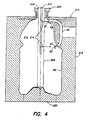
- Fig. 4 is a cross-sectional view of the blow mold, similar to Fig. 3 but later in the process wherein the preform has been expanded to form the container and cooling air is directed out of ports on the stretch rod toward the container engagement portions with the handle;
- Fig. 5 is an air circuit diagram with three air supply and two air exhaust lines as utilized in this embodiment of the blow-molding process.
- Fig. 1 is a graph illustrating a prior art blow-molding process for making a one-gallon PET container. On the vertical Y axis is indicated both the air pressure in psi within the blow mold, and the relative stretch rod position (up and down) in the blow mold. On the horizontal X axis is time in seconds. The graph illustrates one cycle of the blow-molding process. During this cycle a container would be blow-molded from a preform in a blow-molding cavity similar to that shown in Figs. 3-4.
- a preform and handle have been positioned in the blow mold and the blow mold cavity is closed.
- a stretch rod positioned inside the preform (such as shown in Fig. 3) is moved downwardly. This causes axial stretching of the preform, where the preform is at a temperature within the biaxial orientation temperature range for PET.
- low-pressure air is supplied around the stretch rod and within the preform, such that the air pressure within the preform begins to slowly rise and the preform begins to radially expand. The stretch rod continues its downward descent during this second pre-blow stage.
- the stretch rod At 0.6 seconds in the process, the end of the pre-blow stage, the stretch rod has reached its lowest position where the tip of the stretch rod is holding the central bottom portion of the preform against the center of the blow mold base. This helps ensure centering and even expansion of the preform into the container.
- the preform is now partially expanded and has an internal air pressure of 100 to 150 psi (7 - 10.5 bar).
- the process now enters a third stage, the high-pressure blow, at 0.6 seconds.
- a supply of high-pressure air within the preform is increased so that the preform very rapidly radially expands to the final container dimensions. It is then held against the walls of the mold cavity by the high pressure within the cavity. This rapid expansion occurs on the order of 0.2 seconds and the internal pressure reaches 550 to 600 psi 38.7 - 42.2 bar. This pressure is held for about five seconds, during which the fully expanded container is held in contact with the warm walls of the blow mold cavity, in order to thermally condition the container.
- This thermal conditioning increases the amount of crystallization of the PET so as to provide thermal stability when the container is hot-filled.
- the stretch rod remains in its lowermost position holding the center of the container against the center of the blow mold base.
- Fig. 2 shows five stages of the present embodiment with respect to air pressure and stretch rod position over time, as follows: 1. delay 0.4 secs 2. pre-blow 0.2 100-150 psi 7 - 10.5 bar 3. high pressure blow 1.2 550-600 38.7 - 42.2 bar 4. cooling air blow 1.4 450-500 31.5 - 35.2 bar 5. rapid exhaust 0.3
- FIG. 3 shows the preform and handle in the blow mold cavity during the first stage of the process
- Fig. 4 shows the container and handle within the blow mold during the fourth stage wherein cooling air is directed to select portions of the container engaging the handle.
- Fig. 5 is a schematic illustration of three air supply lines and two exhaust lines for accomplishing this embodiment of the blow-molding process.
- a preform and separate handle are positioned within the blow-molding cavity as shown in Fig. 3.
- the preform 10 includes an uppermost neck finish 12 with external threads 14 and a flange 16 at the bottom end of the neck finish.
- a short cylindrical transition (neck finish-to-body) section 18 Below the neck finish there is a short cylindrical transition (neck finish-to-body) section 18, followed by a tapered shoulder or dome-forming portion 20 of increasing thickness.
- the panel-forming section 24 of the preform which is substantially cylindrical and of substantially even thickness.
- a closed base-forming section 26 having an upper tapered section 28 decreasing in wall thickness and a lower generally hemispherical central bottom portion 30.
- the preform of this embodiment is designed in terms of wall thickness, length, width, etc., for making a one-gallon hot-fillable container in accordance with the dimensions defined by the blow-molding cavity.
- the preform is of a single material and layer, and is made of commercially available PET having an intrinsic viscosity of about 0.80.
- the preform 10 is positioned in a blow mold unit 215 with a blow nozzle assembly 200 and stretch rod 208 in place for the start of the blow process.
- the stretch rod 208 has already been extended down into the preform (within the initial delay stage).
- the blow nozzle assembly includes a stuffer (plug) 202 which engages the neck finish of the preform and has an annular bore 204 for supplying fluid pressure to the interior of the preform.
- the blow nozzle assembly further includes a pressure relief valve (not shown) for controlling the fluid pressure within the preform during the various expansion steps.
- the movable stretch rod 208 enhances uniform expansion of the preform.
- the mold unit 215 includes a neck plate 216 which engages the flange 16 just below the neck finish on the preform.
- An upper mold body 218 has an inner surface 219 for forming the sidewall (upper dome, panel and outer base) of the container.
- a lower mold body 220 has an inner surface 221 for forming the central base of the container.
- the mold portions 216, 218 and 220 are kept at various temperatures to ensure appropriate thermal conditioning of the various portions of the container.
- a handle 40 Also positioned within the blow mold is a handle 40.
- the handle is transferred into the blow mold by a transfer arm (not shown but positionable within aperture 225 in the left-hand upper mold body 218).
- the handle is held in place by handle-locating section 223.
- the handle has an upper end 41 with a support platform 44 which includes an annular top flat surface 46, and an annular curved inner surface 45 having a radius about the same as that of an outer wall of the transition portion 18 of the preform, located immediately below the flange 16.
- An upper retaining portion 48 is provided, spaced beneath the support platform 44, and includes a pair of vertically divergent tabs 49, 50 extending toward the longitudinal axis 59 of the preform, container and mold cavity.
- blow molding of the preform causes the plastic material of a portion of the preform wall to be molded about the upper retaining member 48 in order to hold the upper end 41 of the handle against the underside of the flange 16.
- the specific retaining member 48 shown herein is by way of example only; various other attachment members of differing shape, size and location can be utilized as well.
- a lower retaining member 51 At a lower end 47 of the handle, below a central connecting portion 42, is a lower retaining member 51. Member 51 will be incorporated into a lower portion of the container dome by blow-molding of the preform around the lower retaining member 51. Similar to the upper handle retaining portion 48, the lower retaining portion 51 has a diverging distal end 51 in order to secure the handle to the container. Again, this is by way of example only and not limiting.
- the preform 10 is generally hot, e.g., reheated to be within the orientation temperature range of PET, except for the cold neck finish 12.
- the preform will cool as it expands in the mold, and the mold sections 216. 218 and 220 are kept at different temperatures to control the percent crystallinity in different portions of the expanded container.
- the neck plate 216 engaging the neck finish is generally kept at, e.g., 100°F/38°C
- the upper mold body 218 forming the sidewall is kept warm, e.g., 190°F/88°C
- the lower mold body 220 forming the base of the container is kept cooler, e.g., 50°F/10°C .
- the expanded shoulder (dome) and panel sections of the container thus achieve a substantially higher crystallinity level than the base, which optimizes thermal stability in this hot-fillable container.
- Hot-fillable container is described in U.S. Patent No. 4,863,046 to Collette et al., issued September 5, 1989, which is hereby incorporated by reference in its entirety.
- Hot fill containers typically must withstand elevated temperatures on the order of 180-190°F/82-88°C (the product filling temperature) and positive internal pressures on the order of 2-5 psi/0.14 - 0.35 bar (the filling line pressure) without substantial deformation, i.e., a volume change of no greater than about one percent
- the blow-molding cavity is closed (at time "zero") and the blow-molding cycle begins with an initial short delay stage.
- the stretch rod is extended axially downwardly (along vertical axis 59) to axially extend the preform during this stage.
- the stretch rod continues its downward descent while an initial low pressure air supply gradually increases the pressure within the preform up to about 100 to 150 psi/7 - 10.5 bar, over a period of 0.2 seconds.
- a third high-pressure blow stage begins, with an initial rapid expansion of the container up to an internal pressure of 550 to 600 psi/38.7 - 42.2 bar .
- the container is now fully expanded and held in contact with the cavity wall for about 1.2 seconds. Then, in accordance with the present invention, the pressure within the container is reduced to about 450 to 500 psi/31.6 - 35.2 bar, and held for a period of about 1.4 seconds, by supplying a cooling air flow with a slow exhaust. As shown in Fig. 4, this cooling air is supplied via a hollow central axial bore 210 and two air ports 212, 214 within the stretch rod 208; the cooling air is directed by the ports toward the two portions 61, 62 of container 60 which have formed around and tightly engage the upper and low retaining portions 48, 47 of the handle. This enables preferential cooling of these two portions 61, 62 of the container.
- Fig. 5 is an air circuit schematic showing three air supply lines and two exhaust lines for accomplishing the blow-molding process as described herein.
- each supply or exhaust line is provided with a valve 102 which is timed to open and close during the various portions of the cycle.
- all five air lines 104-108 are closed.
- the low-pressure air supply line 104 is open to gradually increase the pressure within the preform and provide an initial radial expansion of the preform.
- all four air lines are closed except for the high-pressure air supply line 105 which supplies high-pressure air to rapidly expand the preform to the final container dimensions, and hold it in contact with the cavity walls for a period of 1.2 seconds.
- all lines are closed except for the cooling air line 106 which supplies high-pressure air to the two ports 212, 214 in the stretch rod, and the slow exhaust line 107 which is open at the same time to exhaust some of the high-pressure air in order to provide an air flow about the two portions 61, 62 of the container being cooled by the cooling air.
- all air lines are closed except for the rapid exhaust line 108 which is opened at the end of the cooling stage in order to reduce the pressure within the container down to zero (ambient), before opening the mold.
- blow-molding process time there is achieved an overall reduction in the blow-molding process time, as well as an improved anchoring of the handle to the container.
- the reduction in blow-molding process time is quite significant in the present embodiment, which is seen by comparing Figs. 1 and 2.
- the blow-molding process time was 5.9 seconds, whereas in the embodiment of the present invention, the blow-molding process time has been reduced to 3.5 seconds. This is a very significant cost savings in the manufacture of the container.
- the low pressure pro-blow stage is eliminated. This would eliminate the need for the low pressure air supply line. Generally, however, the pro-blow stage is preferred because it improves the material distribution In the container.
- a separate source of cooling air can be eliminated; instead, the high pressure source is utilized during the fourth cooling air blow stage, while opening of the slow exhaust line achieves the desired reduction in air pressure and air flow.
- additional cooling of the handle can be achieved by circulating cooling media in the handle locating section 223 of the blow mold.
- the retaining members on the handle may be of different size, shape and location.
- the goal is to achieve a secure connection between the container wall and retaining members, typically by allowing the container wall to conform to the external contour of the retaining member, and also to reduce post-mold deformation at these portions of the container wall by adequately cooling down the wall material to its rigid state within the blow mold.
- the container is not limited to either monolayer containers or PET containers.
- Various other polymer resins can be used such as polyesters (in addition to PET), polyolefins, polycarbonates, nitriles, and copolymers of the same.
- Polyethylene naphthalate (PEN) is another useful polymer with physical properties similar to PET, but provides an improvement in barrier property and thermal performance.
- the container may either be a monolayer or multilayer construction, including layers of for example an oxygen barrier material, a layer of reprocessed scrap material, or other high-performance materials.
- the container may not be a hot-fillable container, but rather can be a carbonated beverage container, juice container, ketchup container, liquid detergent container, etc.
- the handle may be formed by any well-known technique, such as injection molding. It is not necessary that it is made from the same material as the container. It may be formed from a plastic such as high-density polyethylene, polypropylene, PET, recycled PET, glass reinforced PET or glass reinforced high-density polyethylene.
Landscapes
- Engineering & Computer Science (AREA)
- Manufacturing & Machinery (AREA)
- Mechanical Engineering (AREA)
- Physics & Mathematics (AREA)
- Thermal Sciences (AREA)
- Blow-Moulding Or Thermoforming Of Plastics Or The Like (AREA)
- Moulds For Moulding Plastics Or The Like (AREA)
Abstract
Description
| 1. | delay | 0.4 secs | |
| 2. | pre-blow | 0.2 | 100-150 psi 7 - 10.5 bar |
| 3. | high pressure blow | 5.0 | 550-600 38.7 - 42.2 bar |
| 4. | | 0,3 |
| 1. | delay | 0.4 secs | |
| 2. | pre-blow | 0.2 | 100-150 psi 7 - 10.5 bar |
| 3. | high pressure blow | 1.2 | 550-600 38.7 - 42.2 bar |
| 4. | cooling air blow | 1.4 | 450-500 31.5 - 35.2 bar |
| 5. | rapid exhaust | 0.3 |
Claims (19)
- A method of in-mold handle attachment, including steps of:characterized by directing a cooling medium (106) at the location of the container portion (61, 62) in order to accelerate the cooling rate of the container portion (61, 62) about the handle (40).expanding a preform (10) in a blow mold (215) to form a blow-molded container (60), wherein a portion (61, 62) of the blow-molded container (60) is formed about a handle (40) during blow-molding,
- The method of claim 1
wherein the cooling medium is air directed at the portion (61, 62) from within the blow-molded container (60). - The method of claim 1 or 2,
wherein the blow-molded container (60) is axially stretched by a stretch rod (208) and wherein the stretch rod (208) includes at least one port (212, 214) for directing the cooling medium at the container portion (61, 62). - The method of any of claims 1 to 3,
wherein the cooling medium is directed at the container portion (61, 62) while the container (60) is held against the mold cavity (219). - The method of any of claims 1 to 4,
wherein a partial exhaust (107) is provided for promoting flow of the cooling medium. - The method of claim 5,
wherein directing the cooling medium (106) and applying the partial exhaust (107) is followed by applying a rapid exhaust (108). - The method of claim 1,
wherein the directing step reduces the time for cooling the blow-molded container (60) in the blow mold. - The method of any of claims 1 to 7,
wherein a high pressure source (105) supplies the cooling medium. - The method of any of claims 1 to 7,
wherein a high pressure source (105) supplies an expansion medium for the expanding step and the cooling medium for the directing step. - The method of any of claims 1 to 9,
wherein a low pressure source (104) supplies an expansion medium during a preliminary expansion step. - The method of any of claims 1 to 10,
wherein a slow exhaust (107) is provided to promote flow of the cooling medium and a rapid exhaust (108) is provided for exhausting an expansion medium. - The method of claim 5 and 6,
wherein the step of applying the cooling medium (106) and partial exhaust (107) is followed by applying a rapid exhaust (108) prior to removal of the container (60) from the mold cavity (219). - The method of any of claims 1 to 12,
wherein the portion (61, 62) of the blow-molded container (60) is formed about a retaining member (47, 48) on the handle (40) during blow-molding in the mold cavity (219). - A blow-molding apparatus comprising
a stretch rod (208) and blow-molding cavity (219),
characterized in that
the stretch rod (208) has at least one port (212, 214) for directing a cooling medium (106) against a portion (61, 62) of a blow-molded container (60)formed about a handle (40) in the blow-molding cavity (219). - The apparatus of claim 14, including a partial exhaust (107) for promoting flow of the cooling medium (106) at the container portion.
- The apparatus of claim 14 or 15, including
at least one high-pressure source (105) for supplying an expansion medium during blow-molding and for supplying the cooling medium; and
an exhaust promoting a flow of the cooling medium in the blow-molding cavity (219). - The apparatus of claim 16, including at least one low-pressure source (104) for supplying a low-pressure expansion medium during a preliminary expansion step.
- The apparatus of any of claims 14 to 17,
wherein the exhaust includes a slow exhaust (107) for promoting flow of the cooling medium and a rapid exhaust (108) for exhausting the blow-molding expansion medium. - A stretch rod (208) for use in a blow-molding cavity (219), the stretch rod (208) including at least one port (212, 214) located at at least one select location for directing a cooling medium against a portion (61, 62) of a blow-molded container (60) formed about a handle (40) in the blow-molding cavity (219).
Applications Claiming Priority (2)
| Application Number | Priority Date | Filing Date | Title |
|---|---|---|---|
| US09/994,555 US6855289B2 (en) | 2001-11-27 | 2001-11-27 | Method and apparatus for cooling during in-mold handle attachment |
| US994555 | 2001-11-27 |
Publications (1)
| Publication Number | Publication Date |
|---|---|
| EP1314535A1 true EP1314535A1 (en) | 2003-05-28 |
Family
ID=25540794
Family Applications (1)
| Application Number | Title | Priority Date | Filing Date |
|---|---|---|---|
| EP02026174A Withdrawn EP1314535A1 (en) | 2001-11-27 | 2002-11-25 | Method and apparatus for blowmolding, in particular inside cooling during in-mold handle attachment |
Country Status (6)
| Country | Link |
|---|---|
| US (2) | US6855289B2 (en) |
| EP (1) | EP1314535A1 (en) |
| JP (1) | JP2003231171A (en) |
| CA (1) | CA2412364C (en) |
| MX (1) | MXPA02011666A (en) |
| NZ (2) | NZ522763A (en) |
Cited By (10)
| Publication number | Priority date | Publication date | Assignee | Title |
|---|---|---|---|---|
| WO2005097466A1 (en) * | 2004-04-08 | 2005-10-20 | Sig Technology Ltd. | Method and device for blow-forming containers using a reduced pressure increasing speed |
| EP1616688A2 (en) * | 2004-07-14 | 2006-01-18 | Delta Engineering | Method for blow moulding objects |
| DE102004050531A1 (en) * | 2004-10-16 | 2006-04-20 | Sig Technology Ltd. | Plastic container blow molding process involves limiting pressure rate rise in container within a specified pressure range |
| WO2008000704A2 (en) * | 2006-06-29 | 2008-01-03 | Techne Technipack Engineering Italia S.P.A. | Method and equipment for cooling blow moulded or thermoformed articles |
| GB2444038A (en) * | 2006-11-22 | 2008-05-28 | Plastic Can Company Ltd | Method and apparatus for moulding a container with a handle |
| FR2939070A1 (en) * | 2008-12-03 | 2010-06-04 | Sidel Participations | FORMING THE CONTAINERS WITH LOCALIZED COOLING |
| US8550805B2 (en) | 2004-03-25 | 2013-10-08 | Krones Ag | Process and device for the manufacture of a particularly heat-resistant hollow body |
| WO2015136368A3 (en) * | 2014-03-10 | 2015-12-23 | Discma Ag | Method of forming and setting headspace within a container |
| EP1660301B1 (en) | 2003-09-05 | 2016-11-02 | KHS Corpoplast GmbH | Method and device for blow-forming containers |
| WO2019211557A1 (en) * | 2018-05-02 | 2019-11-07 | Sidel Participations | Method for forming a container made of thermoplastic material by biaxial stretching |
Families Citing this family (27)
| Publication number | Priority date | Publication date | Assignee | Title |
|---|---|---|---|---|
| GB2380967B (en) * | 2001-09-28 | 2003-12-24 | Roton Compressor Services Ltd | Blow moulding control system |
| TW200412287A (en) * | 2003-01-02 | 2004-07-16 | Ming-Jie You | Method for blow molding a container with handle |
| US7264464B2 (en) * | 2003-06-09 | 2007-09-04 | Husky Injection Molding Systems Ltd. | Cooling tube with a low friction coating |
| DE10340915A1 (en) * | 2003-09-05 | 2005-03-31 | Sig Technology Ltd. | Method and device for blow-molding workpieces |
| ITRE20040128A1 (en) * | 2004-10-12 | 2005-01-12 | Sacmi | GROUP FOR THE COMPRESSION FORMING OF OBJECTS IN POLYMERIC MATERIAL |
| US7637733B2 (en) * | 2004-12-02 | 2009-12-29 | Graham Packaging Company, L.P. | Method and apparatus for reforming a portion of a plastic container to include a three-dimensional feature or transferable element |
| US20070126152A1 (en) * | 2005-12-06 | 2007-06-07 | Graham Packaging Company, L.P. | Methods and apparatuses for reforming an upper portion of a blow molded plastic container |
| US7600655B2 (en) * | 2006-05-10 | 2009-10-13 | Graham Packaging Company, Llp | Anchor for attachment of a handle to a container |
| EP2143653B1 (en) * | 2007-03-30 | 2020-05-27 | Yoshino Kogyosho Co., Ltd. | Bottle with handle made of synthetic resin |
| JP5082900B2 (en) * | 2008-02-07 | 2012-11-28 | 東洋製罐株式会社 | Method for producing a synthetic resin container having handle pieces connected thereto |
| DE102008013419A1 (en) * | 2008-03-06 | 2009-09-10 | Khs Corpoplast Gmbh & Co. Kg | Method and apparatus for blow molding containers |
| PL2416938T3 (en) | 2009-04-07 | 2015-03-31 | Graham Packaging Co | Method and apparatus for reforming a portion of a plastic container using induction heating |
| US8734709B2 (en) | 2009-04-07 | 2014-05-27 | Graham Packaging Company, L.P. | Apparatus for reforming a portion of a plastic container |
| US9023446B2 (en) * | 2009-09-22 | 2015-05-05 | Graham Packaging Lc, L.P. | PET containers with enhanced thermal properties and process for making same |
| US8741206B2 (en) * | 2009-12-17 | 2014-06-03 | Eastman Chemical Company | Method and apparatus for stretch blow molding a container |
| US8647559B2 (en) * | 2010-03-10 | 2014-02-11 | GM Global Technology Operations LLC | Method for producing a liner of a container |
| KR101390703B1 (en) | 2012-02-23 | 2014-04-30 | 새한프라텍 주식회사 | Pet bottle handle attaching method |
| CN104837604B (en) * | 2012-12-14 | 2017-06-20 | 日精Asb机械株式会社 | Container mold with handles, the manufacture method of container with handles and container with handles |
| CN105307835B (en) * | 2013-06-28 | 2017-12-19 | 日精Asb机械株式会社 | The building mortion of container with handles and molding die and molding die unit for the device |
| US9505163B2 (en) * | 2014-01-21 | 2016-11-29 | Dt Inventions, Llc | Manufacturing method and device for a container with an integral handle |
| US9962881B2 (en) * | 2014-09-19 | 2018-05-08 | R&D Tool & Engineering Co. | Tooling and process for injection stretch blow molded container with integral handle |
| US9725802B2 (en) | 2014-11-11 | 2017-08-08 | Graham Packaging Company, L.P. | Method for making pet containers with enhanced silicon dioxide barrier coating |
| CN104476758A (en) * | 2014-11-20 | 2015-04-01 | 中山汇伟塑胶工业有限公司 | Local cooling mechanism for preform molding |
| JP6843453B2 (en) * | 2018-10-11 | 2021-03-17 | 株式会社青木固研究所 | Stretch blow molding equipment and blow molding method |
| US11161293B2 (en) * | 2020-02-10 | 2021-11-02 | Dt Inventions | Blow nozzle with holes for directional blowing |
| WO2022056958A1 (en) * | 2020-09-17 | 2022-03-24 | 广州达意隆包装机械股份有限公司 | Heat treatment device for pet bottle preform having handle |
| WO2024028687A1 (en) * | 2022-08-04 | 2024-02-08 | Pibiplast S.P.A. | Method for forming a container |
Citations (6)
| Publication number | Priority date | Publication date | Assignee | Title |
|---|---|---|---|---|
| US4128383A (en) * | 1976-05-24 | 1978-12-05 | The Standard Oil Company | Apparatus for controlling plastic material distribution in manufacture of biaxially oriented plastic containers |
| JPH04138241A (en) * | 1990-09-29 | 1992-05-12 | Nissei Asb Mach Co Ltd | Molding method for hollow container with handle |
| US5182122A (en) * | 1989-08-31 | 1993-01-26 | Nissei Asb Machine Co., Ltd. | Apparatus for stretch blow molding hollow heat-resistant container |
| JPH05261799A (en) * | 1992-03-17 | 1993-10-12 | Denki Kagaku Kogyo Kk | Method for molding resin hollow container |
| JPH0768629A (en) * | 1993-09-06 | 1995-03-14 | Mitsubishi Plastics Ind Ltd | Molding method for bottle with grip |
| JPH08300452A (en) * | 1995-05-02 | 1996-11-19 | Mitsubishi Plastics Ind Ltd | Production of handled polyester bottle |
Family Cites Families (10)
| Publication number | Priority date | Publication date | Assignee | Title |
|---|---|---|---|---|
| US4863046A (en) | 1987-12-24 | 1989-09-05 | Continental Pet Technologies, Inc. | Hot fill container |
| AU642962B2 (en) * | 1990-02-16 | 1993-11-04 | Sekisui Kaseihin Kogyo Kabushiki Kaisha | Process of producing thermoplastic polyester series resin foamed material |
| ATE134564T1 (en) * | 1990-04-12 | 1996-03-15 | Mitsubishi Plastics Inc | METHOD FOR PRODUCING A BOTTLE WITH HANDLE |
| US5281387A (en) | 1992-07-07 | 1994-01-25 | Continental Pet Technologies, Inc. | Method of forming a container having a low crystallinity |
| US5469612A (en) | 1993-12-02 | 1995-11-28 | Continental Pet Technologies, Inc. | Method for forming a strain-hardenable plastic container |
| US5704503A (en) | 1994-10-28 | 1998-01-06 | Continental Pet Technologies, Inc. | Hot-fillable plastic container with tall and slender panel section |
| AUPM941794A0 (en) | 1994-11-15 | 1994-12-08 | Aci Operations Pty. Limited | Handled plastic container |
| AUPN981796A0 (en) | 1996-05-14 | 1996-06-06 | Aci Operations Pty. Limited | Handled plastic container |
| US6444158B1 (en) * | 1996-05-14 | 2002-09-03 | Continental Pet Technologies, Inc. | Handled plastic container |
| US6012597A (en) | 1998-03-18 | 2000-01-11 | Mitsubishi Plastics, Inc. | Polyester bottle with a handle and method of manufacturing the same |
-
2001
- 2001-11-27 US US09/994,555 patent/US6855289B2/en not_active Expired - Lifetime
-
2002
- 2002-11-22 CA CA002412364A patent/CA2412364C/en not_active Expired - Fee Related
- 2002-11-25 EP EP02026174A patent/EP1314535A1/en not_active Withdrawn
- 2002-11-25 NZ NZ522763A patent/NZ522763A/en not_active IP Right Cessation
- 2002-11-25 NZ NZ534759A patent/NZ534759A/en unknown
- 2002-11-26 MX MXPA02011666A patent/MXPA02011666A/en active IP Right Grant
- 2002-11-27 JP JP2002382719A patent/JP2003231171A/en active Pending
-
2005
- 2005-02-11 US US11/056,218 patent/US20050136149A1/en not_active Abandoned
Patent Citations (6)
| Publication number | Priority date | Publication date | Assignee | Title |
|---|---|---|---|---|
| US4128383A (en) * | 1976-05-24 | 1978-12-05 | The Standard Oil Company | Apparatus for controlling plastic material distribution in manufacture of biaxially oriented plastic containers |
| US5182122A (en) * | 1989-08-31 | 1993-01-26 | Nissei Asb Machine Co., Ltd. | Apparatus for stretch blow molding hollow heat-resistant container |
| JPH04138241A (en) * | 1990-09-29 | 1992-05-12 | Nissei Asb Mach Co Ltd | Molding method for hollow container with handle |
| JPH05261799A (en) * | 1992-03-17 | 1993-10-12 | Denki Kagaku Kogyo Kk | Method for molding resin hollow container |
| JPH0768629A (en) * | 1993-09-06 | 1995-03-14 | Mitsubishi Plastics Ind Ltd | Molding method for bottle with grip |
| JPH08300452A (en) * | 1995-05-02 | 1996-11-19 | Mitsubishi Plastics Ind Ltd | Production of handled polyester bottle |
Non-Patent Citations (4)
| Title |
|---|
| PATENT ABSTRACTS OF JAPAN vol. 016, no. 410 (M - 1302) 28 August 1992 (1992-08-28) * |
| PATENT ABSTRACTS OF JAPAN vol. 018, no. 025 (M - 1542) 14 January 1994 (1994-01-14) * |
| PATENT ABSTRACTS OF JAPAN vol. 1995, no. 06 31 July 1995 (1995-07-31) * |
| PATENT ABSTRACTS OF JAPAN vol. 1997, no. 03 31 March 1997 (1997-03-31) * |
Cited By (22)
| Publication number | Priority date | Publication date | Assignee | Title |
|---|---|---|---|---|
| EP1660301B2 (en) † | 2003-09-05 | 2021-06-16 | KHS Corpoplast GmbH | Method and device for blow-forming containers |
| EP1660301B1 (en) | 2003-09-05 | 2016-11-02 | KHS Corpoplast GmbH | Method and device for blow-forming containers |
| US9044892B2 (en) | 2004-03-25 | 2015-06-02 | Krones Ag | Process and device for the manufacture of a particularly heat-resistant hollow body |
| US8550805B2 (en) | 2004-03-25 | 2013-10-08 | Krones Ag | Process and device for the manufacture of a particularly heat-resistant hollow body |
| WO2005097466A1 (en) * | 2004-04-08 | 2005-10-20 | Sig Technology Ltd. | Method and device for blow-forming containers using a reduced pressure increasing speed |
| EP1616688A2 (en) * | 2004-07-14 | 2006-01-18 | Delta Engineering | Method for blow moulding objects |
| EP1616688A3 (en) * | 2004-07-14 | 2009-10-07 | Delta Engineering | Method for blow moulding objects |
| DE102004050531A1 (en) * | 2004-10-16 | 2006-04-20 | Sig Technology Ltd. | Plastic container blow molding process involves limiting pressure rate rise in container within a specified pressure range |
| WO2008000704A2 (en) * | 2006-06-29 | 2008-01-03 | Techne Technipack Engineering Italia S.P.A. | Method and equipment for cooling blow moulded or thermoformed articles |
| WO2008000704A3 (en) * | 2006-06-29 | 2008-04-10 | Techne Technipack Engineering | Method and equipment for cooling blow moulded or thermoformed articles |
| GB2444038A (en) * | 2006-11-22 | 2008-05-28 | Plastic Can Company Ltd | Method and apparatus for moulding a container with a handle |
| CN102239039B (en) * | 2008-12-03 | 2014-10-29 | 西德尔合作公司 | Method and device for forming containers with localized cooling |
| US9061458B2 (en) | 2008-12-03 | 2015-06-23 | Sidel Participations | Method and device for forming containers with localized cooling |
| WO2010063899A1 (en) * | 2008-12-03 | 2010-06-10 | Sidel Participations | Method and device for forming containers with localized cooling |
| FR2939070A1 (en) * | 2008-12-03 | 2010-06-04 | Sidel Participations | FORMING THE CONTAINERS WITH LOCALIZED COOLING |
| WO2015136368A3 (en) * | 2014-03-10 | 2015-12-23 | Discma Ag | Method of forming and setting headspace within a container |
| WO2015136369A3 (en) * | 2014-03-10 | 2016-04-14 | Discma Ag | Method of forming and setting headspace within a container |
| EP3202550A1 (en) * | 2014-03-10 | 2017-08-09 | Discma AG | Method of forming and setting headspace within a container |
| US10363699B2 (en) | 2014-03-10 | 2019-07-30 | Discma Ag | Method of forming and setting headspace within a container |
| WO2019211557A1 (en) * | 2018-05-02 | 2019-11-07 | Sidel Participations | Method for forming a container made of thermoplastic material by biaxial stretching |
| FR3080795A1 (en) * | 2018-05-02 | 2019-11-08 | Sidel Participations | PROCESS FOR FORMING A CONTAINER IN THERMOPLASTIC MATERIAL BY BI-AXIAL STRETCHING |
| EP3787870B1 (en) | 2018-05-02 | 2022-03-16 | Sidel Participations | Method for forming a container made of thermoplastic material by biaxial stretching |
Also Published As
| Publication number | Publication date |
|---|---|
| MXPA02011666A (en) | 2004-09-03 |
| NZ522763A (en) | 2004-10-29 |
| US6855289B2 (en) | 2005-02-15 |
| NZ534759A (en) | 2006-04-28 |
| CA2412364A1 (en) | 2003-05-27 |
| JP2003231171A (en) | 2003-08-19 |
| US20050136149A1 (en) | 2005-06-23 |
| US20030098526A1 (en) | 2003-05-29 |
| CA2412364C (en) | 2008-02-05 |
Similar Documents
| Publication | Publication Date | Title |
|---|---|---|
| US6855289B2 (en) | Method and apparatus for cooling during in-mold handle attachment | |
| CA2593927C (en) | A process for forming a container by stretch blow molding and container formed thereby | |
| US5622735A (en) | Fluid supply apparatus for blow mold | |
| US4629598A (en) | Method for forming plastic bottle with integral handle | |
| CN101115606B (en) | Method for manufacturing containers through stretching and blow-molding and the containers manufactured thereof | |
| AU2011316513B2 (en) | Blow nozzle to control liquid flow with pre-stretch rod assembly | |
| US20210245415A1 (en) | Blow nozzle with holes for directional blowing | |
| US4850850A (en) | Apparatus for preparing heat-set plastic hollow vessel | |
| JPS6158288B2 (en) | ||
| US10246238B2 (en) | Plastic container having a deep-set invertible base and related methods | |
| JP4292918B2 (en) | Preforms for plastic bottle containers | |
| JP4210901B2 (en) | Manufacturing method of bottle-shaped container | |
| AU2005252227A1 (en) | Stretched container and method of manufacture | |
| JPH0546300B2 (en) | ||
| JP4333280B2 (en) | Plastic bottle containers | |
| JP4148065B2 (en) | Stretch blow molding method of plastic bottle container and plastic bottle container formed by this molding method | |
| JP2911557B2 (en) | Resin preform, biaxially stretch blow-molded container using the same, and method for producing the same | |
| JP2003103607A (en) | Bottom structure of heat-resistant bottle | |
| JPH07156259A (en) | Manufacture of resin hollow vessel | |
| JPH06262670A (en) | Polyester container having drum part partially defferent in degree of crystallization and production thereof | |
| AU684390B2 (en) | A stretch blow moulded threaded container | |
| AU673467C (en) | Pulse blow method and apparatus for forming container with enhanced thermal stability | |
| JPH0760825A (en) | Manufacture of resin hollow vessel |
Legal Events
| Date | Code | Title | Description |
|---|---|---|---|
| PUAI | Public reference made under article 153(3) epc to a published international application that has entered the european phase |
Free format text: ORIGINAL CODE: 0009012 |
|
| AK | Designated contracting states |
Designated state(s): AT BE BG CH CY CZ DE DK EE ES FI FR GB GR IE IT LI LU MC NL PT SE SK TR |
|
| AX | Request for extension of the european patent |
Extension state: AL LT LV MK RO SI |
|
| 17P | Request for examination filed |
Effective date: 20031106 |
|
| 17Q | First examination report despatched |
Effective date: 20040105 |
|
| AKX | Designation fees paid |
Designated state(s): AT BE BG CH CY CZ DE DK EE ES FI FR GB GR IE IT LI LU MC NL PT SE SK TR |
|
| 17Q | First examination report despatched |
Effective date: 20040105 |
|
| STAA | Information on the status of an ep patent application or granted ep patent |
Free format text: STATUS: THE APPLICATION IS DEEMED TO BE WITHDRAWN |
|
| 18D | Application deemed to be withdrawn |
Effective date: 20090603 |