EP1312864A1 - Kraftstoffdosierungsvorrichtung für die Einspritzdüse einer Turbomaschine - Google Patents
Kraftstoffdosierungsvorrichtung für die Einspritzdüse einer Turbomaschine Download PDFInfo
- Publication number
- EP1312864A1 EP1312864A1 EP02292879A EP02292879A EP1312864A1 EP 1312864 A1 EP1312864 A1 EP 1312864A1 EP 02292879 A EP02292879 A EP 02292879A EP 02292879 A EP02292879 A EP 02292879A EP 1312864 A1 EP1312864 A1 EP 1312864A1
- Authority
- EP
- European Patent Office
- Prior art keywords
- fuel
- fluid
- metering
- valve
- orifice
- Prior art date
- Legal status (The legal status is an assumption and is not a legal conclusion. Google has not performed a legal analysis and makes no representation as to the accuracy of the status listed.)
- Granted
Links
- 239000000446 fuel Substances 0.000 title claims abstract description 81
- 239000012530 fluid Substances 0.000 claims abstract description 47
- 238000000034 method Methods 0.000 claims description 4
- 238000002485 combustion reaction Methods 0.000 description 7
- 238000004401 flow injection analysis Methods 0.000 description 1
- 238000007789 sealing Methods 0.000 description 1
- 238000005507 spraying Methods 0.000 description 1
- 238000011144 upstream manufacturing Methods 0.000 description 1
- 238000009834 vaporization Methods 0.000 description 1
- 230000008016 vaporization Effects 0.000 description 1
Images


Classifications
-
- F—MECHANICAL ENGINEERING; LIGHTING; HEATING; WEAPONS; BLASTING
- F23—COMBUSTION APPARATUS; COMBUSTION PROCESSES
- F23K—FEEDING FUEL TO COMBUSTION APPARATUS
- F23K5/00—Feeding or distributing other fuel to combustion apparatus
- F23K5/02—Liquid fuel
- F23K5/14—Details thereof
- F23K5/147—Valves
-
- F—MECHANICAL ENGINEERING; LIGHTING; HEATING; WEAPONS; BLASTING
- F16—ENGINEERING ELEMENTS AND UNITS; GENERAL MEASURES FOR PRODUCING AND MAINTAINING EFFECTIVE FUNCTIONING OF MACHINES OR INSTALLATIONS; THERMAL INSULATION IN GENERAL
- F16K—VALVES; TAPS; COCKS; ACTUATING-FLOATS; DEVICES FOR VENTING OR AERATING
- F16K17/00—Safety valves; Equalising valves, e.g. pressure relief valves
- F16K17/02—Safety valves; Equalising valves, e.g. pressure relief valves opening on surplus pressure on one side; closing on insufficient pressure on one side
- F16K17/04—Safety valves; Equalising valves, e.g. pressure relief valves opening on surplus pressure on one side; closing on insufficient pressure on one side spring-loaded
-
- F—MECHANICAL ENGINEERING; LIGHTING; HEATING; WEAPONS; BLASTING
- F23—COMBUSTION APPARATUS; COMBUSTION PROCESSES
- F23D—BURNERS
- F23D2206/00—Burners for specific applications
- F23D2206/10—Turbines
-
- Y—GENERAL TAGGING OF NEW TECHNOLOGICAL DEVELOPMENTS; GENERAL TAGGING OF CROSS-SECTIONAL TECHNOLOGIES SPANNING OVER SEVERAL SECTIONS OF THE IPC; TECHNICAL SUBJECTS COVERED BY FORMER USPC CROSS-REFERENCE ART COLLECTIONS [XRACs] AND DIGESTS
- Y10—TECHNICAL SUBJECTS COVERED BY FORMER USPC
- Y10T—TECHNICAL SUBJECTS COVERED BY FORMER US CLASSIFICATION
- Y10T137/00—Fluid handling
- Y10T137/7722—Line condition change responsive valves
- Y10T137/7837—Direct response valves [i.e., check valve type]
- Y10T137/7838—Plural
- Y10T137/7839—Dividing and recombining in a single flow path
-
- Y—GENERAL TAGGING OF NEW TECHNOLOGICAL DEVELOPMENTS; GENERAL TAGGING OF CROSS-SECTIONAL TECHNOLOGIES SPANNING OVER SEVERAL SECTIONS OF THE IPC; TECHNICAL SUBJECTS COVERED BY FORMER USPC CROSS-REFERENCE ART COLLECTIONS [XRACs] AND DIGESTS
- Y10—TECHNICAL SUBJECTS COVERED BY FORMER USPC
- Y10T—TECHNICAL SUBJECTS COVERED BY FORMER US CLASSIFICATION
- Y10T137/00—Fluid handling
- Y10T137/7722—Line condition change responsive valves
- Y10T137/7837—Direct response valves [i.e., check valve type]
- Y10T137/7866—Plural seating
- Y10T137/7867—Sequential
Definitions
- the present invention relates to the general field of devices for adjusting the flow rate of a fluid, and more particularly to that devices for adjusting the feed rate of the injectors fuel intended for the combustion chambers of turbomachinery.
- a turbomachine engine comprises several injectors for supplying fuel and air to the combustion chamber during start-up and normal operation of the turbomachine engine.
- injectors for supplying fuel and air to the combustion chamber during start-up and normal operation of the turbomachine engine.
- injectors there are two types injectors: so-called “aeromechanical” injectors designed for two fuel flows (primary and secondary) according to the phases of engine operation (ignition, low to full power), and so-called “aerodynamic” injectors which have only one circuit fuel for all operating phases.
- the current the invention relates more particularly to the injectors belonging to this second category.
- an engine fuel injector of a turbomachine in particular comprises a metering valve arranged to open under fuel supply pressure predetermined and stay open in response to an increase in this supply pressure to allow fuel to be admitted and its ejection to the injector nose at which the fuel is diffused into the combustion chamber.
- Feed rate adjustment fuel is produced by means of metering slots provided at a valve head and whose passage cross-sections vary depending on the supply pressure applied: the higher this pressure The higher the cross sections of the slots.
- the present invention therefore aims to overcome such drawbacks by proposing a fluid metering device for a turbomachine injector which suppresses the effects caused by hysteresis by using the dead stroke of the valve head, i.e. the stroke between the start opening time and when the slots are reached dosage. It further relates to a fluid metering process using works such a device.
- a fluid metering device comprising a metering valve which can slide in a socket under a fluid supply pressure to allow admission of fluid then its ejection to means of using this fluid, the valve having at one end an opening opening into a longitudinal bore for fluid intake and at a second end forming the bottom of a valve head provided with fluid dosing slots opening into the longitudinal bore and defining sections of variable passage to said means for using the fluid, characterized in that said valve head further comprises at least one orifice substantially transverse disposed downstream of the metering slots in the direction of flow of the fluid, said orifice communicating with the bore longitudinal and defining at least one fixed passage section towards said means for using the fluid.
- the device thus makes it possible to obtain a fixed flow of fluid towards the means of use which depends only on the passage section of the transverse hole. This leads to the means of use at from a predetermined fluid supply pressure which is less than a pressure at which the metering slots feed the means of use. In this way, any delay due to the phenomenon hysteresis and leading to heterogeneity of supply is avoided. Hysteresis therefore no longer has an effect on low flow rates.
- the metering device has a first diaphragm disposed upstream of the transverse orifice in the direction of fluid flow.
- This first diaphragm allows set the flow rate of fluid passing through the orifice to a determined value transverse.
- the fluid metering device according to the invention finds particularly applicable as a fuel metering device injector for a turbomachine engine.
- hysteresis no longer has an effect on low flow rates and a better homogeneity of fuel supply in the combustion of the engine, especially during the delicate ignition phase of the motor.
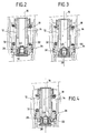
- Figure 1 shows in section longitudinal a fuel injector for a turbomachine engine comprising a metering device according to the invention.
- the fuel injector 2 includes an injector body 4 comprising a flange 6 adapted to be fixed on a body of turbomachine (not shown).
- the fuel injector 2 illustrated is of the "aerodynamic" type, ie it has only one circuit of fuel.
- the injector body 4 has an inlet port 8 of fuel for receiving pressurized fuel from a suitable pump (not shown).
- the fuel comes out in an intake chamber 10 before passing through a metering device 12 according to the invention.
- the fuel metering device 12 is mounted directly into the fuel intake chamber 10. It includes a valve metering 14 for controlling the flow of fuel passing through the device.
- This metering valve has a first end an opening 16 opening into a longitudinal bore 18 fuel intake, and at a second end, forming the bottom, a substantially circular shoulder forming the valve head 20.
- This valve head has metering slots 22 around its periphery fuel opening into the longitudinal bore 18 and defining variable passage sections towards means of using the combustible. These slots 22 are shaped very precisely for metering the quantity of fuel flowing from the intake chamber 10 to a fuel receiving chamber 24 formed in the body injector 4.
- the metering valve 14 can slide in a socket 26 cylindrical, one end of which has a circular recess 28 forming valve seat.
- This socket is held in the body of injector 4 in a sealed manner by means of a sealing means 30 of the joint type.
- the bush 26 also forms a bearing surface for one end of a helical spring 32 whose opposite end is mounted in an annular retaining element 34 fixed on the end of the valve comprising the longitudinal bore 18 of fuel intake.
- the spring 32 is adjusted so as to allow the metering valve 14 to open for a predetermined fuel pressure and to remain open under the increase of this supply pressure.
- the metering device 12 is further provided with at least one substantially transverse orifice 38 disposed at the level of the head valve 20, downstream of the metering slots 22 in the direction fuel flow.
- This transverse opening opens into the longitudinal bore 18 of fluid intake and communicates with the fuel receiving chamber 24.
- This orifice thus allows define a fixed passage section towards the means of use of the fuel and effectively ensure the ignition rate of the engine of the turbomachine corresponding to the low fuel flow rates (less than 30 liters per hour approximately).
- the flow of fuel passing through the transverse orifice 38 can advantageously be fixed to a first value determined by placing a first diaphragm 40 in the path of the fuel, between the longitudinal bore and this transverse orifice.
- the passage of fuel is thus controlled by the opening made on the first diaphragm 40.
- This opening is shaped so as to allow a significantly lower fuel flow through it than that crossing the transverse orifice 38.
- the flow of fuel passing through the first diaphragm 40 then the transverse orifice 38 is only a function of the opening made on this first diaphragm. This characteristic is particularly advantageous for very low fuel flow rates.
- the first diaphragm 40 thus avoids a such operation.
- the first diaphragm 40 can for example be a bowl drilled mounted tight in the bottom of the valve head 20.
- the fuel injector shown in Figure 1 includes a second diaphragm 42 for large flows (greater than 100 liters) per hour approximately) interposed between the metering valve 14 and the means fuel use. More precisely, this second diaphragm 42 also in the form of a pierced bowl is arranged at the bottom of the 24 fuel reception.
- the second diaphragm is fixed so watertight on the injector body 4 by means seal 44 of the joint type and allows fixing at a second value determined the fuel flow through it.
- the opening on this second diaphragm opens into an ejection channel 46 of the fuel which directs it towards an injector nose (not shown). AT using means known per se, this injector nose ensures either spraying fuel mechanically or aerodynamically, either its vaporization.
- FIG. 2 represents the fuel metering device in initial rest position; the metering valve 14 is closed and rests on its seat 28. Fuel entering the intake chamber 10 and in the longitudinal bore 18 via the opening 16 exerts a pressure which is not sufficient to allow the opening of the metering valve.
- Figure 3 illustrates the metering device when a pressure predetermined defining a first threshold pressure S1 is reached.
- the metering valve 14 moves under the effect of the supply pressure and slides in the socket 26 causing a opening of the valve head 20.
- the fuel present in the inlet chamber 10 and into the metering valve 14 spring out into the receiving chamber 24 via the transverse orifice 38 after passing through the first diaphragm 40.
- This phase can by example correspond to the ignition phase of a turbomachine equipped with this metering device.
- the fuel flow is fixed and is a function of either the cross section of the transverse orifice 38, or of the opening made on the first diaphragm 40 if the latter is weaker.
- the metering device is in a position of semi-opening for which the supply pressure is greater than a second threshold pressure S2, which is itself greater than the first threshold pressure S1.
- This second threshold pressure S2 corresponds to a predetermined supply pressure from which the metering slots 22 of the valve head 20 open out in the reception chamber 24.
- the spring 32 compresses under the effect of the supply pressure and the fuel continues to pass through the metering valve 14 via the transverse orifice 38.
- the fuel present in the bore 18 of the metering valve also comes out through the metering slots 22.
- the sections of variable passage of these slots ensure the adjustment of the flow injection, for example in normal operation of the engine of the turbine engine.
- the operation of the metering device consists in defining a first flow D1 of fuel passing through a substantially transverse fixed orifice disposed at the level of the valve dosing downstream of the dosing slots and flowing to the means of use from a predetermined supply pressure defining a first threshold pressure S1 less than the second threshold pressure S2.
- fuel is injected into the means use of this fuel (at the nozzle nose) through of the metering valve which can slide in a socket under a fuel supply pressure, second fluid flow D2 passing through the fuel metering slots defining sections of variable passage practiced at the metering valve, and flowing to the means of use from a pressure predetermined supply defining the second threshold pressure S2.
- the first flow D1 can be lower than the second flow D2 for example.
- FIG. 5 illustrates well the effect of the transverse orifice 38 and of the first diaphragm 40 on the metering device.
- This figure represents a graph showing the evolution of hysteresis for a metering device according to the invention (curve 100) and for an art metering device anterior (curve 102).
- curve 100 we observe an absence heterogeneity for flow rates between X and Y liters per hour about. Beyond these speeds, however, heterogeneity remains acceptable up to approximately Z l / h.
- the addition of transverse hole 38 and the first diaphragm 40 therefore makes it possible to obtain satisfactory heterogeneity over the entire ignition range of a turbomachine engine comprising such a device used as fuel metering device.
- the present invention has been described in its use in level of a fuel injector in a combustion chamber of turbine engine.
- this device can be applied more generally to any fluid metering device comprising a valve which can slide in a socket under pressure fluid supply to allow the admission of a fluid and then its ejection to means of using this fluid, the valve comprising at a first end an opening opening into a bore longitudinal fluid inlet and at a second end forming bottom valve head with opening fluid metering slots in the longitudinal bore and defining variable passage sections towards the means of using the fluid.
Applications Claiming Priority (2)
| Application Number | Priority Date | Filing Date | Title |
|---|---|---|---|
| FR0114974 | 2001-11-20 | ||
| FR0114974A FR2832457B1 (fr) | 2001-11-20 | 2001-11-20 | Dispositif doseur de combustible pour injecteur de turbomachine |
Publications (2)
| Publication Number | Publication Date |
|---|---|
| EP1312864A1 true EP1312864A1 (de) | 2003-05-21 |
| EP1312864B1 EP1312864B1 (de) | 2006-07-26 |
Family
ID=8869566
Family Applications (1)
| Application Number | Title | Priority Date | Filing Date |
|---|---|---|---|
| EP02292879A Expired - Lifetime EP1312864B1 (de) | 2001-11-20 | 2002-11-20 | Kraftstoffdosierungsvorrichtung für die Einspritzdüse einer Turbomaschine |
Country Status (6)
| Country | Link |
|---|---|
| US (1) | US6901953B2 (de) |
| EP (1) | EP1312864B1 (de) |
| DE (1) | DE60213349T2 (de) |
| ES (1) | ES2269633T3 (de) |
| FR (1) | FR2832457B1 (de) |
| RU (1) | RU2311550C2 (de) |
Cited By (2)
| Publication number | Priority date | Publication date | Assignee | Title |
|---|---|---|---|---|
| WO2013124566A1 (fr) * | 2012-02-24 | 2013-08-29 | Snecma | Injecteur de carburant pour une turbomachine |
| WO2013124568A1 (fr) * | 2012-02-24 | 2013-08-29 | Snecma | Injecteur de carburant pour une turbomachine |
Families Citing this family (10)
| Publication number | Priority date | Publication date | Assignee | Title |
|---|---|---|---|---|
| US7428914B2 (en) * | 2004-05-19 | 2008-09-30 | Toyoda Gosei Co., Ltd. | Flow control valve |
| US8155858B2 (en) * | 2008-04-01 | 2012-04-10 | Cummins Filtration Ip, Inc. | Real-time doser efficiency monitoring |
| US8155860B2 (en) * | 2008-04-01 | 2012-04-10 | Cummins Filtration Ip, Inc. | Real time doser efficiency monitoring |
| US8291707B2 (en) * | 2008-08-18 | 2012-10-23 | Delavan Inc | Multi-stage check valve |
| US8636263B2 (en) * | 2009-08-20 | 2014-01-28 | Delavan Inc | System and method for locking retention of valve components |
| FR3011619B1 (fr) | 2013-10-08 | 2018-03-02 | Safran Aircraft Engines | Injecteur de carburant pour une turbomachine |
| US9739202B2 (en) | 2015-05-12 | 2017-08-22 | Rolls-Royce North American Technologies, Inc. | Thermal adjustment member for a fuel nozzle of a gas turbine engine |
| US11585452B2 (en) | 2019-12-03 | 2023-02-21 | Woodward, Inc. | Fuel nozzle with reduced flow tolerance |
| US11466859B2 (en) * | 2020-12-18 | 2022-10-11 | Pratt & Whitney Canada Corp. | Gap filler for a fuel system gallery |
| RU207436U1 (ru) * | 2021-04-26 | 2021-10-28 | Публичное Акционерное Общество "Одк-Сатурн" | Клапанный блок топливной форсунки камеры сгорания газотурбинного двигателя |
Citations (7)
| Publication number | Priority date | Publication date | Assignee | Title |
|---|---|---|---|---|
| US2704035A (en) * | 1948-05-06 | 1955-03-15 | Nordberg Manufacturing Co | Injection pump for dual fuel engine |
| US3662959A (en) * | 1970-08-07 | 1972-05-16 | Parker Hannifin Corp | Fuel injection nozzle |
| US4226365A (en) * | 1979-06-27 | 1980-10-07 | United Technologies Corporation | Fuel distribution valve for a gas turbine engine |
| US4570668A (en) * | 1984-01-16 | 1986-02-18 | Parker-Hannifin Corporation | Flow dividing valve |
| GB2250086A (en) * | 1988-10-13 | 1992-05-27 | United Technologies Corp | Preventing blow-out in a gas turbine engine combustion chamber |
| EP0518594A1 (de) * | 1991-06-14 | 1992-12-16 | General Electric Company | Droop kompensiertes Bypassventil |
| US5732730A (en) * | 1995-09-11 | 1998-03-31 | Delavan Inc | Combined check valve and metering valve assembly |
Family Cites Families (2)
| Publication number | Priority date | Publication date | Assignee | Title |
|---|---|---|---|---|
| US2921747A (en) * | 1958-08-14 | 1960-01-19 | Bosch Arma Corp | Nozzle |
| FR2685452B1 (fr) * | 1991-12-24 | 1994-02-11 | Snecma | Dispositif d'injection de carburant pour une chambre de combustion de turbomachine. |
-
2001
- 2001-11-20 FR FR0114974A patent/FR2832457B1/fr not_active Expired - Fee Related
-
2002
- 2002-11-19 US US10/298,562 patent/US6901953B2/en not_active Expired - Lifetime
- 2002-11-19 RU RU2002130802/06A patent/RU2311550C2/ru active
- 2002-11-20 DE DE60213349T patent/DE60213349T2/de not_active Expired - Lifetime
- 2002-11-20 ES ES02292879T patent/ES2269633T3/es not_active Expired - Lifetime
- 2002-11-20 EP EP02292879A patent/EP1312864B1/de not_active Expired - Lifetime
Patent Citations (7)
| Publication number | Priority date | Publication date | Assignee | Title |
|---|---|---|---|---|
| US2704035A (en) * | 1948-05-06 | 1955-03-15 | Nordberg Manufacturing Co | Injection pump for dual fuel engine |
| US3662959A (en) * | 1970-08-07 | 1972-05-16 | Parker Hannifin Corp | Fuel injection nozzle |
| US4226365A (en) * | 1979-06-27 | 1980-10-07 | United Technologies Corporation | Fuel distribution valve for a gas turbine engine |
| US4570668A (en) * | 1984-01-16 | 1986-02-18 | Parker-Hannifin Corporation | Flow dividing valve |
| GB2250086A (en) * | 1988-10-13 | 1992-05-27 | United Technologies Corp | Preventing blow-out in a gas turbine engine combustion chamber |
| EP0518594A1 (de) * | 1991-06-14 | 1992-12-16 | General Electric Company | Droop kompensiertes Bypassventil |
| US5732730A (en) * | 1995-09-11 | 1998-03-31 | Delavan Inc | Combined check valve and metering valve assembly |
Cited By (8)
| Publication number | Priority date | Publication date | Assignee | Title |
|---|---|---|---|---|
| WO2013124566A1 (fr) * | 2012-02-24 | 2013-08-29 | Snecma | Injecteur de carburant pour une turbomachine |
| WO2013124568A1 (fr) * | 2012-02-24 | 2013-08-29 | Snecma | Injecteur de carburant pour une turbomachine |
| FR2987430A1 (fr) * | 2012-02-24 | 2013-08-30 | Snecma | Injecteur de carburant pour une turbomachine |
| FR2987429A1 (fr) * | 2012-02-24 | 2013-08-30 | Snecma | Injecteur de carburant pour une turbomachine |
| CN104114834A (zh) * | 2012-02-24 | 2014-10-22 | 斯奈克玛 | 用于涡轮机组的燃料喷射器 |
| US9488107B2 (en) | 2012-02-24 | 2016-11-08 | Snecma | Turbine engine fuel injector with leakage flow controlled by position of metering valve |
| US9494079B2 (en) | 2012-02-24 | 2016-11-15 | Snecma | Turbine engine fuel injector with permanent leakage flow |
| CN104114834B (zh) * | 2012-02-24 | 2016-11-16 | 斯奈克玛 | 用于涡轮机组的燃料喷射器 |
Also Published As
| Publication number | Publication date |
|---|---|
| FR2832457B1 (fr) | 2004-07-23 |
| US6901953B2 (en) | 2005-06-07 |
| US20030094203A1 (en) | 2003-05-22 |
| DE60213349D1 (de) | 2006-09-07 |
| EP1312864B1 (de) | 2006-07-26 |
| RU2311550C2 (ru) | 2007-11-27 |
| FR2832457A1 (fr) | 2003-05-23 |
| ES2269633T3 (es) | 2007-04-01 |
| DE60213349T2 (de) | 2007-09-13 |
Similar Documents
| Publication | Publication Date | Title |
|---|---|---|
| EP2964933B1 (de) | Kompakte dosierungsvorrichtung für einen injektor mit zwei brennstoffkreisläufen für eine flugzeugturbomaschine | |
| FR2641840A1 (fr) | Soupape pour buse d'atomisation sous pression d'une installation de chauffage | |
| EP1312864B1 (de) | Kraftstoffdosierungsvorrichtung für die Einspritzdüse einer Turbomaschine | |
| FR2865505A1 (fr) | Dispositif d'injection de carburant empechant l'abrasion | |
| FR2742190A1 (fr) | Injecteur de carburant pour moteurs a combustion interne | |
| EP1947385B1 (de) | Vorrichtung zur Kraftstoffeinspritzung in eine Strömungsmaschine | |
| EP1312863B1 (de) | Verbesserungen an Turbomaschineninjektoren | |
| FR3011619A1 (fr) | Injecteur de carburant pour une turbomachine | |
| WO2011036363A1 (fr) | Doseur de carburant ayant un dispositif de regulation ameliore | |
| EP1209338B1 (de) | Dosiervorrichtung mit optimierter Einstellung | |
| FR2917803A1 (fr) | Systeme de clapet d'etancheite | |
| FR2865776A1 (fr) | Systeme d'injection de carburant pour un moteur a combustion interne | |
| FR2748529A1 (fr) | Valve pour l'injection de carburant dans un moteur a combustion interne | |
| FR2459369A1 (fr) | Dispositif de reglage d'ouverture de soupape, soupape regulatrice de la pression d'un fluide et systeme pour regler l'ouverture de la soupape de cylindre a commande par came d'un moteur a combustion interne les utilisant | |
| FR2801076A1 (fr) | Ensemble forme d'un injecteur de carburant et d'un module d'injection d'eau dans un cylindre de moteur a combustion interne | |
| FR2758369A1 (fr) | Soupape utilisee pour la delivrance dosee de fluides | |
| FR2769954A1 (fr) | Systeme d'injection, notamment pour moteur a combustion interne | |
| FR2866395A1 (fr) | Injecteur de carburant pour un moteur a combustion interne | |
| FR2811021A1 (fr) | Injecteur commande en pression avec une aiguille commandee. | |
| FR2487013A1 (fr) | Buse d'injection de carburant pour moteur a combustion interne, munie de moyens servant a diminuer les frottements et a ralentir son usure | |
| FR2775737A1 (fr) | Dispositif d'injection de carburant pour moteur a combustion interne | |
| FR2797917A1 (fr) | Dispositif d'injection pour moteur a combustion interne a injection directe | |
| FR2792371A1 (fr) | Valve de commande pour dispositif d'injection, comprenant un piston et des butees pour celui-ci | |
| FR2797914A1 (fr) | Soupape de commande d'injecteur de carburant | |
| FR2718190A1 (fr) | Soupape de régulation d'injection de carburant pour une turbomachine. |
Legal Events
| Date | Code | Title | Description |
|---|---|---|---|
| PUAI | Public reference made under article 153(3) epc to a published international application that has entered the european phase |
Free format text: ORIGINAL CODE: 0009012 |
|
| 17P | Request for examination filed |
Effective date: 20021125 |
|
| AK | Designated contracting states |
Designated state(s): AT BE BG CH CY CZ DE DK EE ES FI FR GB GR IE IT LI LU MC NL PT SE SK TR |
|
| AX | Request for extension of the european patent |
Extension state: AL LT LV MK RO SI |
|
| AKX | Designation fees paid |
Designated state(s): DE ES FR GB IT SE |
|
| GRAP | Despatch of communication of intention to grant a patent |
Free format text: ORIGINAL CODE: EPIDOSNIGR1 |
|
| GRAS | Grant fee paid |
Free format text: ORIGINAL CODE: EPIDOSNIGR3 |
|
| GRAA | (expected) grant |
Free format text: ORIGINAL CODE: 0009210 |
|
| AK | Designated contracting states |
Kind code of ref document: B1 Designated state(s): DE ES FR GB IT SE |
|
| PG25 | Lapsed in a contracting state [announced via postgrant information from national office to epo] |
Ref country code: IT Free format text: LAPSE BECAUSE OF FAILURE TO SUBMIT A TRANSLATION OF THE DESCRIPTION OR TO PAY THE FEE WITHIN THE PRESCRIBED TIME-LIMIT;WARNING: LAPSES OF ITALIAN PATENTS WITH EFFECTIVE DATE BEFORE 2007 MAY HAVE OCCURRED AT ANY TIME BEFORE 2007. THE CORRECT EFFECTIVE DATE MAY BE DIFFERENT FROM THE ONE RECORDED. Effective date: 20060726 |
|
| REG | Reference to a national code |
Ref country code: GB Ref legal event code: FG4D Free format text: NOT ENGLISH |
|
| REF | Corresponds to: |
Ref document number: 60213349 Country of ref document: DE Date of ref document: 20060907 Kind code of ref document: P |
|
| REG | Reference to a national code |
Ref country code: SE Ref legal event code: TRGR |
|
| GBT | Gb: translation of ep patent filed (gb section 77(6)(a)/1977) |
Effective date: 20060928 |
|
| REG | Reference to a national code |
Ref country code: ES Ref legal event code: FG2A Ref document number: 2269633 Country of ref document: ES Kind code of ref document: T3 |
|
| PLBE | No opposition filed within time limit |
Free format text: ORIGINAL CODE: 0009261 |
|
| STAA | Information on the status of an ep patent application or granted ep patent |
Free format text: STATUS: NO OPPOSITION FILED WITHIN TIME LIMIT |
|
| 26N | No opposition filed |
Effective date: 20070427 |
|
| REG | Reference to a national code |
Ref country code: FR Ref legal event code: TP |
|
| REG | Reference to a national code |
Ref country code: GB Ref legal event code: 732E Free format text: REGISTERED BETWEEN 20120419 AND 20120425 |
|
| REG | Reference to a national code |
Ref country code: ES Ref legal event code: PC2A Owner name: SNECMA Effective date: 20120816 |
|
| REG | Reference to a national code |
Ref country code: DE Ref legal event code: R082 Ref document number: 60213349 Country of ref document: DE Representative=s name: CBDL PATENTANWAELTE, DE |
|
| REG | Reference to a national code |
Ref country code: DE Ref legal event code: R082 Ref document number: 60213349 Country of ref document: DE Representative=s name: CBDL PATENTANWAELTE, DE Effective date: 20121005 Ref country code: DE Ref legal event code: R081 Ref document number: 60213349 Country of ref document: DE Owner name: SNECMA, FR Free format text: FORMER OWNER: HISPANO SUIZA, COLOMBES, FR Effective date: 20121005 |
|
| PGFP | Annual fee paid to national office [announced via postgrant information from national office to epo] |
Ref country code: ES Payment date: 20121114 Year of fee payment: 11 |
|
| REG | Reference to a national code |
Ref country code: ES Ref legal event code: FD2A Effective date: 20150406 |
|
| PG25 | Lapsed in a contracting state [announced via postgrant information from national office to epo] |
Ref country code: ES Free format text: LAPSE BECAUSE OF NON-PAYMENT OF DUE FEES Effective date: 20131121 |
|
| REG | Reference to a national code |
Ref country code: FR Ref legal event code: PLFP Year of fee payment: 14 |
|
| REG | Reference to a national code |
Ref country code: FR Ref legal event code: PLFP Year of fee payment: 15 |
|
| REG | Reference to a national code |
Ref country code: FR Ref legal event code: PLFP Year of fee payment: 16 |
|
| REG | Reference to a national code |
Ref country code: FR Ref legal event code: CD Owner name: SAFRAN AIRCRAFT ENGINES, FR Effective date: 20170719 |
|
| REG | Reference to a national code |
Ref country code: FR Ref legal event code: PLFP Year of fee payment: 17 |
|
| PGFP | Annual fee paid to national office [announced via postgrant information from national office to epo] |
Ref country code: SE Payment date: 20211020 Year of fee payment: 20 Ref country code: DE Payment date: 20211020 Year of fee payment: 20 Ref country code: GB Payment date: 20211020 Year of fee payment: 20 |
|
| PGFP | Annual fee paid to national office [announced via postgrant information from national office to epo] |
Ref country code: IT Payment date: 20211025 Year of fee payment: 20 Ref country code: FR Payment date: 20211020 Year of fee payment: 20 |
|
| REG | Reference to a national code |
Ref country code: DE Ref legal event code: R071 Ref document number: 60213349 Country of ref document: DE |
|
| REG | Reference to a national code |
Ref country code: GB Ref legal event code: PE20 Expiry date: 20221119 |
|
| REG | Reference to a national code |
Ref country code: SE Ref legal event code: EUG |
|
| PG25 | Lapsed in a contracting state [announced via postgrant information from national office to epo] |
Ref country code: GB Free format text: LAPSE BECAUSE OF EXPIRATION OF PROTECTION Effective date: 20221119 |