EP1312862B1 - Combustion optimization - Google Patents
Combustion optimization Download PDFInfo
- Publication number
- EP1312862B1 EP1312862B1 EP02445151.0A EP02445151A EP1312862B1 EP 1312862 B1 EP1312862 B1 EP 1312862B1 EP 02445151 A EP02445151 A EP 02445151A EP 1312862 B1 EP1312862 B1 EP 1312862B1
- Authority
- EP
- European Patent Office
- Prior art keywords
- fluid
- combustion chamber
- temperature
- tube
- water
- Prior art date
- Legal status (The legal status is an assumption and is not a legal conclusion. Google has not performed a legal analysis and makes no representation as to the accuracy of the status listed.)
- Expired - Lifetime
Links
- 238000002485 combustion reaction Methods 0.000 title claims description 88
- 238000005457 optimization Methods 0.000 title 1
- QGZKDVFQNNGYKY-UHFFFAOYSA-N Ammonia Chemical compound N QGZKDVFQNNGYKY-UHFFFAOYSA-N 0.000 claims description 90
- 239000012530 fluid Substances 0.000 claims description 61
- 229910021529 ammonia Inorganic materials 0.000 claims description 39
- XLYOFNOQVPJJNP-UHFFFAOYSA-N water Substances O XLYOFNOQVPJJNP-UHFFFAOYSA-N 0.000 claims description 34
- 238000000034 method Methods 0.000 claims description 25
- UGFAIRIUMAVXCW-UHFFFAOYSA-N Carbon monoxide Chemical compound [O+]#[C-] UGFAIRIUMAVXCW-UHFFFAOYSA-N 0.000 claims description 22
- 239000003546 flue gas Substances 0.000 claims description 22
- 239000000446 fuel Substances 0.000 claims description 18
- VNWKTOKETHGBQD-UHFFFAOYSA-N methane Chemical compound C VNWKTOKETHGBQD-UHFFFAOYSA-N 0.000 claims description 14
- 239000000126 substance Substances 0.000 claims description 11
- 229910000069 nitrogen hydride Inorganic materials 0.000 claims description 8
- 238000003780 insertion Methods 0.000 claims description 7
- 230000037431 insertion Effects 0.000 claims description 7
- 239000003345 natural gas Substances 0.000 claims description 7
- 230000008859 change Effects 0.000 claims description 6
- 239000007789 gas Substances 0.000 claims description 6
- 238000002309 gasification Methods 0.000 claims description 6
- 229930195733 hydrocarbon Natural products 0.000 claims description 5
- 150000002430 hydrocarbons Chemical class 0.000 claims description 5
- 239000002023 wood Substances 0.000 claims description 5
- BVKZGUZCCUSVTD-UHFFFAOYSA-M Bicarbonate Chemical compound OC([O-])=O BVKZGUZCCUSVTD-UHFFFAOYSA-M 0.000 claims description 3
- 235000019738 Limestone Nutrition 0.000 claims description 3
- 238000001816 cooling Methods 0.000 claims description 3
- 239000006028 limestone Substances 0.000 claims description 3
- 239000007788 liquid Substances 0.000 claims description 3
- 239000000498 cooling water Substances 0.000 claims description 2
- 239000003638 chemical reducing agent Substances 0.000 claims 4
- XSQUKJJJFZCRTK-UHFFFAOYSA-N Urea Chemical compound NC(N)=O XSQUKJJJFZCRTK-UHFFFAOYSA-N 0.000 claims 2
- 239000004202 carbamide Substances 0.000 claims 2
- -1 gaseous fuels Chemical class 0.000 claims 2
- 239000004449 solid propellant Substances 0.000 claims 2
- QVGXLLKOCUKJST-UHFFFAOYSA-N atomic oxygen Chemical compound [O] QVGXLLKOCUKJST-UHFFFAOYSA-N 0.000 description 5
- 239000001301 oxygen Substances 0.000 description 5
- 229910052760 oxygen Inorganic materials 0.000 description 5
- 230000009467 reduction Effects 0.000 description 4
- 239000004215 Carbon black (E152) Substances 0.000 description 3
- 230000008569 process Effects 0.000 description 3
- VEXZGXHMUGYJMC-UHFFFAOYSA-N Hydrochloric acid Chemical compound Cl VEXZGXHMUGYJMC-UHFFFAOYSA-N 0.000 description 2
- 238000006243 chemical reaction Methods 0.000 description 2
- 230000008878 coupling Effects 0.000 description 2
- 238000010168 coupling process Methods 0.000 description 2
- 238000005859 coupling reaction Methods 0.000 description 2
- 239000002245 particle Substances 0.000 description 2
- 230000009257 reactivity Effects 0.000 description 2
- HGUFODBRKLSHSI-UHFFFAOYSA-N 2,3,7,8-tetrachloro-dibenzo-p-dioxin Chemical compound O1C2=CC(Cl)=C(Cl)C=C2OC2=C1C=C(Cl)C(Cl)=C2 HGUFODBRKLSHSI-UHFFFAOYSA-N 0.000 description 1
- VHUUQVKOLVNVRT-UHFFFAOYSA-N Ammonium hydroxide Chemical compound [NH4+].[OH-] VHUUQVKOLVNVRT-UHFFFAOYSA-N 0.000 description 1
- 235000008733 Citrus aurantifolia Nutrition 0.000 description 1
- 235000011941 Tilia x europaea Nutrition 0.000 description 1
- 235000011114 ammonium hydroxide Nutrition 0.000 description 1
- 238000004140 cleaning Methods 0.000 description 1
- 239000003245 coal Substances 0.000 description 1
- 238000010586 diagram Methods 0.000 description 1
- 230000000694 effects Effects 0.000 description 1
- 239000003500 flue dust Substances 0.000 description 1
- 231100001261 hazardous Toxicity 0.000 description 1
- 239000000383 hazardous chemical Substances 0.000 description 1
- 239000002920 hazardous waste Substances 0.000 description 1
- 238000010438 heat treatment Methods 0.000 description 1
- 229910001385 heavy metal Inorganic materials 0.000 description 1
- 239000003077 lignite Substances 0.000 description 1
- 239000004571 lime Substances 0.000 description 1
- 239000002906 medical waste Substances 0.000 description 1
- 230000004048 modification Effects 0.000 description 1
- 238000012986 modification Methods 0.000 description 1
- 239000003415 peat Substances 0.000 description 1
- 239000010802 sludge Substances 0.000 description 1
- 239000010902 straw Substances 0.000 description 1
- 239000002699 waste material Substances 0.000 description 1
- 239000002351 wastewater Substances 0.000 description 1
Images

Classifications
-
- F—MECHANICAL ENGINEERING; LIGHTING; HEATING; WEAPONS; BLASTING
- F23—COMBUSTION APPARATUS; COMBUSTION PROCESSES
- F23L—SUPPLYING AIR OR NON-COMBUSTIBLE LIQUIDS OR GASES TO COMBUSTION APPARATUS IN GENERAL ; VALVES OR DAMPERS SPECIALLY ADAPTED FOR CONTROLLING AIR SUPPLY OR DRAUGHT IN COMBUSTION APPARATUS; INDUCING DRAUGHT IN COMBUSTION APPARATUS; TOPS FOR CHIMNEYS OR VENTILATING SHAFTS; TERMINALS FOR FLUES
- F23L9/00—Passages or apertures for delivering secondary air for completing combustion of fuel
- F23L9/02—Passages or apertures for delivering secondary air for completing combustion of fuel by discharging the air above the fire
-
- F—MECHANICAL ENGINEERING; LIGHTING; HEATING; WEAPONS; BLASTING
- F23—COMBUSTION APPARATUS; COMBUSTION PROCESSES
- F23C—METHODS OR APPARATUS FOR COMBUSTION USING FLUID FUEL OR SOLID FUEL SUSPENDED IN A CARRIER GAS OR AIR
- F23C9/00—Combustion apparatus characterised by arrangements for returning combustion products or flue gases to the combustion chamber
- F23C9/08—Combustion apparatus characterised by arrangements for returning combustion products or flue gases to the combustion chamber for reducing temperature in combustion chamber, e.g. for protecting walls of combustion chamber
-
- F—MECHANICAL ENGINEERING; LIGHTING; HEATING; WEAPONS; BLASTING
- F23—COMBUSTION APPARATUS; COMBUSTION PROCESSES
- F23J—REMOVAL OR TREATMENT OF COMBUSTION PRODUCTS OR COMBUSTION RESIDUES; FLUES
- F23J7/00—Arrangement of devices for supplying chemicals to fire
-
- F—MECHANICAL ENGINEERING; LIGHTING; HEATING; WEAPONS; BLASTING
- F23—COMBUSTION APPARATUS; COMBUSTION PROCESSES
- F23L—SUPPLYING AIR OR NON-COMBUSTIBLE LIQUIDS OR GASES TO COMBUSTION APPARATUS IN GENERAL ; VALVES OR DAMPERS SPECIALLY ADAPTED FOR CONTROLLING AIR SUPPLY OR DRAUGHT IN COMBUSTION APPARATUS; INDUCING DRAUGHT IN COMBUSTION APPARATUS; TOPS FOR CHIMNEYS OR VENTILATING SHAFTS; TERMINALS FOR FLUES
- F23L7/00—Supplying non-combustible liquids or gases, other than air, to the fire, e.g. oxygen, steam
- F23L7/002—Supplying water
-
- F—MECHANICAL ENGINEERING; LIGHTING; HEATING; WEAPONS; BLASTING
- F23—COMBUSTION APPARATUS; COMBUSTION PROCESSES
- F23C—METHODS OR APPARATUS FOR COMBUSTION USING FLUID FUEL OR SOLID FUEL SUSPENDED IN A CARRIER GAS OR AIR
- F23C2202/00—Fluegas recirculation
- F23C2202/30—Premixing fluegas with combustion air
-
- F—MECHANICAL ENGINEERING; LIGHTING; HEATING; WEAPONS; BLASTING
- F23—COMBUSTION APPARATUS; COMBUSTION PROCESSES
- F23C—METHODS OR APPARATUS FOR COMBUSTION USING FLUID FUEL OR SOLID FUEL SUSPENDED IN A CARRIER GAS OR AIR
- F23C2202/00—Fluegas recirculation
- F23C2202/50—Control of recirculation rate
-
- F—MECHANICAL ENGINEERING; LIGHTING; HEATING; WEAPONS; BLASTING
- F23—COMBUSTION APPARATUS; COMBUSTION PROCESSES
- F23J—REMOVAL OR TREATMENT OF COMBUSTION PRODUCTS OR COMBUSTION RESIDUES; FLUES
- F23J2215/00—Preventing emissions
- F23J2215/10—Nitrogen; Compounds thereof
-
- F—MECHANICAL ENGINEERING; LIGHTING; HEATING; WEAPONS; BLASTING
- F23—COMBUSTION APPARATUS; COMBUSTION PROCESSES
- F23J—REMOVAL OR TREATMENT OF COMBUSTION PRODUCTS OR COMBUSTION RESIDUES; FLUES
- F23J2215/00—Preventing emissions
- F23J2215/20—Sulfur; Compounds thereof
-
- F—MECHANICAL ENGINEERING; LIGHTING; HEATING; WEAPONS; BLASTING
- F23—COMBUSTION APPARATUS; COMBUSTION PROCESSES
- F23J—REMOVAL OR TREATMENT OF COMBUSTION PRODUCTS OR COMBUSTION RESIDUES; FLUES
- F23J2215/00—Preventing emissions
- F23J2215/30—Halogen; Compounds thereof
-
- Y—GENERAL TAGGING OF NEW TECHNOLOGICAL DEVELOPMENTS; GENERAL TAGGING OF CROSS-SECTIONAL TECHNOLOGIES SPANNING OVER SEVERAL SECTIONS OF THE IPC; TECHNICAL SUBJECTS COVERED BY FORMER USPC CROSS-REFERENCE ART COLLECTIONS [XRACs] AND DIGESTS
- Y02—TECHNOLOGIES OR APPLICATIONS FOR MITIGATION OR ADAPTATION AGAINST CLIMATE CHANGE
- Y02E—REDUCTION OF GREENHOUSE GAS [GHG] EMISSIONS, RELATED TO ENERGY GENERATION, TRANSMISSION OR DISTRIBUTION
- Y02E20/00—Combustion technologies with mitigation potential
- Y02E20/12—Heat utilisation in combustion or incineration of waste
Definitions
- the present invention relates to a method and a device for supplying at least a first fluid to a combustion chamber in a heat-generating plant, e.g. a heating boiler or a kiln. More specifically, the present invention relates to a method and a device for controlling the emissions from such a combustion chamber.
- a heat-generating plant e.g. a heating boiler or a kiln.
- Another way to achieve reduction of emission is to introduce substances, such as NH 3 , to reduce specific emissions, such as NO and NO 2 , commonly denoted NO x .
- the ammonia reacts with the NO and the NO 2 to form substances which is not harmful to the environment.
- EP 1 077 077 A2 gives an example hereof.
- ammonia is emitted to the environment.
- a first aspect of the present invention attained by providing a method for reducing the emissions from a combustion or gasification plant having a combustion chamber.
- the combustion chamber is housing means for insertion of a first fluid into said chamber, where the introduction of said fluid into said chamber is effective to reduce the emission of at least one substance.
- Said fluid having an optimal operating temperature range for which said fluid is particular active and thus emission is particular low.
- the method comprises the steps of establishing the temperature in a volume where said fluid is introduced into said combustion chamber by means of a thermocouple which is arranged on an axially displaceable tube housed in the combustion chamber.
- a second fluid is introduced into said chamber by means of said axially displaceable tube, where said second fluid is effective to reduce the temperature in said volume. If the temperature, on the other hand, is lower than said optimal operating temperature range a third fluid is introduced into said combustion chamber. Said third fluid is effective to increase the temperature of said volume.
- the method according to a preferred embodiment of the present invention comprises a tube used for introducing a fourth fluid, e.g. air or re-circulated flue gas, into said chamber.
- the fourth fluid is inserted under pressure to create swirls or turbulence in the flue gas flow to change the flow pattern and improve mixing in the combustion chamber.
- said first and second or third fluid is introduced into said chamber.
- said tube is it also possible to use said tube for insertion of only one or two of the three fluids, and using a separate means for introduction of the remaining fluids.
- thermocouple is arranged on said tube for measuring the surrounding temperature where said first fluid is introduced into said chamber.
- 25% ammonia aqua is mixed with water and injected into the combustion chamber through said tube.
- the water in the mix serves to reduce the temperature in the chamber.
- the amount of water injected into the chamber is controlled to reach said optimal operating temperature range.
- the proportions between the ammonia aqua and the water is also controlled, in dependence of the amount of water injected, so that an optimal amount of ammonia is introduced into the chamber so as to reach a maximum reduction of the emission of NO and NO 2 and also to minimize the ammonia slip.
- the amount of water and ammonia to be introduced into the combustion chamber varies with, for instance, the size of the combustion chamber and the temperature
- a device for reducing the emission from a combustion or gasification plant having a combustion chamber.
- a supplier is arranged in said chamber for supplying at least a first fluid.
- the fluid is effective to reduce the emission of at least one substance and has an optimal operating temperature range.
- the device also comprises means for controlling the temperature in at least a volume of said chamber to be in said optimal temperature range.
- said device comprises an axially displaceable tube for displaceable insertion into said chamber.
- the tube is sealed in a first end and comprises orifices along its length. The first end is inserted into said chamber. Compressed air is supplied in the second end of said tube and forced to exit the tube through said orifices creating swirls in the flue gas in the combustion chamber.
- Water is fed through a hose to the tube and thus made to eject, by the compressed air, through the orifices and into the combustion chamber.
- Ammonia aqua is mixed into said water in proportions suitable to achieve minimal or at least reduced emission of NO and NO 2 .
- the device further comprises a thermocouple, preferably arranged on said tube, coupled to control means. Said control means is arranged to increase the amount of water ejected into the chamber if the temperature is above the optimal operating range and also to control the proportion of ammonia aqua mixed into the water so that an optimal amount of ammonia is introduced into the combustion chamber.
- the device further comprises means for injecting a third fluid into said combustion chamber.
- the third fluid is effective to raise the temperature if the temperature is below the optimal operating temperature range.
- the third fluid is inserted into the chamber through the tube, but separate means is also possible to use.
- the third fluid can be hydrocarbon fuel in gaseous, liquid or fixed form such as natural gas, oil or pulverized wood, which will increase the combustion if introduced into a combustion chamber.
- the water is drawn from the mains, or is wastewater or is water that has been used for cooling the tubes.
- a suitable operating temperature range is 800° - 1200° C, preferably 830° - 1000° C and particularly 850° - 950° C.
- Figure 1 is a perspective view, which shows a combustion chamber in cross-section with a tube according to a preferred embodiment of the invention.
- Figure 2 is a perspective view of the tube with parts of the tube removed.
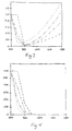
- Figure 3 shows a graph of NO x -out/NO x -in plotted against temperature for several levels of inlet O 2 concentrations.
- Figure 4 shows a graph of ammonia slip emission plotted against temperature for several levels of inlet O 2 concentrations.
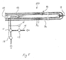
- Figure 5 shows a cross-section of the tube according to a preferred embodiment of the invention.
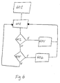
- Figure 6 shows a flow diagram for the method of controlling the temperature according to the invention.
- a combustion plant 2 comprises a combustion chamber 3 for combustion of fixed fuels having a lower grating (not shown).
- the fuel may be supplied intermittent or continuously and primary combustion air is blown in from beneath through the lower grating to the combustion chamber 3. Secondary air is supplied through supply devices, one off which is shown and denoted 1.
- the supply device has a tube 5, which is axially displaceable and enters the combustion chamber 3 through an opening in the wall of the combustion plant 2.
- Some of the particles will deposit on the inside walls, having water or steam tubing 4, as well as on the tube 5 itself. These particles may clog the orifices 5e used for inject fluids or gas and for that matter the supply device 1 is provided with cleaning means for removing flue dust from the tube 5.
- Compressed air or re-circulated flue gas is supplied to the tube 5 from a fan (not shown) via tubing 6 and flexible hose 7.
- the hose 7 comprises a quick coupling device that is connectable to a corresponding coupling device on the tube 5.
- the tube in figure 1 is disclosed in more detail.
- the tube comprises a first outer jacket 5a and an inner tube 5b. Openings or orifices 5e are distributed over the tube 5 for ejecting gas or fluids. Gas or fluids are ejected through said orifices under pressure to disturb the flue gas to create swirls or turbulence in the flue gas stream in the combustion chamber.
- Three cooling tubes are helically arranged around the inner tube 5b and fed with water through flexible hose 30.
- a further flexible hose 31 removes the used cooling water.
- Both the outer jacket 5a and the inner tube 5b have a closed inner end.
- a further hose 8 is arranged to supply ammonia aqua to the tube for ejection into the combustion chamber 3.
- ammonia injected into the combustion chamber is effectively mixed with the flue gas and will thus have an increased reactivity.
- the ammonia reacts with NO and NO 2 , commonly denoted NO x , and reduces the emission of these substances. It should be noted that even though ammonia aqua is used in this preferred embodiment ammonia in gas form may equally well be used, or even preferred.
- Figure 3 shows a graph over NO x -out/NO x -in plotted against temperature for several inlet oxygen concentrations.
- the dashed line corresponds to 0.5% O 2
- the dash-dot line corresponds to 2% O 2
- the dash-dot-dot line corresponds to 5%
- the dotted line to 10% O 2 .
- the temperature is given in degrees Celsius and as can easily be seen from the graph, the emission is at a minima around 850° to 1100° C, somewhat depending on the inlet oxygen concentration. Particularly, the emission is very low around 850° to 950° C for all oxygen concentrations.
- Figure 4 is a graph over emission of NH 3 and thus represents the slip of ammonia injected into the combustion chamber plotted against the temperature (in degrees Celsius) for several inlet oxygen concentrations.
- the level of NH 3 is given in ppm (parts per million).
- the dashed line corresponds to 0.5% O 2
- the dash-dot line corresponds to 2% O 2
- the dash-dot-dot line corresponds to 5%
- the dotted line to 10% O 2 .
- the emission of NH 3 drops sharply from 850° C and is practically insignificant for temperatures above 950° C.
- an optimal operating temperature range for introduction of ammonia into the combustion chamber is between 830° to 1100° degrees Celsius, and particularly between 850° and 950° C. It is, however, common that the temperature in the combustion chamber 3 is above this range.
- the tube 5, figure 2 has a thermocouple 9 arranged to measure the temperature in the immediate surroundings of the tube 5. If the temperature is to high, re-circulated flue gas is mixed into the secondary compressed air ejected through the orifices 5e into the combustion chamber 3. The effect of mixing air with flue gas is to reduce the amount of oxygen in the injected air thereby achieving a less violent combustion and thus a lower temperature. If, on the other hand, the temperature is to low, fuels may be added to increase the temperature.
- hydrocarbon fuels in a variety of forms may be used, that is, gaseous fuels, e.g. natural gas, fluid fuels, e.g. oil and fixed fuels, e.g. pulverized wood.
- a tube 501 is disclosed in cross-section, according to a second preferred embodiment of the invention. Like details are denoted with same numerals.
- Compressed air 10 is fed to the inner tube and is forced to exit through openings or orifices 5e.
- a hose 8 for supplying aqua ammonia to the tube 5 is coupled to a three-way valve 11. With the ejection of the compressed air into the combustion chamber swirls or turbulence is created in the flue gas stream in the combustion chamber. Thus an increased efficiency with regards to mixing the ammonia into the flue gas is achieved, thus increasing the reactivity of the ammonia with the flue gas resulting in even lower emissions of NO x .
- a first throttle valve 13 is arranged to regulate the amount of ammonia aqua supplied to the three-way valve 11 and a second throttle valve 14 controls the amount of water supplied.
- a thermocouple 9 is coupled to a processor 15, which in turn is coupled to the first and second throttle valves. The processor is arranged to control the amount of water supplied into the tube 5 through the hose 8 and also to control the amount of ammonia aqua in the water, by adjusting the first and second throttle valves 13, 14, respectively.
- the processor may determine that for example 10 kg water per minute shall be introduced into the combustion chamber 3 to reduce the temperature.
- the amount of ammonia to be injected into the combustion chamber may be set to for example 0.25 kg per minute. This equals 1 Kg per minute of 25% ammonia aqua.
- the processor thus set the first throttle valve 13 to let through 1 Kg of 25% ammonia aqua per minute and set the second throttle valve to let through approximately 9 Kg water per minute.
- the proportions is of course changed until equilibrium is achieved. If the temperature is to low a hydrocarbon fuel such as natural gas is injected.
- Figure 6 shows a flow chart according to a preferred embodiment of the invention.
- fixed parameters such as optimal operating temperature range, amount of ammonia to introduce into the combustion chamber 3 etc.
- the temperature is established 602.
- the process enters box 603 where it is established if the temperature is above the optimal operating temperature range. If so the amount of water injected into the combustion chamber 3 is increased 604. If not the process continues to box 605 where it is established if the temperature is below the optimal operating temperature range. If so natural gas is introduced into the combustion chamber 3. New reading of the temperature is then performed 602.
- the natural gas or the water may be introduced into the combustion chamber through its own tubing.
- the thermocouple may be arranged on the combustion chamber wall.
- a plant may have only means to increase the temperature in the combustion chamber 3, or alternatively only means to lower the temperature.
Landscapes
- Engineering & Computer Science (AREA)
- Mechanical Engineering (AREA)
- General Engineering & Computer Science (AREA)
- Chemical & Material Sciences (AREA)
- Combustion & Propulsion (AREA)
- Treating Waste Gases (AREA)
- Fluidized-Bed Combustion And Resonant Combustion (AREA)
Description
- The present invention relates to a method and a device for supplying at least a first fluid to a combustion chamber in a heat-generating plant, e.g. a heating boiler or a kiln. More specifically, the present invention relates to a method and a device for controlling the emissions from such a combustion chamber.
- Today a significant part of the energy generated in the modern society comes from burning of fuel. This includes wood fuels, straw, waste such as industrial, municipal, hazardous and hospital waste and also hard coal, lignite, peat, lime sludge and black liquor. These fuels are burnt in heat-generating plants in combustion chambers and results in unavoidable emission of more or less hazardous substances.
- To reduce the amount of emission different devices has been contemplated and successfully implemented in existing plants, as well as in new. In this respect reference is made to
SE9201747-4 SE9304038-4 SE9802570-3 SE0000103-2 - According to the references above reduction of emissions can be achieved by introducing secondary air into the combustion chamber in a heat-generating plant.
- Another way to achieve reduction of emission is to introduce substances, such as NH3, to reduce specific emissions, such as NO and NO2, commonly denoted NOx. The ammonia reacts with the NO and the NO2 to form substances which is not harmful to the environment.
EP 1 077 077 A2 gives an example hereof. - One problem with introducing another harmful substance, such as ammonia, is that slip can occur, i.e. ammonia is emitted to the environment.
- Another problem is that the reaction between ammonia and NOx may not always be optimal resulting in increased cost, when excessive amounts of ammonia is used to reduce the emission of NOx, but with limited success.
- Yet another problem, realized by the inventor, is that the temperature of the combustion chamber, where NH3 is introduced, is not optimal for reaction with NOx.
- It is a main object of the present invention to provide an apparatus and method for controlling the temperature in a combustion chamber to be within a preferred range, within which range a first fluid is particular active to reduce the emission of at least a first substance.
- It is in this respect a particular object of the invention to provide such apparatus and method for reducing the emission of NO and NO2.
- It is still a further object of the invention to provide such apparatus and method for effective use of supplied ammonia for reduction of emission of NO and NO2 so that no or minimal slip of ammonia emission occur.
- These objects among others are, according to a first aspect of the present invention, attained by providing a method for reducing the emissions from a combustion or gasification plant having a combustion chamber. The combustion chamber is housing means for insertion of a first fluid into said chamber, where the introduction of said fluid into said chamber is effective to reduce the emission of at least one substance. Said fluid having an optimal operating temperature range for which said fluid is particular active and thus emission is particular low. The method comprises the steps of establishing the temperature in a volume where said fluid is introduced into said combustion chamber by means of a thermocouple which is arranged on an axially displaceable tube housed in the combustion chamber. If the temperature is higher than said optimal operating range a second fluid is introduced into said chamber by means of said axially displaceable tube, where said second fluid is effective to reduce the temperature in said volume. If the temperature, on the other hand, is lower than said optimal operating temperature range a third fluid is introduced into said combustion chamber. Said third fluid is effective to increase the temperature of said volume.
- In more detail, the method according to a preferred embodiment of the present invention comprises a tube used for introducing a fourth fluid, e.g. air or re-circulated flue gas, into said chamber. The fourth fluid is inserted under pressure to create swirls or turbulence in the flue gas flow to change the flow pattern and improve mixing in the combustion chamber. Through said tube said first and second or third fluid is introduced into said chamber. Alternatively, is it also possible to use said tube for insertion of only one or two of the three fluids, and using a separate means for introduction of the remaining fluids.
- According to a first aspect of the present invention, the thermocouple is arranged on said tube for measuring the surrounding temperature where said first fluid is introduced into said chamber. Thus it is possible to continuously measure the temperature and dynamically control the introduction of said fluids into the combustion chamber to regulate the temperature.
- According to another preferred embodiment 25% ammonia aqua is mixed with water and injected into the combustion chamber through said tube. The water in the mix serves to reduce the temperature in the chamber.
The amount of water injected into the chamber is controlled to reach said optimal operating temperature range. The proportions between the ammonia aqua and the water is also controlled, in dependence of the amount of water injected, so that an optimal amount of ammonia is introduced into the chamber so as to reach a maximum reduction of the emission of NO and NO2 and also to minimize the ammonia slip. The amount of water and ammonia to be introduced into the combustion chamber varies with, for instance, the size of the combustion chamber and the temperature - These objects among others are, according to a second aspect of the present invention, attained by providing a device for reducing the emission from a combustion or gasification plant having a combustion chamber. A supplier is arranged in said chamber for supplying at least a first fluid. The fluid is effective to reduce the emission of at least one substance and has an optimal operating temperature range. The device also comprises means for controlling the temperature in at least a volume of said chamber to be in said optimal temperature range.
- According to a first preferred embodiment of the second aspect of the invention, said device comprises an axially displaceable tube for displaceable insertion into said chamber. The tube is sealed in a first end and comprises orifices along its length. The first end is inserted into said chamber. Compressed air is supplied in the second end of said tube and forced to exit the tube through said orifices creating swirls in the flue gas in the combustion chamber. Water is fed through a hose to the tube and thus made to eject, by the compressed air, through the orifices and into the combustion chamber. Ammonia aqua is mixed into said water in proportions suitable to achieve minimal or at least reduced emission of NO and NO2. The device further comprises a thermocouple, preferably arranged on said tube, coupled to control means. Said control means is arranged to increase the amount of water ejected into the chamber if the temperature is above the optimal operating range and also to control the proportion of ammonia aqua mixed into the water so that an optimal amount of ammonia is introduced into the combustion chamber.
- The device further comprises means for injecting a third fluid into said combustion chamber. The third fluid is effective to raise the temperature if the temperature is below the optimal operating temperature range. Suitably the third fluid is inserted into the chamber through the tube, but separate means is also possible to use. The third fluid can be hydrocarbon fuel in gaseous, liquid or fixed form such as natural gas, oil or pulverized wood, which will increase the combustion if introduced into a combustion chamber.
- Preferably, the water is drawn from the mains, or is wastewater or is water that has been used for cooling the tubes.
- If the object is to reduce the emission of NO and NO2, a suitable operating temperature range is 800° - 1200° C, preferably 830° - 1000° C and particularly 850° - 950° C.
- Further characteristics of the invention and advantages thereof will be evident from the following detailed description of embodiments of the invention.
- The present invention will become more fully understood from the detailed description of embodiments of the present invention given herein below and the accompanying
Figs. 1 - 6 , which are given by way of illustration only, and thus are not limitative of the present invention. -
Figure 1 is a perspective view, which shows a combustion chamber in cross-section with a tube according to a preferred embodiment of the invention. -
Figure 2 is a perspective view of the tube with parts of the tube removed. -
Figure 3 shows a graph of NOx-out/NOx-in plotted against temperature for several levels of inlet O2 concentrations. -
Figure 4 shows a graph of ammonia slip emission plotted against temperature for several levels of inlet O2 concentrations. -
Figure 5 shows a cross-section of the tube according to a preferred embodiment of the invention. -
Figure 6 shows a flow diagram for the method of controlling the temperature according to the invention. - In the following description, for purposes of explanation and not limitation, specific details are set forth, such as particular techniques and applications in order to provide a thorough understanding of the present invention. However, it will be apparent to one skilled in the art that the present invention may be practiced in other embodiments that depart from these specific details. In other instances, detailed descriptions of well-known methods and apparatuses are omitted so as not to obscure the description of the present invention with unnecessary details.
- With reference to
figure 1 , acombustion plant 2 comprises acombustion chamber 3 for combustion of fixed fuels having a lower grating (not shown). The fuel may be supplied intermittent or continuously and primary combustion air is blown in from beneath through the lower grating to thecombustion chamber 3. Secondary air is supplied through supply devices, one off which is shown and denoted 1. The supply device has atube 5, which is axially displaceable and enters thecombustion chamber 3 through an opening in the wall of thecombustion plant 2. - Some of the particles will deposit on the inside walls, having water or steam tubing 4, as well as on the
tube 5 itself. These particles may clog theorifices 5e used for inject fluids or gas and for that matter the supply device 1 is provided with cleaning means for removing flue dust from thetube 5. - Compressed air or re-circulated flue gas is supplied to the
tube 5 from a fan (not shown) viatubing 6 andflexible hose 7. Thehose 7 comprises a quick coupling device that is connectable to a corresponding coupling device on thetube 5. - With reference to
figure 2 , the tube infigure 1 is disclosed in more detail. The tube comprises a firstouter jacket 5a and aninner tube 5b. Openings ororifices 5e are distributed over thetube 5 for ejecting gas or fluids. Gas or fluids are ejected through said orifices under pressure to disturb the flue gas to create swirls or turbulence in the flue gas stream in the combustion chamber. Three cooling tubes are helically arranged around theinner tube 5b and fed with water throughflexible hose 30. A furtherflexible hose 31 removes the used cooling water. Both theouter jacket 5a and theinner tube 5b have a closed inner end. A further hose 8 is arranged to supply ammonia aqua to the tube for ejection into thecombustion chamber 3. Since the ejection of gas or fluids through theorifices 5e creates swirls in the flue gas column in the combustion chamber, the ammonia injected into the combustion chamber is effectively mixed with the flue gas and will thus have an increased reactivity. The ammonia reacts with NO and NO2, commonly denoted NOx, and reduces the emission of these substances. It should be noted that even though ammonia aqua is used in this preferred embodiment ammonia in gas form may equally well be used, or even preferred. -
Figure 3 shows a graph over NOx-out/NOx-in plotted against temperature for several inlet oxygen concentrations. The dashed line corresponds to 0.5% O2, the dash-dot line corresponds to 2% O2, the dash-dot-dot line corresponds to 5% and the dotted line to 10% O2. The temperature is given in degrees Celsius and as can easily be seen from the graph, the emission is at a minima around 850° to 1100° C, somewhat depending on the inlet oxygen concentration. Particularly, the emission is very low around 850° to 950° C for all oxygen concentrations. -
Figure 4 is a graph over emission of NH3 and thus represents the slip of ammonia injected into the combustion chamber plotted against the temperature (in degrees Celsius) for several inlet oxygen concentrations. The level of NH3 is given in ppm (parts per million). The dashed line corresponds to 0.5% O2, the dash-dot line corresponds to 2% O2, the dash-dot-dot line corresponds to 5% and the dotted line to 10% O2. As can be seen from the graph the emission of NH3 drops sharply from 850° C and is practically insignificant for temperatures above 950° C. - It is clear from
figures 3 and 4 that an optimal operating temperature range for introduction of ammonia into the combustion chamber is between 830° to 1100° degrees Celsius, and particularly between 850° and 950° C. It is, however, common that the temperature in thecombustion chamber 3 is above this range. - In this respect the
tube 5,figure 2 , has athermocouple 9 arranged to measure the temperature in the immediate surroundings of thetube 5. If the temperature is to high, re-circulated flue gas is mixed into the secondary compressed air ejected through theorifices 5e into thecombustion chamber 3. The effect of mixing air with flue gas is to reduce the amount of oxygen in the injected air thereby achieving a less violent combustion and thus a lower temperature. If, on the other hand, the temperature is to low, fuels may be added to increase the temperature. In this respect hydrocarbon fuels in a variety of forms may be used, that is, gaseous fuels, e.g. natural gas, fluid fuels, e.g. oil and fixed fuels, e.g. pulverized wood. - With reference to
figure 5 , atube 501 is disclosed in cross-section, according to a second preferred embodiment of the invention. Like details are denoted with same numerals.Compressed air 10 is fed to the inner tube and is forced to exit through openings ororifices 5e. A hose 8 for supplying aqua ammonia to thetube 5 is coupled to a three-way valve 11. With the ejection of the compressed air into the combustion chamber swirls or turbulence is created in the flue gas stream in the combustion chamber. Thus an increased efficiency with regards to mixing the ammonia into the flue gas is achieved, thus increasing the reactivity of the ammonia with the flue gas resulting in even lower emissions of NOx. To the three-way valve 11 is also fed 25% ammonia aqua through ahose 12. Afirst throttle valve 13 is arranged to regulate the amount of ammonia aqua supplied to the three-way valve 11 and asecond throttle valve 14 controls the amount of water supplied. Athermocouple 9 is coupled to aprocessor 15, which in turn is coupled to the first and second throttle valves. The processor is arranged to control the amount of water supplied into thetube 5 through the hose 8 and also to control the amount of ammonia aqua in the water, by adjusting the first andsecond throttle valves - For example, if the processor records that the temperature is 1000° C and the upper limit value for the optimal operating temperature range is 950°, the processor may determine that for example 10 kg water per minute shall be introduced into the
combustion chamber 3 to reduce the temperature. The amount of ammonia to be injected into the combustion chamber may be set to for example 0.25 kg per minute. This equals 1 Kg per minute of 25% ammonia aqua. The processor thus set thefirst throttle valve 13 to let through 1 Kg of 25% ammonia aqua per minute and set the second throttle valve to let through approximately 9 Kg water per minute. When the temperature drops, the proportions is of course changed until equilibrium is achieved. If the temperature is to low a hydrocarbon fuel such as natural gas is injected. -
Figure 6 shows a flow chart according to a preferred embodiment of the invention. Initially, inbox 601, fixed parameters are set, such as optimal operating temperature range, amount of ammonia to introduce into thecombustion chamber 3 etc. The temperature is established 602. Then the process entersbox 603 where it is established if the temperature is above the optimal operating temperature range. If so the amount of water injected into thecombustion chamber 3 is increased 604. If not the process continues to box 605 where it is established if the temperature is below the optimal operating temperature range. If so natural gas is introduced into thecombustion chamber 3. New reading of the temperature is then performed 602. - It will be obvious that the invention may be varied in a plurality of ways. The natural gas or the water may be introduced into the combustion chamber through its own tubing. The thermocouple may be arranged on the combustion chamber wall. A plant may have only means to increase the temperature in the
combustion chamber 3, or alternatively only means to lower the temperature. - Even though only emissions of NOx has been discussed in the foregoing, other types of emissions can be lowered using the same methods and devices, however with use of other fluids. For instance, injecting limestone or bicarbonate into the combustion chamber may reduce emissions of SOx, hydrochloric acid, heavy metals and dioxin. These processes will also have optimal operating temperature ranges and would thus be well suited to use with the inventive devices and methods. It is thus clear that the present invention is not limited to reducing emission of a particular substance, but indeed would be suitable for optimizing several different emissions characteristics.
- Such variations are not to be regarded as a departure from the scope of the invention. All such modifications as would be obvious to one skilled in the art are intended to be included within the scope of the appended claims.
Claims (21)
- A method for reducing emissions from a combustion or gasification plant, said plant having a combustion chamber housing means for insertion of a first fluid into said chamber, introduction of said first fluid into said chamber being effective to reduce the emission of at least one substance from said combustion and said first fluid having an optimal operating temperature range for which emissions are particularly low, characterised in that said method comprises the steps of,- establishing the temperature in a volume in said combustion chamber by means of a thermocouple which is arranged on an axially displaceable tube housed in the combustion chamber, where said volume includes the position for insertion of said first fluid,- inserting into said combustion chamber, by means of said axially displaceable tube, a second fluid effective to reduce the temperature in said volume in said combustion chamber, if said temperature is established to be higher than said optimal temperature range, and- inserting into said combustion chamber a third fluid effective to increase the temperature in said volume in said combustion chamber, if said temperature is established to be lower than said optimal temperature range.
- The method according to claim 1, wherein a fourth fluid is inserted under pressure through said axially displaceable tube into said combustions chamber so as to disturb the flow of flue gas in said combustion chamber to create swirls, change the flow pattern and improve the mixing in said combustion chamber.
- The method according to claim 2, wherein said fourth fluid is air or re-circulated flue gas.
- The method according to claim 1, wherein said second fluid is introduced under pressure through said axially displaceable tube so as to disturb the flow of flue gas in said combustion chamber to create swirls, change the flow pattern and improve the mixing in said combustion chamber.
- The method according to any of claims 1 to 4, wherein said temperature is continuously established and the amount of said second and/or third fluid is continuously controlled to achieve said optimal temperature range.
- The method according to claim 1, wherein said first fluid is selected from a group of fluids including NOx reducing agents, such as ammonia aqua, ammonia gas, urea and SOx or HCl reducing agents, such as lime stone and bicarbonate.
- The method according to claim 1, wherein said first fluid is ammonia aqua or ammonia gas, said second fluid is water and said third fluid is selected from a group of fuels of hydrocarbons including gaseous fuels, e.g. natural gas, liquid fuels, e.g. oil and solid fuels, e.g. pulverized wood.
- The method according to claim 7, wherein- said ammonia aqua and said water is mixed, and- the proportion of NH3 in the water is controlled to supply an optimal volume part of NH3 to reduce the emissions of NOx to a maximum extent, and an optimal volume part of water to reduce the temperature in the combustion chamber to the optimal temperature range.
- A combustion or gasification plant comprising a device for reducing the emission of at least one substance from said combustion or gasification plant by means of supplying a first fluid for optimising flue gas or gas parameters, said first fluid being effective to reduce the emission of said at least one substance and having a optimal operating temperature range,- said plant comprising a combustion or gasification chamber having a supplier for supplying at least said first fluid to said chamber, characterised in,- an axially displaceable tube housed in the combustion chamber,- which tube is equipped with a thermocouple for controlling the temperature in said combustion chamber, in at least a volume comprising the position of insertion of said first fluid into said chamber, to be in said optimal operating temperature range and- which tube is arranged to supply a second fluid effective to reduce the temperature in said volume in said combustion chamber, if said temperature is established to be higher than said optimal temperature range.
- The plant according to claim 9, wherein said supplier is at least one axially displaceable tube for displaceable insertion into said combustion chamber.
- The plant according to claim 9 or 10, wherein said second fluid is introduced under pressure into said combustion chamber so as to disturb the flow of flue gas in the combustion chamber to create swirls, change the flow pattern and improve the mixing in said combustion chamber.
- The plant according to any of the claims 9-11, wherein said first fluid is selected from a group of fluids including NOx reducing agents, such as ammonia aqua, ammonia gas, urea and SOx or HCl reducing agents, such as lime stone and bicarbonate.
- The plant according to claim 12, wherein said first fluid is ammonia aqua or ammonia gas and said tube comprises means for supplying compressed air into a cavity of said tube, means for supplying water into said cavity and that said tube comprises orifices through which said water and compressed air ejects into said combustion chamber to lower the temperature in said volume if said temperature is above said optimal operating temperature range and to disturb the flow of the flue gas in said combustion chamber to create swirls, change the flow pattern and improve the mixing in said combustion chamber.
- The plant according to any of claims 9-12, wherein said second fluid is flue gas.
- The plant according to claim 13, wherein said water supplying means comprises a first controller for controlling the amount of water supplied to said chamber, a mixer for mixing ammonia aqua into said water, a second controller for controlling the amount of ammonia aqua mixed into said water, and wherein said thermocouple is coupled to said first and second controller for controlling the amount of water and NH3 supplied to the combustion chamber.
- The plant according to claim 13, wherein said first and second controller is throttle valves, said mixer is a three-way valve, and wherein said thermocouple is coupled to a computer arranged to control said valves.
- The plant according to any of claims 13, wherein said water is supplied from a group of sources including: the water mains, the drain or cooling water from the cooling of said tube.
- The plant according to any of claims 9 to 17, wherein said device further comprises means for ejecting a third fluid into said combustion chamber, said fluid being effective to raise the temperature in said volume in said combustion chamber if said temperature is below said optimal operating range.
- The plant according to claim 18, wherein said third fluid is ejected through said tube, and said third fluid is selected from a group of fuels of hydrocarbons including gaseous fuels, e.g. natural gas, liquid fuels, e.g. oil and solid fuels, e.g. pulverized wood.
- The plant according to any of claims 9-19, wherein said device comprises means for ejecting a fourth fluid into said combustion chamber through said tube under pressure so as to disturb the flow of the flue gas in the combustion chamber to create swirls, change the flow pattern and improve the mixing in said combustion chamber.
- The plant according to claim 20, wherein said fourth fluid is air or re-circulated flue gas.
Applications Claiming Priority (2)
| Application Number | Priority Date | Filing Date | Title |
|---|---|---|---|
| SE0103822A SE0103822D0 (en) | 2001-11-16 | 2001-11-16 | Combustion optimization |
| SE0103822 | 2001-11-16 |
Publications (3)
| Publication Number | Publication Date |
|---|---|
| EP1312862A2 EP1312862A2 (en) | 2003-05-21 |
| EP1312862A3 EP1312862A3 (en) | 2004-09-08 |
| EP1312862B1 true EP1312862B1 (en) | 2014-02-26 |
Family
ID=20286009
Family Applications (1)
| Application Number | Title | Priority Date | Filing Date |
|---|---|---|---|
| EP02445151.0A Expired - Lifetime EP1312862B1 (en) | 2001-11-16 | 2002-11-15 | Combustion optimization |
Country Status (4)
| Country | Link |
|---|---|
| US (1) | US6712606B2 (en) |
| EP (1) | EP1312862B1 (en) |
| DK (1) | DK1312862T3 (en) |
| SE (1) | SE0103822D0 (en) |
Families Citing this family (20)
| Publication number | Priority date | Publication date | Assignee | Title |
|---|---|---|---|---|
| US20100139155A1 (en) * | 2009-01-26 | 2010-06-10 | Mennell James A | Switch grass fuel objects with high heat output and reduced air emissions designed for large-scale power generation |
| US20100139156A1 (en) * | 2009-01-26 | 2010-06-10 | Mennell James A | Corn stover fuel objects with high heat output and reduced emissions designed for large-scale power generation |
| FR2941869B1 (en) * | 2009-02-10 | 2013-03-29 | Novergie | PROCESS FOR REDUCING NITROGEN OXIDES FROM COMBUSTION OF SOLID FUELS |
| US9388046B2 (en) | 2011-04-15 | 2016-07-12 | Biogenic Reagents Ventures, Llc | Systems and apparatus for production of high-carbon biogenic reagents |
| EP2766684A1 (en) * | 2011-10-12 | 2014-08-20 | Ecomb AB (publ) | Cooling of combustion chamber supply device |
| EP2847127B1 (en) | 2012-05-07 | 2020-10-14 | Carbon Technology Holdings, LLC | Continuous process for producing biogenic activated carbon |
| US12350648B2 (en) | 2013-10-24 | 2025-07-08 | Carbon Technology Holdings, LLC | Methods and apparatus for producing activated carbon from biomass through carbonized ash intermediates |
| MX2016009270A (en) | 2014-01-16 | 2017-05-04 | Biogenic Reagents Ventures Llc | CARBON MICROPLANTA. |
| WO2015127460A1 (en) | 2014-02-24 | 2015-08-27 | Biogenic Reagent Ventures, Llc | Highly mesoporous activated carbon |
| WO2016065357A1 (en) | 2014-10-24 | 2016-04-28 | Biogenic Reagent Ventures, Llc | Halogenated activated carbon compositions and methods of making and using same |
| EP3047896B1 (en) * | 2015-01-20 | 2017-09-06 | General Electric Technology GmbH | Boiler and device for selective non catalytic reduction |
| EP3806997A4 (en) | 2018-06-14 | 2022-03-09 | Carbon Technology Holdings, LLC | BIOGENIC POROUS CARBON SILICON DIOXIDE COMPOSITIONS AND PROCESSES FOR THEIR PREPARATION AND USE |
| CA3195363A1 (en) | 2020-09-25 | 2022-03-31 | Carbon Technology Holdings, LLC | Bio-reduction of metal ores integrated with biomass pyrolysis |
| AU2022221681A1 (en) | 2021-02-18 | 2023-10-05 | Carbon Technology Holdings, LLC | Carbon-negative metallurgical products |
| CN112984515B (en) * | 2021-03-29 | 2021-10-19 | 航天神禾(北京)环保有限公司 | Multistage atomizing spray gun, quench tower and waste salt recycling system |
| US11932814B2 (en) | 2021-04-27 | 2024-03-19 | Carbon Technology Holdings, LLC | Biocarbon blends with optimized fixed carbon content, and methods for making and using the same |
| KR20240034210A (en) | 2021-07-09 | 2024-03-13 | 카본 테크놀로지 홀딩스, 엘엘씨 | Process for producing biocarbon pellets with high fixed-carbon content and optimized reactivity, and biocarbon pellets obtained therefrom |
| AU2022323092A1 (en) | 2021-08-02 | 2024-03-21 | Carbon Technology Holdings, LLC | Processes and systems for recapturing carbon from biomass pyrolysis liquids |
| EP4430018A4 (en) | 2021-11-12 | 2026-02-11 | Carbon Tech Holdings Llc | Biocarbon compositions with optimized composition parameters and methods for their production |
| CN117076834B (en) * | 2023-09-01 | 2024-04-19 | 北京启迪中谷能源科技有限公司 | Biomass low-nitridation combustion adjusting method and system |
Family Cites Families (19)
| Publication number | Priority date | Publication date | Assignee | Title |
|---|---|---|---|---|
| JPS5623615A (en) * | 1979-08-06 | 1981-03-06 | Babcock Hitachi Kk | Burning method for low nox |
| JPH0799257B2 (en) * | 1986-01-21 | 1995-10-25 | 石川島播磨重工業株式会社 | Stable combustion method of fluidized bed furnace |
| US5269235A (en) * | 1988-10-03 | 1993-12-14 | Koch Engineering Company, Inc. | Three stage combustion apparatus |
| DE3907330A1 (en) | 1989-03-04 | 1990-09-13 | Noell Gmbh | Separation process |
| US5252298A (en) | 1991-04-23 | 1993-10-12 | Noell, Inc. | Device for cleaning gases |
| SE501418C2 (en) * | 1992-05-18 | 1995-02-13 | Gothia Tool Trading Hb | Process and device at combustion unit to create conditions for reduction of environmentally harmful substances |
| SE502188C2 (en) * | 1992-06-05 | 1995-09-11 | Ulf Hagstroem | Methods and apparatus for avoiding disturbances caused by coatings on feeders for combustion or gasification plants |
| US5286458A (en) | 1992-12-22 | 1994-02-15 | Industrial Technology Research Institute | Injection type non-catalyst denitrogen oxide process control system |
| US5326536A (en) * | 1993-04-30 | 1994-07-05 | The Babcock & Wilcox Company | Apparatus for injecting NOx inhibiting liquid reagent into the flue gas of a boiler in response to a sensed temperature |
| SE502283C2 (en) * | 1993-12-03 | 1995-09-25 | Ulf Hagstroem | Methods and supply means for regulating mixing conditions in a combustion or gasification plant |
| KR100474034B1 (en) * | 1995-05-17 | 2005-06-20 | 히타치 조센 가부시키가이샤 | Waste Incineration Method and Equipment |
| IT1276701B1 (en) * | 1995-06-12 | 1997-11-03 | Finmeccanica Spa | WASTE INCINERATION PLANT WITH HOT DUSTERISATION OF THE FUME AND HOT REDUCTION OF THE ACID SUBSTANCES OF THE FUME, IN |
| US5707596A (en) * | 1995-11-08 | 1998-01-13 | Process Combustion Corporation | Method to minimize chemically bound nox in a combustion process |
| US5738024A (en) * | 1996-04-19 | 1998-04-14 | Winegar; Phillip | Catalytic reduction apparatus for NOX reduction |
| US5908003A (en) * | 1996-08-15 | 1999-06-01 | Gas Research Institute | Nitrogen oxide reduction by gaseous fuel injection in low temperature, overall fuel-lean flue gas |
| SE512517C2 (en) | 1998-07-17 | 2000-03-27 | Ecomb Ab | Supply fluid for a combustion chamber fluid |
| DE19938269A1 (en) * | 1999-08-12 | 2001-02-15 | Asea Brown Boveri | Process for the thermal treatment of solids |
| US6206685B1 (en) * | 1999-08-31 | 2001-03-27 | Ge Energy And Environmental Research Corporation | Method for reducing NOx in combustion flue gas using metal-containing additives |
| SE515645C2 (en) | 2000-01-14 | 2001-09-17 | Ecomb Ab | Camera-supplied supply fluid for a combustion chamber |
-
2001
- 2001-11-16 SE SE0103822A patent/SE0103822D0/en unknown
-
2002
- 2002-11-15 EP EP02445151.0A patent/EP1312862B1/en not_active Expired - Lifetime
- 2002-11-15 US US10/294,940 patent/US6712606B2/en not_active Expired - Lifetime
- 2002-11-15 DK DK02445151.0T patent/DK1312862T3/en active
Also Published As
| Publication number | Publication date |
|---|---|
| EP1312862A2 (en) | 2003-05-21 |
| US20030124477A1 (en) | 2003-07-03 |
| DK1312862T3 (en) | 2014-05-26 |
| US6712606B2 (en) | 2004-03-30 |
| SE0103822D0 (en) | 2001-11-16 |
| EP1312862A3 (en) | 2004-09-08 |
Similar Documents
| Publication | Publication Date | Title |
|---|---|---|
| US6712606B2 (en) | Combustion optimization | |
| US5632211A (en) | Method and apparatus for waste incineration | |
| CA2590921C (en) | Method for supplying combustion gas in incineration systems | |
| JP5996147B2 (en) | Extension or multiple reaction parts in the cleaning device | |
| US8375872B2 (en) | Process for reduction of sulfur compounds and nitrogen compounds in the exhaust gases of combustion devices | |
| JP3329815B2 (en) | Feeding means for a combustion gasification plant and a method for minimizing inhibitory deposits deposited on such means | |
| CA2088659C (en) | Apparatus and process for control of nitric oxide emissions from combustion devices using vortex rings and the like | |
| US5213492A (en) | Combustion method for simultaneous control of nitrogen oxides and products of incomplete combustion | |
| CN101674874B (en) | Tertiary addition of air to solid waste burner for NOX control | |
| KR20250141795A (en) | Combustion system and boiler system and method of operating combustion system | |
| US4981660A (en) | Selective hybrid NOx reduction process | |
| JP2561978Y2 (en) | Garbage incinerator | |
| US5242295A (en) | Combustion method for simultaneous control of nitrogen oxides and products of incomplete combustion | |
| JP2002174404A (en) | Fluidized bed incinerator | |
| EP0730718B1 (en) | A method and a feeding apparatus for controlling mixing conditions in a combustion or gasification plant | |
| CA2060953C (en) | Combustion method for simultaneous control of nitrogen oxides and products of incomplete combustion | |
| KR100689106B1 (en) | Apparatus and Method for Reducing Nitrogen Oxide in Fluidized Bed Combustor | |
| US20070193476A1 (en) | Fly ash beneficiation systems with sulfur removal and methods thereof | |
| JP3681130B2 (en) | Denitration apparatus and method in cement plant | |
| JP3771791B2 (en) | Waste incinerator with high water content and high volatility such as sewage sludge | |
| US8075858B1 (en) | Trumpet shaped element and process for minimizing solid and gaseous pollutants from waste off-gasses and liquid streams | |
| KR101910122B1 (en) | Low nitrogen monoxide scrubber and method for reducing nitrogen monoxide using the same | |
| CN223622923U (en) | Sludge treatment equipment | |
| KR102419214B1 (en) | Waste incineration system | |
| KR100375523B1 (en) | Waste gas purification device for condensing boiler |
Legal Events
| Date | Code | Title | Description |
|---|---|---|---|
| PUAI | Public reference made under article 153(3) epc to a published international application that has entered the european phase |
Free format text: ORIGINAL CODE: 0009012 |
|
| AK | Designated contracting states |
Designated state(s): AT BE BG CH CY CZ DE DK EE ES FI FR GB GR IE IT LI LU MC NL PT SE SK TR |
|
| AX | Request for extension of the european patent |
Extension state: AL LT LV MK RO SI |
|
| PUAL | Search report despatched |
Free format text: ORIGINAL CODE: 0009013 |
|
| AK | Designated contracting states |
Kind code of ref document: A3 Designated state(s): AT BE BG CH CY CZ DE DK EE ES FI FR GB GR IE IT LI LU MC NL PT SE SK TR |
|
| AX | Request for extension of the european patent |
Extension state: AL LT LV MK RO SI |
|
| RIC1 | Information provided on ipc code assigned before grant |
Ipc: 7F 23C 9/08 B Ipc: 7F 23L 9/02 B Ipc: 7F 23G 5/50 B Ipc: 7F 23L 7/00 B Ipc: 7F 23J 7/00 A |
|
| 17P | Request for examination filed |
Effective date: 20050228 |
|
| AKX | Designation fees paid |
Designated state(s): AT BE BG CH CY CZ DE DK EE ES FI FR GB GR IE IT LI LU MC NL PT SE SK TR |
|
| 17Q | First examination report despatched |
Effective date: 20090423 |
|
| GRAP | Despatch of communication of intention to grant a patent |
Free format text: ORIGINAL CODE: EPIDOSNIGR1 |
|
| INTG | Intention to grant announced |
Effective date: 20130909 |
|
| GRAS | Grant fee paid |
Free format text: ORIGINAL CODE: EPIDOSNIGR3 |
|
| GRAA | (expected) grant |
Free format text: ORIGINAL CODE: 0009210 |
|
| AK | Designated contracting states |
Kind code of ref document: B1 Designated state(s): AT BE BG CH CY CZ DE DK EE ES FI FR GB GR IE IT LI LU MC NL PT SE SK TR |
|
| REG | Reference to a national code |
Ref country code: GB Ref legal event code: FG4D |
|
| REG | Reference to a national code |
Ref country code: CH Ref legal event code: EP |
|
| REG | Reference to a national code |
Ref country code: AT Ref legal event code: REF Ref document number: 653837 Country of ref document: AT Kind code of ref document: T Effective date: 20140315 |
|
| REG | Reference to a national code |
Ref country code: IE Ref legal event code: FG4D |
|
| REG | Reference to a national code |
Ref country code: DE Ref legal event code: R096 Ref document number: 60246013 Country of ref document: DE Effective date: 20140410 |
|
| REG | Reference to a national code |
Ref country code: NL Ref legal event code: T3 |
|
| REG | Reference to a national code |
Ref country code: DK Ref legal event code: T3 Effective date: 20140522 |
|
| REG | Reference to a national code |
Ref country code: SE Ref legal event code: TRGR |
|
| REG | Reference to a national code |
Ref country code: AT Ref legal event code: MK05 Ref document number: 653837 Country of ref document: AT Kind code of ref document: T Effective date: 20140226 |
|
| PG25 | Lapsed in a contracting state [announced via postgrant information from national office to epo] |
Ref country code: AT Free format text: LAPSE BECAUSE OF FAILURE TO SUBMIT A TRANSLATION OF THE DESCRIPTION OR TO PAY THE FEE WITHIN THE PRESCRIBED TIME-LIMIT Effective date: 20140226 Ref country code: CY Free format text: LAPSE BECAUSE OF FAILURE TO SUBMIT A TRANSLATION OF THE DESCRIPTION OR TO PAY THE FEE WITHIN THE PRESCRIBED TIME-LIMIT Effective date: 20140226 Ref country code: PT Free format text: LAPSE BECAUSE OF FAILURE TO SUBMIT A TRANSLATION OF THE DESCRIPTION OR TO PAY THE FEE WITHIN THE PRESCRIBED TIME-LIMIT Effective date: 20140626 |
|
| PG25 | Lapsed in a contracting state [announced via postgrant information from national office to epo] |
Ref country code: BE Free format text: LAPSE BECAUSE OF FAILURE TO SUBMIT A TRANSLATION OF THE DESCRIPTION OR TO PAY THE FEE WITHIN THE PRESCRIBED TIME-LIMIT Effective date: 20140226 |
|
| PG25 | Lapsed in a contracting state [announced via postgrant information from national office to epo] |
Ref country code: CZ Free format text: LAPSE BECAUSE OF FAILURE TO SUBMIT A TRANSLATION OF THE DESCRIPTION OR TO PAY THE FEE WITHIN THE PRESCRIBED TIME-LIMIT Effective date: 20140226 Ref country code: EE Free format text: LAPSE BECAUSE OF FAILURE TO SUBMIT A TRANSLATION OF THE DESCRIPTION OR TO PAY THE FEE WITHIN THE PRESCRIBED TIME-LIMIT Effective date: 20140226 |
|
| REG | Reference to a national code |
Ref country code: DE Ref legal event code: R097 Ref document number: 60246013 Country of ref document: DE |
|
| PG25 | Lapsed in a contracting state [announced via postgrant information from national office to epo] |
Ref country code: ES Free format text: LAPSE BECAUSE OF FAILURE TO SUBMIT A TRANSLATION OF THE DESCRIPTION OR TO PAY THE FEE WITHIN THE PRESCRIBED TIME-LIMIT Effective date: 20140226 Ref country code: SK Free format text: LAPSE BECAUSE OF FAILURE TO SUBMIT A TRANSLATION OF THE DESCRIPTION OR TO PAY THE FEE WITHIN THE PRESCRIBED TIME-LIMIT Effective date: 20140226 |
|
| PLBE | No opposition filed within time limit |
Free format text: ORIGINAL CODE: 0009261 |
|
| STAA | Information on the status of an ep patent application or granted ep patent |
Free format text: STATUS: NO OPPOSITION FILED WITHIN TIME LIMIT |
|
| PGFP | Annual fee paid to national office [announced via postgrant information from national office to epo] |
Ref country code: DE Payment date: 20141119 Year of fee payment: 13 |
|
| 26N | No opposition filed |
Effective date: 20141127 |
|
| PGFP | Annual fee paid to national office [announced via postgrant information from national office to epo] |
Ref country code: NL Payment date: 20141118 Year of fee payment: 13 |
|
| REG | Reference to a national code |
Ref country code: DE Ref legal event code: R097 Ref document number: 60246013 Country of ref document: DE Effective date: 20141127 |
|
| PG25 | Lapsed in a contracting state [announced via postgrant information from national office to epo] |
Ref country code: IT Free format text: LAPSE BECAUSE OF FAILURE TO SUBMIT A TRANSLATION OF THE DESCRIPTION OR TO PAY THE FEE WITHIN THE PRESCRIBED TIME-LIMIT Effective date: 20140226 |
|
| PG25 | Lapsed in a contracting state [announced via postgrant information from national office to epo] |
Ref country code: MC Free format text: LAPSE BECAUSE OF FAILURE TO SUBMIT A TRANSLATION OF THE DESCRIPTION OR TO PAY THE FEE WITHIN THE PRESCRIBED TIME-LIMIT Effective date: 20140226 Ref country code: LU Free format text: LAPSE BECAUSE OF FAILURE TO SUBMIT A TRANSLATION OF THE DESCRIPTION OR TO PAY THE FEE WITHIN THE PRESCRIBED TIME-LIMIT Effective date: 20141115 |
|
| REG | Reference to a national code |
Ref country code: CH Ref legal event code: PL |
|
| PG25 | Lapsed in a contracting state [announced via postgrant information from national office to epo] |
Ref country code: LI Free format text: LAPSE BECAUSE OF NON-PAYMENT OF DUE FEES Effective date: 20141130 Ref country code: CH Free format text: LAPSE BECAUSE OF NON-PAYMENT OF DUE FEES Effective date: 20141130 |
|
| REG | Reference to a national code |
Ref country code: FR Ref legal event code: PLFP Year of fee payment: 14 |
|
| PG25 | Lapsed in a contracting state [announced via postgrant information from national office to epo] |
Ref country code: BG Free format text: LAPSE BECAUSE OF FAILURE TO SUBMIT A TRANSLATION OF THE DESCRIPTION OR TO PAY THE FEE WITHIN THE PRESCRIBED TIME-LIMIT Effective date: 20140226 |
|
| REG | Reference to a national code |
Ref country code: DE Ref legal event code: R119 Ref document number: 60246013 Country of ref document: DE |
|
| PG25 | Lapsed in a contracting state [announced via postgrant information from national office to epo] |
Ref country code: GR Free format text: LAPSE BECAUSE OF FAILURE TO SUBMIT A TRANSLATION OF THE DESCRIPTION OR TO PAY THE FEE WITHIN THE PRESCRIBED TIME-LIMIT Effective date: 20140527 |
|
| PG25 | Lapsed in a contracting state [announced via postgrant information from national office to epo] |
Ref country code: TR Free format text: LAPSE BECAUSE OF FAILURE TO SUBMIT A TRANSLATION OF THE DESCRIPTION OR TO PAY THE FEE WITHIN THE PRESCRIBED TIME-LIMIT Effective date: 20140226 |
|
| REG | Reference to a national code |
Ref country code: NL Ref legal event code: MM Effective date: 20151201 |
|
| PG25 | Lapsed in a contracting state [announced via postgrant information from national office to epo] |
Ref country code: NL Free format text: LAPSE BECAUSE OF NON-PAYMENT OF DUE FEES Effective date: 20151201 |
|
| PG25 | Lapsed in a contracting state [announced via postgrant information from national office to epo] |
Ref country code: DE Free format text: LAPSE BECAUSE OF NON-PAYMENT OF DUE FEES Effective date: 20160601 |
|
| REG | Reference to a national code |
Ref country code: FR Ref legal event code: PLFP Year of fee payment: 15 |
|
| REG | Reference to a national code |
Ref country code: FR Ref legal event code: PLFP Year of fee payment: 16 |
|
| PGFP | Annual fee paid to national office [announced via postgrant information from national office to epo] |
Ref country code: DK Payment date: 20171115 Year of fee payment: 16 |
|
| PGFP | Annual fee paid to national office [announced via postgrant information from national office to epo] |
Ref country code: IE Payment date: 20181112 Year of fee payment: 17 Ref country code: FI Payment date: 20181130 Year of fee payment: 17 Ref country code: SE Payment date: 20181130 Year of fee payment: 17 |
|
| PGFP | Annual fee paid to national office [announced via postgrant information from national office to epo] |
Ref country code: FR Payment date: 20181130 Year of fee payment: 17 Ref country code: GB Payment date: 20181130 Year of fee payment: 17 |
|
| REG | Reference to a national code |
Ref country code: DK Ref legal event code: EBP Effective date: 20181130 |
|
| PG25 | Lapsed in a contracting state [announced via postgrant information from national office to epo] |
Ref country code: DK Free format text: LAPSE BECAUSE OF NON-PAYMENT OF DUE FEES Effective date: 20181130 |
|
| REG | Reference to a national code |
Ref country code: FI Ref legal event code: MAE |
|
| REG | Reference to a national code |
Ref country code: SE Ref legal event code: EUG |
|
| PG25 | Lapsed in a contracting state [announced via postgrant information from national office to epo] |
Ref country code: FI Free format text: LAPSE BECAUSE OF NON-PAYMENT OF DUE FEES Effective date: 20191115 |
|
| PG25 | Lapsed in a contracting state [announced via postgrant information from national office to epo] |
Ref country code: SE Free format text: LAPSE BECAUSE OF NON-PAYMENT OF DUE FEES Effective date: 20191116 |
|
| GBPC | Gb: european patent ceased through non-payment of renewal fee |
Effective date: 20191115 |
|
| PG25 | Lapsed in a contracting state [announced via postgrant information from national office to epo] |
Ref country code: IE Free format text: LAPSE BECAUSE OF NON-PAYMENT OF DUE FEES Effective date: 20191115 Ref country code: GB Free format text: LAPSE BECAUSE OF NON-PAYMENT OF DUE FEES Effective date: 20191115 |
|
| PG25 | Lapsed in a contracting state [announced via postgrant information from national office to epo] |
Ref country code: FR Free format text: LAPSE BECAUSE OF NON-PAYMENT OF DUE FEES Effective date: 20191202 |