EP1312544A2 - Scooter type motorcycle - Google Patents
Scooter type motorcycle Download PDFInfo
- Publication number
- EP1312544A2 EP1312544A2 EP02025729A EP02025729A EP1312544A2 EP 1312544 A2 EP1312544 A2 EP 1312544A2 EP 02025729 A EP02025729 A EP 02025729A EP 02025729 A EP02025729 A EP 02025729A EP 1312544 A2 EP1312544 A2 EP 1312544A2
- Authority
- EP
- European Patent Office
- Prior art keywords
- rear wheel
- wheel
- scooter type
- drive shaft
- type motorcycle
- Prior art date
- Legal status (The legal status is an assumption and is not a legal conclusion. Google has not performed a legal analysis and makes no representation as to the accuracy of the status listed.)
- Withdrawn
Links
- 230000002093 peripheral effect Effects 0.000 claims description 5
- 230000005540 biological transmission Effects 0.000 abstract description 17
- 230000008878 coupling Effects 0.000 description 4
- 238000010168 coupling process Methods 0.000 description 4
- 238000005859 coupling reaction Methods 0.000 description 4
- 230000001737 promoting effect Effects 0.000 description 2
- 230000000694 effects Effects 0.000 description 1
- 230000005489 elastic deformation Effects 0.000 description 1
- 239000011295 pitch Substances 0.000 description 1
Images


Classifications
-
- B—PERFORMING OPERATIONS; TRANSPORTING
- B62—LAND VEHICLES FOR TRAVELLING OTHERWISE THAN ON RAILS
- B62M—RIDER PROPULSION OF WHEELED VEHICLES OR SLEDGES; POWERED PROPULSION OF SLEDGES OR SINGLE-TRACK CYCLES; TRANSMISSIONS SPECIALLY ADAPTED FOR SUCH VEHICLES
- B62M21/00—Transmissions characterised by use of resilient elements therein
Definitions
- the present invention relates to a scooter type motorcycle having a unit swing type engine driving a rear wheel via a drive shaft extending in a vehicle width direction.
- a unit swing type engine mounted to a scooter type motorcycle is constituted by integrating the engine and a transmission mechanism of an automatic transmission, a speed reduction gear or the like and supported by a rear portion of a vehicle body pivotably in an up and down direction and a drive shaft (output shaft)extended from the rear portion in a vehicle width direction is directly coupled with a rear wheel by a serration coupling.
- rotation of the engine is transmitted to the drive shaft via the transmission mechanism of the automatic transmission or the speed reduction gear and is transmitted from the drive shaft directly to the rear wheel.
- the ride comfort characteristic is promoted by absorbing the variation in the torque of the engine by a wheel damper, it is spatially difficult to integrate the wheel damper to the scooter type motorcycle.
- a scooter type motorcycle having a unit swing type engine driving a rear wheel via a drive shaft extending in a vehicle width direction, wherein the wheel damper is integrated within the width of the rear wheel.
- the wheel damper is arranged within the width of the rear wheel, any spatial difficulty can be avoided and the ride comfort can be distinctively improved.
- a scooter type motorcycle constituted by supporting a rear wheel by a drive shaft extended from a unit swing type engine in a vehicle width direction has a wheel portion structure comprising:
- a rib for a wheel damper is formed at a vicinity of a vehicle body center of the rear wheel and a parking brake is arranged at a vicinity of the rib for the wheel damper of the rear wheel.
- the boss portion of the clutch member and the boss portion of the rear wheel are fitted to each other at the same position as the position of the power transmission portion of the rear wheel in the width direction and therefore, the wheel damper preferably constituted by the clutch member, the power transmitting portion of the rear wheel, the elastic member and the like is integrated within the width of the rear wheel, rational arrangement of the wheel damper can be carried out without being accompanied by spatial difficulty and the torque variation of the engine is absorbed by the wheel damper to thereby promote the ride comfort characteristic of the scooter type motorcycle.
- the wheel damper and the parking brake are arranged to the wheel to be contiguous to each other, the wheel is reinforced by the rib for the wheel damper formed at the vicinity of the vehicle body center of the wheel and therefore, necessary sufficient strength can be ensured for the wheel.
- Fig. 1 is a side view of a scooter type motorcycle 1 having a wheel portion structure, a steering shaft, not illustrated, is pivotably inserted into and supported by a head pipe, not illustrated, disposed at a front upper portion of a vehicle body of the illustrated scooter type motorcycle 1 and a handle 2 is attached to an upper end of the steering shaft. Further, a front fork 3 is attached to a lower end of the steering shaft and a front wheel 4 is axially supported rotatably by a lower end portion of the front fork 3.
- a seat 5 is arranged on a rear lower side of the handle 2 and at a rear portion of the vehicle body on the lower side, a unit swing type engine 6 is arranged by axially supporting a front end portion thereof pivotably in an up and down direction by a pivoting shaft, not illustrated.
- the engine as a drive source and a transmission mechanism of a V-belt type automatic transmission, a speed reduction gear or the like are integrally assembled to a transmission case 7 and a rear wheel 9 is supported by a drive shaft (output shaft) 8 (refer to Fig. 2) extended from the rear portion in an inner side direction. Further, the rear wheel 9 and the rear portion of the unit swing engine 6 supporting the rear wheel 9 are suspended by the vehicle body side via a rear cushion 10.
- Fig. 2 is a sectional view of an essential portion of the rear wheel portion and Fig. 3 is a sectional view taken along a line A-A of Fig. 2.
- numerals 32, 33 and 34 designate oil seals.
- a flange 14b of the clutch member 14 is projected with a plurality (6 sheets according to the embodiment) of clutch hubs 14c radially at equal angular pitches toward the rear wheel 9 (refer to Fig. 3).
- the rear wheel 9 is rotatably arranged on an outer peripheral side of the boss 14a of the clutch member 14 and is rotatably supported by the boss 14a of the clutch member 14 and the drive shaft 8 via a needle bearing 18 and the ball bearing 17.
- a plurality (6 according to the embodiment) of ribs 9b for the wheel damper are radially formed at a left end face of a hub 9a of the rear wheel 9 and at a vicinity of a vehicle body center line (refer to Fig. 2) and a plurality of recessed portions 9c partitioned by the ribs 9b are formed at the left end face of the hub 9a.
- the clutch hubs 14c of the clutch member 14 face the respective recessed portions 9c, a damper 19 made of rubber is interposed between the clutch hub 14c and the rib 9b for the wheel damper at inside of the recessed portion 9c and the wheel damper 13 is constituted by the damper 19, the rib 9b for the wheel damper and the clutch member 14.
- a parking brake 20 is integrated with a vertical wall 9d as a boundary on the right side of the vertical wall 9d.
- the parking brake 20 is a drum brake and the drum brake is constituted by including a brake liner 21 expanded at an inner periphery of the hub 9a of the rear wheel 9, two brake shoes 23 in a semicircular shape arranged on an inner side of the brake liner 21 and pivoted by centering on an anchor pin 22, two return springs 24 for urging the brake shoes 23 in a diameter contracting direction (direction of not operating brake) and a cam, not illustrated, pivoted by parking operation to thereby push to open the brake shoes 23.
- the cam, not illustrated, of the parking brake 20 is pivoted to thereby push to open the two brake shoes 23 against urge force of the return springs 24 to thereby press the brake shoes 23 to an inner peripheral face of the brake liner 21 and therefore, friction force is produced therebetween and rotation of the rear wheel 9 is locked by the friction force.
- a brake disk 25 in a ring-like shape constituting a hydraulic type disk brake is attached by a plurality (a single piece one is also illustrated in Fig. 2) of bolts 26 and the rear arm 12 is attached with a caliper 27 for producing necessary brake force by pinching the break disk 25 by hydraulic pressure from both sides thereof by a bolt 28.
- the scooter type motorcycle 1 having the above-described constitution, when the unit swing type engine 6 is started and the engine, not illustrated, is driven to rotate, the rotation is transmitted to the drive shaft 8 via a transmission mechanism of a V-belt type automatic transmission, a speed reduction gear or the like, not illustrated, and the drive shaft 8 is driven to rotate. Further, the rotation of the drive shaft 8 is transmitted to the rear wheel 9 via the wheel damper 13.
- the rotation of the drive shaft 8 is transmitted to the rear wheel 9 via the clutch hub 14c of the clutch member 14 coupled to the drive shaft 8 by serration coupling, the damper 19 and the rib 9b for the wheel damper and the rear wheel 9 is driven to rotate at predetermined speed to thereby run the scooter type motorcycle 1, the variation in the torque of the engine is absorbed by elastic deformation of the damper 19 made of rubber of the wheel damper 13 to thereby cut transmission of the variation to the rear wheel 9 and therefore, the ride comfort characteristic of the scooter type motorcycle 1 is promoted.
- the rear wheel 9 is rotatably arranged on the outer peripheral side of the boss 14a of the clutch member 14 constituting the wheel damper 13 and therefore, the wheel damper 13 is integrated within the width of the rear wheel 9, rational arrangement of the wheel damper 13 can be carried out without being accompanied by spatial difficulty, the torque variation of the engine is absorbed by the wheel damper 13 and the ride comfort characteristic of the scooter type motorcycle is promoted.
- Fig. 4 is a sectional view of an essential portion of a rear wheel portion
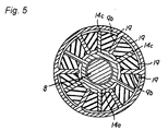
- Fig. 5 is a sectional view taken along a line B-B of Fig. 4, in these drawings, the same elements as those shown in Fig. 2 and Fig. 3 are attached with the same notations and in the following, an explanation thereof will be omitted.
- a plurality (6 according to the embodiment) of the ribs 9b for the wheel damper are radially formed (refer to Fig. 5) at the inner peripheral portion of the hub 9a of the rear wheel 9, the wheel damper 13 is integrated to a central portion of the hub 9a and a lid member 29 is attached to an end face of the hub 9a by the bolt 26 along with the brake disk 25 to thereby cover the wheel damper 13.
- the wheel damper 13 is constituted by arranging the clutch hub 14c erected radially at the outer periphery of the boss 14a of the clutch member 14 coupled to the outer periphery of the drive shaft 8 by serration coupling between the ribs 9b for the wheel damper on the side of the rear wheel 9 and interposing the damper 19 made of rubber between the clutch hub 14c and the rib 9b for the wheel damper.
- the rear wheel 9 is rotatably supported by the drive shaft 8 by ball bearings 30 and 31. Further, according to the embodiment, the parking brake 20 constituted by the drum brake is integrated to the lid member 29.
- the wheel damper 13 is integrated within the width of the rear wheel 9 and therefore, rational arrangement of the wheel damper 23 can be carried out without being accompanied by spatial difficulty and the torque variation of the engine is absorbed by the wheel damper 13 to thereby promote the ride comfort characteristic of the scooter type motorcycle 1.
- the wheel portion structure comprising:
- a scooter type motorcycle constituted by supporting rear wheel 9 by a drive shaft 8 extended from a unit swing type engine in a vehicle width direction
- the wheel portion structure including a clutch member 14 having a boss portion 14a fitted to an outer periphery of the drive shaft 8, a flange portion 14b formed at the boss portion 14a and a plurality of clutch hubs 14c erected radially from the flange portion 14b to the boss portion 14a in which the rear wheel 9 is provided with a recessed portion 9c fitted with the clutch hub 14c via a damper (elastic member) 19 and a boss portion fitted with an outer periphery of the boss portion 14a of the clutch member 14 and the boss portion 14a of the clutch member 14 and the boss portion of the rear wheel 9 are fitted to each other at the same position as that of the recessed portion 9
- the present invention relates to a scooter type motorcycle. It aims to provide improved riding comfort and fluctuating torque transmission conditions.
- Said target is performed by such a motorcycle having swing type engine unit driving a drive shaft which extends in a width direction of the vehicle, wherein a wheel damper is integrated within the width extension of the rear wheel of the vehicle.
- the present invention relates to a scooter type motorcycle. It aims to provide improved riding comfort and fluctuating torque transmission conditions.
- Said target is performed by such a motorcycle having a swing type engine unit driving a drive shaft which extends in a width direction of the vehicle, wherein a wheel damper is integrated within the width extension of the rear wheel of the vehicle.
Landscapes
- Engineering & Computer Science (AREA)
- Chemical & Material Sciences (AREA)
- Combustion & Propulsion (AREA)
- Transportation (AREA)
- Mechanical Engineering (AREA)
- Braking Arrangements (AREA)
- Arrangement Or Mounting Of Propulsion Units For Vehicles (AREA)
- Automatic Cycles, And Cycles In General (AREA)
Abstract
Description
wherein the boss portion of the clutch member and the boss portion of the rear wheel are fitted to each other at the same position as a position of the power transmitting portion of the rear wheel in a width direction.
- Fig. 1
- is a side view of a scooter type motorcycle 1 having a wheel portion structure according to the invention;
- Fig. 2
- is a sectional view of an essential portion of a rear wheel portion showing the rear wheel structure according to the embodiment 1 of the invention;
- Fig. 3
- is a sectional view taken along a line A-A of Fig. 2;
- Fig. 4
- is a sectional view of an essential portion of a rear wheel portion showing a rear wheel portion structure according to embodiment 2 of the invention; and
- Fig. 5
- is a sectional view taken along a line B-B of Fig. 4.
wherein the boss portion of the clutch member and the boss portion of the rear wheel are fitted to each other at a position the same as a position of the power transmitting portion of the rear wheel in a width direction and therefore, there is achieved the effect being capable of promoting the ride comfort characteristic by integrating the wheel damper without being accompanied by spatial difficulty.
Claims (10)
- Scooter type motorcycle having a unit swing type engine (6) driving a rear wheel (9) via a drive shaft (8) extending in a vehicle width direction,
characterized in that
the wheel damper (13) is integrated within the width of the rear wheel (9). - Scooter type motorcycle according to claim 1, characterized in that said wheel damper (13) comprises a clutch member (14) having a number of clutch hubs (14c) and being coupled to an outer periphery of the drive shaft (8),
a hub portion (9a) of said rear wheel (9) having a corresponding number of wheel ribs (9b) and being arranged rotatably about said drive shaft (8),
and damper members (19) being interposed between said clutch hubs (14c) and said wheel ribs (9b) in a circumferential direction of the drive shaft (8). - Scooter type motorcycle according to claim 2, characterized in that said clutch member (14) comprises a boss portion (14a) being fitted to said outer periphery of the drive shaft (8), a flange portion (14b) formed at said boss portion (14a) and extending in a radial direction of the drive shaft (8), wherein said number of clutch hubs (14c) extend from said flange portion (14) in an axial direction of said drive shaft (8).
- Scooter type motorcycle according to claim 3, characterized in that said flange portion (14b) is formed close to a side end of the boss portion (14a) of the clutch member (14) at a vicinity of a vehicle body center plane of the scooter type motorcycle (1).
- Scooter type motorcycle according to claim 4, characterized in that said number of clutch hubs (14c) extend in a direction away from said body center plane towards the boss portion (14a) of the clutch member (14).
- Scooter type motorcycle according to at least one of the claims 2 to 5, characterized in that said hub (9a) and said number of ribs (9b) are radially formed at one end face of said hub (9a) of the rear wheel (9) and at the vicinity of a body vehicle center plane, and wherein a number of recessed portions (9c) partitioned by the ribs (9b) are formed at the one end face of the hub (9a).
- Scooter type motorcycle according to claim 6, characterized in that a vertical wall (9d) extends radially inwardly from said hub (9a) of said rear wheel (9) contiguous to the ribs (14b) of the clutch member (14).
- Scooter type motorcycle according to claim 2, characterized in that said clutch member (14) comprises a boss portion (14a) being fitted to said outer periphery of the drive shaft (8), wherein said number of clutch hubs (14c) extend from said boss portion (14a) in radial directions outwardly.
- Scooter type vehicle according to claim 1 or 8, characterized in that said number of ribs (9b) are formed at an inner peripheral portion of a hub (9a) of the rear wheel (9) and extend radially inwardly towards a boss portion (14a) of the clutch member (14).
- Scooter type vehicle according to at least one of the claims 2 to 9, characterized in that said ribs (9b) of said rear wheel (9) for said wheel damper (13) are formed at a vicinity of a vehicle body center plane of the rear wheel (9) and in that a parking brake (20) is arranged at a vicinity of the ribs (9b) for the wheel damper (13) of the rear wheel (9).
Applications Claiming Priority (2)
| Application Number | Priority Date | Filing Date | Title |
|---|---|---|---|
| JP2001354541 | 2001-11-20 | ||
| JP2001354541A JP2003154804A (en) | 2001-11-20 | 2001-11-20 | Wheel structure of scooter type motorcycle |
Publications (2)
| Publication Number | Publication Date |
|---|---|
| EP1312544A2 true EP1312544A2 (en) | 2003-05-21 |
| EP1312544A3 EP1312544A3 (en) | 2006-02-08 |
Family
ID=19166387
Family Applications (1)
| Application Number | Title | Priority Date | Filing Date |
|---|---|---|---|
| EP02025729A Withdrawn EP1312544A3 (en) | 2001-11-20 | 2002-11-15 | Scooter type motorcycle |
Country Status (3)
| Country | Link |
|---|---|
| EP (1) | EP1312544A3 (en) |
| JP (1) | JP2003154804A (en) |
| CN (1) | CN1420051A (en) |
Cited By (3)
| Publication number | Priority date | Publication date | Assignee | Title |
|---|---|---|---|---|
| DE102005051213A1 (en) * | 2005-10-26 | 2007-05-03 | Bayerische Motoren Werke Ag | Rear suspension for motorcycles |
| JP2010522659A (en) * | 2007-03-21 | 2010-07-08 | ザ ゲイツ コーポレイション | Motorcycle wheel isolator |
| WO2011039767A3 (en) * | 2009-09-30 | 2011-05-26 | M/S.Tvs Motor Company Limited | An engine torque damping system |
Families Citing this family (8)
| Publication number | Priority date | Publication date | Assignee | Title |
|---|---|---|---|---|
| CN101821157B (en) * | 2007-10-22 | 2012-12-19 | 浜元阳一郎 | Rotation transmission mechanism for human-powered vehicles, human-powered vehicles and bicycles equipped with the same |
| US7931538B2 (en) | 2008-07-11 | 2011-04-26 | Harley-Davidson Motor Company Group, Inc. | Torque dampening compensator for a vehicle |
| US7610979B1 (en) | 2008-07-16 | 2009-11-03 | Harley-Davidson Motor Company Group, LLC | Reverse drive system for a three-wheeled vehicle |
| JP5361782B2 (en) * | 2010-03-31 | 2013-12-04 | 本田技研工業株式会社 | Wheel structure of saddle-ride type vehicle |
| JP2014021741A (en) * | 2012-07-19 | 2014-02-03 | Hitachi Omron Terminal Solutions Corp | Paper money transaction device |
| JP6188189B2 (en) * | 2013-01-30 | 2017-08-30 | 本田技研工業株式会社 | Wheel equipment |
| WO2020250460A1 (en) * | 2019-06-14 | 2020-12-17 | 株式会社Freepower Innovations | Rotation transmission mechanism and motor |
| JP6747743B1 (en) * | 2019-06-14 | 2020-08-26 | 株式会社Freepower Innovations | Rotation transmission mechanism and motor |
Family Cites Families (7)
| Publication number | Priority date | Publication date | Assignee | Title |
|---|---|---|---|---|
| US1892505A (en) * | 1925-08-24 | 1932-12-27 | Edwin R Evans | Method of making a shock insulating device |
| DE2546804A1 (en) * | 1975-10-18 | 1977-04-21 | Bayerische Motoren Werke Ag | Torque damper for motor cycle transmission - with elastic pads and asymmetric thrust ribs for thicker pads in drive direction |
| JPH0511757Y2 (en) * | 1986-09-25 | 1993-03-24 | ||
| DE3934798A1 (en) * | 1989-10-19 | 1991-04-25 | Fichtel & Sachs Ag | Torsional vibration damper with pre-curved coil springs |
| DE4204244A1 (en) * | 1992-02-13 | 1993-08-19 | Porsche Ag | DRIVE CONNECTION WITH TORQUE DAMPING IN THE DRIVETRAIN OF A MOTOR VEHICLE |
| DE9414844U1 (en) * | 1994-09-13 | 1994-11-03 | Fichtel & Sachs Ag, 97424 Schweinfurt | Torque damper for two-wheel drive |
| JP2001241507A (en) * | 2000-02-25 | 2001-09-07 | Honda Motor Co Ltd | Power transmission mechanism for motorcycle |
-
2001
- 2001-11-20 JP JP2001354541A patent/JP2003154804A/en active Pending
-
2002
- 2002-10-31 CN CN 02146701 patent/CN1420051A/en active Pending
- 2002-11-15 EP EP02025729A patent/EP1312544A3/en not_active Withdrawn
Cited By (3)
| Publication number | Priority date | Publication date | Assignee | Title |
|---|---|---|---|---|
| DE102005051213A1 (en) * | 2005-10-26 | 2007-05-03 | Bayerische Motoren Werke Ag | Rear suspension for motorcycles |
| JP2010522659A (en) * | 2007-03-21 | 2010-07-08 | ザ ゲイツ コーポレイション | Motorcycle wheel isolator |
| WO2011039767A3 (en) * | 2009-09-30 | 2011-05-26 | M/S.Tvs Motor Company Limited | An engine torque damping system |
Also Published As
| Publication number | Publication date |
|---|---|
| CN1420051A (en) | 2003-05-28 |
| JP2003154804A (en) | 2003-05-27 |
| EP1312544A3 (en) | 2006-02-08 |
Similar Documents
| Publication | Publication Date | Title |
|---|---|---|
| EP1582450B1 (en) | Bicycle drive unit | |
| US6910987B2 (en) | Automatic transmission for light vehicles employing V-Twin engines | |
| KR100498819B1 (en) | Planetary transmission for a vehicle | |
| EP0198297B1 (en) | Device for direct driving of wheels | |
| JP2014029199A (en) | Travel driving device for dump truck | |
| US20190126747A1 (en) | A planet carrier and a planetary gear transmission | |
| JP5256783B2 (en) | Hybrid drive device | |
| JPH0765633B2 (en) | Centrifugal clutch | |
| JP2003154804A (en) | Wheel structure of scooter type motorcycle | |
| US7828108B2 (en) | Rear drive and suspension for an all terrain vehicle | |
| JP4886319B2 (en) | Vehicle deceleration device | |
| US4615423A (en) | Hub for a two-wheeled vehicle | |
| WO2004078509A1 (en) | Device for driving a vehicle wheel | |
| JP2009501103A5 (en) | ||
| JP5506223B2 (en) | Motor drive vehicle | |
| KR101294035B1 (en) | Structure of axle assembly for a driving wheel | |
| JP4476576B2 (en) | Parking brake structure | |
| EP4048580B1 (en) | A drive system for a side mounted cycle wheel | |
| JP5654389B2 (en) | Continuous transmission structure | |
| JP6411879B2 (en) | Saddle riding vehicle | |
| JP4294897B2 (en) | Brake structure of motorcycle | |
| JP4396259B2 (en) | Wheel structure for electric vehicles | |
| JP4873568B2 (en) | Brake structure of motorcycle | |
| EP4628754A1 (en) | Continuously variable transmission and straddled vehicle including continuously variable transmission | |
| JP4282973B2 (en) | Power transmission device for small vehicles |
Legal Events
| Date | Code | Title | Description |
|---|---|---|---|
| PUAI | Public reference made under article 153(3) epc to a published international application that has entered the european phase |
Free format text: ORIGINAL CODE: 0009012 |
|
| AK | Designated contracting states |
Designated state(s): AT BE BG CH CY CZ DE DK EE ES FI FR GB GR IE IT LI LU MC NL PT SE SK TR |
|
| AX | Request for extension of the european patent |
Extension state: AL LT LV MK RO SI |
|
| PUAL | Search report despatched |
Free format text: ORIGINAL CODE: 0009013 |
|
| AK | Designated contracting states |
Kind code of ref document: A3 Designated state(s): AT BE BG CH CY CZ DE DK EE ES FI FR GB GR IE IT LI LU MC NL PT SE SK TR |
|
| AX | Request for extension of the european patent |
Extension state: AL LT LV MK RO SI |
|
| 17P | Request for examination filed |
Effective date: 20060110 |
|
| AKX | Designation fees paid |
Designated state(s): DE ES FR IT |
|
| STAA | Information on the status of an ep patent application or granted ep patent |
Free format text: STATUS: THE APPLICATION IS DEEMED TO BE WITHDRAWN |
|
| 18D | Application deemed to be withdrawn |
Effective date: 20061018 |