EP1312498A2 - Horizontal transmission and oil system for telehandlers - Google Patents
Horizontal transmission and oil system for telehandlers Download PDFInfo
- Publication number
- EP1312498A2 EP1312498A2 EP02020301A EP02020301A EP1312498A2 EP 1312498 A2 EP1312498 A2 EP 1312498A2 EP 02020301 A EP02020301 A EP 02020301A EP 02020301 A EP02020301 A EP 02020301A EP 1312498 A2 EP1312498 A2 EP 1312498A2
- Authority
- EP
- European Patent Office
- Prior art keywords
- transmission
- prime mover
- output
- cooling system
- work machine
- Prior art date
- Legal status (The legal status is an assumption and is not a legal conclusion. Google has not performed a legal analysis and makes no representation as to the accuracy of the status listed.)
- Granted
Links
- 230000005571 horizontal transmission Effects 0.000 title 1
- 230000005540 biological transmission Effects 0.000 claims abstract description 185
- 238000001816 cooling Methods 0.000 claims abstract description 77
- MROJXXOCABQVEF-UHFFFAOYSA-N Actarit Chemical compound CC(=O)NC1=CC=C(CC(O)=O)C=C1 MROJXXOCABQVEF-UHFFFAOYSA-N 0.000 claims abstract 25
- 239000003921 oil Substances 0.000 claims description 19
- 239000000463 material Substances 0.000 claims description 15
- 239000010687 lubricating oil Substances 0.000 claims description 13
- 239000010720 hydraulic oil Substances 0.000 claims description 9
- 230000000712 assembly Effects 0.000 claims description 6
- 238000000429 assembly Methods 0.000 claims description 6
- 230000008878 coupling Effects 0.000 claims description 6
- 238000010168 coupling process Methods 0.000 claims description 6
- 238000005859 coupling reaction Methods 0.000 claims description 6
- 238000004519 manufacturing process Methods 0.000 claims description 3
- 239000012530 fluid Substances 0.000 description 7
- 230000008901 benefit Effects 0.000 description 4
- 238000010276 construction Methods 0.000 description 3
- 239000002826 coolant Substances 0.000 description 3
- 238000010586 diagram Methods 0.000 description 3
- 230000007246 mechanism Effects 0.000 description 2
- 230000004075 alteration Effects 0.000 description 1
- 150000001875 compounds Chemical class 0.000 description 1
- 230000006835 compression Effects 0.000 description 1
- 238000007906 compression Methods 0.000 description 1
- 238000006073 displacement reaction Methods 0.000 description 1
- 230000001050 lubricating effect Effects 0.000 description 1
- 238000000034 method Methods 0.000 description 1
- 238000012986 modification Methods 0.000 description 1
- 230000004048 modification Effects 0.000 description 1
- 230000009467 reduction Effects 0.000 description 1
- 230000004044 response Effects 0.000 description 1
- XLYOFNOQVPJJNP-UHFFFAOYSA-N water Substances O XLYOFNOQVPJJNP-UHFFFAOYSA-N 0.000 description 1
Images


Classifications
-
- B—PERFORMING OPERATIONS; TRANSPORTING
- B66—HOISTING; LIFTING; HAULING
- B66F—HOISTING, LIFTING, HAULING OR PUSHING, NOT OTHERWISE PROVIDED FOR, e.g. DEVICES WHICH APPLY A LIFTING OR PUSHING FORCE DIRECTLY TO THE SURFACE OF A LOAD
- B66F9/00—Devices for lifting or lowering bulky or heavy goods for loading or unloading purposes
- B66F9/06—Devices for lifting or lowering bulky or heavy goods for loading or unloading purposes movable, with their loads, on wheels or the like, e.g. fork-lift trucks
- B66F9/075—Constructional features or details
- B66F9/07595—Cooling arrangements for device or operator
-
- B—PERFORMING OPERATIONS; TRANSPORTING
- B60—VEHICLES IN GENERAL
- B60K—ARRANGEMENT OR MOUNTING OF PROPULSION UNITS OR OF TRANSMISSIONS IN VEHICLES; ARRANGEMENT OR MOUNTING OF PLURAL DIVERSE PRIME-MOVERS IN VEHICLES; AUXILIARY DRIVES FOR VEHICLES; INSTRUMENTATION OR DASHBOARDS FOR VEHICLES; ARRANGEMENTS IN CONNECTION WITH COOLING, AIR INTAKE, GAS EXHAUST OR FUEL SUPPLY OF PROPULSION UNITS IN VEHICLES
- B60K11/00—Arrangement in connection with cooling of propulsion units
- B60K11/02—Arrangement in connection with cooling of propulsion units with liquid cooling
-
- B—PERFORMING OPERATIONS; TRANSPORTING
- B60—VEHICLES IN GENERAL
- B60K—ARRANGEMENT OR MOUNTING OF PROPULSION UNITS OR OF TRANSMISSIONS IN VEHICLES; ARRANGEMENT OR MOUNTING OF PLURAL DIVERSE PRIME-MOVERS IN VEHICLES; AUXILIARY DRIVES FOR VEHICLES; INSTRUMENTATION OR DASHBOARDS FOR VEHICLES; ARRANGEMENTS IN CONNECTION WITH COOLING, AIR INTAKE, GAS EXHAUST OR FUEL SUPPLY OF PROPULSION UNITS IN VEHICLES
- B60K17/00—Arrangement or mounting of transmissions in vehicles
- B60K17/04—Arrangement or mounting of transmissions in vehicles characterised by arrangement, location or kind of gearing
-
- B—PERFORMING OPERATIONS; TRANSPORTING
- B60—VEHICLES IN GENERAL
- B60K—ARRANGEMENT OR MOUNTING OF PROPULSION UNITS OR OF TRANSMISSIONS IN VEHICLES; ARRANGEMENT OR MOUNTING OF PLURAL DIVERSE PRIME-MOVERS IN VEHICLES; AUXILIARY DRIVES FOR VEHICLES; INSTRUMENTATION OR DASHBOARDS FOR VEHICLES; ARRANGEMENTS IN CONNECTION WITH COOLING, AIR INTAKE, GAS EXHAUST OR FUEL SUPPLY OF PROPULSION UNITS IN VEHICLES
- B60K17/00—Arrangement or mounting of transmissions in vehicles
- B60K17/34—Arrangement or mounting of transmissions in vehicles for driving both front and rear wheels, e.g. four wheel drive vehicles
-
- B—PERFORMING OPERATIONS; TRANSPORTING
- B66—HOISTING; LIFTING; HAULING
- B66F—HOISTING, LIFTING, HAULING OR PUSHING, NOT OTHERWISE PROVIDED FOR, e.g. DEVICES WHICH APPLY A LIFTING OR PUSHING FORCE DIRECTLY TO THE SURFACE OF A LOAD
- B66F9/00—Devices for lifting or lowering bulky or heavy goods for loading or unloading purposes
- B66F9/06—Devices for lifting or lowering bulky or heavy goods for loading or unloading purposes movable, with their loads, on wheels or the like, e.g. fork-lift trucks
- B66F9/065—Devices for lifting or lowering bulky or heavy goods for loading or unloading purposes movable, with their loads, on wheels or the like, e.g. fork-lift trucks non-masted
- B66F9/0655—Devices for lifting or lowering bulky or heavy goods for loading or unloading purposes movable, with their loads, on wheels or the like, e.g. fork-lift trucks non-masted with a telescopic boom
-
- E—FIXED CONSTRUCTIONS
- E02—HYDRAULIC ENGINEERING; FOUNDATIONS; SOIL SHIFTING
- E02F—DREDGING; SOIL-SHIFTING
- E02F9/00—Component parts of dredgers or soil-shifting machines, not restricted to one of the kinds covered by groups E02F3/00 - E02F7/00
- E02F9/08—Superstructures; Supports for superstructures
- E02F9/0858—Arrangement of component parts installed on superstructures not otherwise provided for, e.g. electric components, fenders, air-conditioning units
- E02F9/0866—Engine compartment, e.g. heat exchangers, exhaust filters, cooling devices, silencers, mufflers, position of hydraulic pumps in the engine compartment
Definitions
- This invention relates to a power train arrangement, and more particularly to a power train arrangement for work machines, such as material handling machines.
- Work machines such as material handling machines for use at construction sites typically have large diameter front and rear wheels driven by a power train. These material handling machines are designed to carry out given tasks such as digging, loading, or pallet-lifting. The relatively large wheels place a constraint on the arrangement of the machine's power train components and operator's cabin.
- One known material handling machine for use at construction sites is a telescopic handler.
- This machine has an elongated main frame defined by first and second substantially parallel and vertically oriented side members that are spaced apart to form a longitudinally extending gap centered about a longitudinal vertical center plane of the material handling machine.
- a boom is pivotally connected at one end of the boom to a back end portion of the main frame and extends parallel to the center plane of the material handling machine so that a second end of the boom passes a front end portion of the main frame.
- the boom may have an implement mounted at its second end for performing an intended work function.
- An operator's cabin is typically located to one side of the boom, while the engine, cooling system, and transmission are located to a second side of the boom.
- the above configuration generally provides good operator visibility in all directions, except the direction in which the engine, cooling system, and transmission obstruct the operator's visibility.
- the cooling system, engine, and transmission are mounted serially in that order to the main frame. That is, the engine is disposed between the transmission and the cooling system.
- the material handling machine further includes front and rear axles mounted beneath the main frame to complete the power train to wheels that are carried by the front and rear axles.
- a front differential couples the front axle to a first drive shaft
- a rear differential couples the rear axle to a second drive shaft.
- Both first and second drive shafts extend longitudinally beneath the longitudinally extending gap formed by the side members of the main frame. Hydraulically actuated piston-cylinder devices may be used to steer the wheels.
- the transmission which can include a reducing transmission, is required to overcome significant vertical and lateral distances in order to transmit torque from the engine to the differentials.
- severe drive shaft angles are created that can cause vibration and wear in the power train.
- the larger the material handling machine the more severe the drive shaft angles can be, since the main frames are wider on the larger machines. Therefore, different cooling system, engine, and transmission designs are required for different size machines to adapt to the different sizes of the main frames.
- the weight of the engine cannot be effectively used as a counter weight against a load at the front end of the material handling machine, such as a load carried by the boom in the case of a telescopic handler.
- U.S. Patent No. 6,105,710 discloses a material handling machine in which an engine is arranged outside the longitudinal center plane of the machine, and a transmission is coupled to one end of the engine through a torque converter at one end of the engine opposite to where the cooling system is connected.
- the transmission includes a reducing transmission coupled to an output shaft of the engine for reducing the number of revolutions of the engine's output shaft, and a transfer transmission that takes an output torque from the reducing transmission and transmits this torque to the drive shafts.
- U.S. Patent 6,152,253 discloses a drive train arrangement for a construction vehicle wherein a side frame member extends laterally from a central frame member of the vehicle and defines a drive train receiving space for an engine, transmission and transfer case.
- the engine and transmission are oriented in a side-by-side configuration and connected via the transfer case such that the transmission input and output extend along an axis coincident with the longitudinal axis of the central frame member.
- the transfer case Due to the positioning of the transmission along an axis coincident with the longitudinal axis of the central frame member, the transfer case is disposed in a manner that laterally offsets the engine and the transmission.
- the positioning of the drive train components in this manner limits loading and spacing advantages available on the vehicle and ignores valuable and efficient connecting relationships between the components.
- the present invention is directed to overcoming one or more of the problems as set forth above.
- a power train arrangement comprises a prime mover, a cooling system; and a transmission coupled to the prime mover and the cooling system with the transmission positioned intermediate the prime mover and the cooling system.
- a work machine has front and rear ends and a main frame.
- a prime mover, transmission and cooling system are connected to a platform to define a module releasably connected to the main frame.
- the prime mover, transmission and cooling system are interconnected in a predetermined manner so that the prime mover is positioned rearwardly from the transmission and the cooling system in relation to the front end of the work machine.
- the work machine also includes front and rear wheels.
- a front drive shaft is coupled to the transmission for transmitting a first torque to the front wheel and has a predetermined length.
- a rear drive shaft is coupled to the transmission for transmitting a second torque to the rear wheel and has a predetermined length equal to the predetermined length of the front drive shaft.
- a method of manufacturing a plurality of work machines includes a first work machine that has a first main frame and a second work machine that has a second main frame with the second main frame being larger than the first main frame.
- the method comprises the steps of providing two prime movers, two transmissions, two cooling systems, and two platforms.
- assembling a first module and a second module so that each of the first and second modules include one of the two prime movers, one of the two transmissions, and one of the two cooling systems respectively mounted to one of the two platforms.
- mounting the first module to the first main frame and mounting the second module to the second main frame.
- the present invention provides a work machine that can carry out operations, such as lifting, loading, and digging, with essential components, including the engine, transmission and cooling system arranged in a manner to optimize the mechanical and functional operation of the work machine.
- the work machine 100 includes a chassis or main frame 101 having a front end 102 and a rear end 103 with a longitudinal axis X-X extending between the front end 102 and the rear end 103 and passing through a longitudinal vertical center plane P of the work machine 100.
- the main frame 101 has an elongated configuration defined by first and second substantially parallel and spaced apart side members 104, 105, which are oriented vertically.
- the work machine 100 is a telescopic handler having a telescopic boom 201 that is pivotally connected to the main frame 101 at the rear end 103. While the present invention is described with reference to a telescopic handler, other work machines, such as loaders, backhoes, non-telescopic handlers and the like are within the scope of the invention.
- An extremity or distal end 202 of the boom 201 can be fitted with an attachment, such as a pallet lifting fork or the like.
- the longitudinal centerline of the boom 201 lies in the longitudinal vertical center plane P of the work machine.
- the boom 201 can be raised and lowered, as well as extended and shortened, by hydraulic cylinders and pistons (not shown), as is well known.
- the work machine 100 experiences the greatest moment force M that urges the work machine 100 about its front end 102 when the boom 201 is fully extended. Therefore, proper distribution of the work machine's weight along the longitudinal axis X-X is important for maximizing the load carrying capability of the work machine 100 and ensuring that the work machine 100 is stable at maximum carrying loads.
- the work machine 100 is equipped with large front and rear wheels 106, which are rotatably supported on respective front and rear axles 107, 108.
- the front and rear axles 107, 108 are connected to the main frame 101 near the front and rear ends 102, 103 of the main frame 101, respectively, and extend transversely relative to the longitudinal axis X-X of the main frame 101.
- the large front and rear wheels 106 limit the available space for other essential components of the work machine 100. Seen specifically in Fig. 2, both the front and rear wheels 106 can be pivotable about a respective vertical steering axis S-S for steering the work machine 100, further limiting the available space in which to arrange other essential components of the work machine 100.
- the front and rear axles 107, 108 are provided with respective front and rear differentials 109, 110, which are also preferably located in the longitudinal vertical center plane P of the work machine 100.
- a front drive shaft 120 leads to the front differential 109 for driving that differential.
- a rear drive shaft 121 leads to the rear differential 110 for driving that differential.
- the front and rear drive shafts 120, 121 may lie in the longitudinal center plane P of work machine 100 and may be co-linear with respect to each other. Alternatively, these drive shafts may be angled with respect to the longitudinal vertical center plane P and/or with respect to each other as shown in Fig. 1.
- the work machine 100 has a prime mover 111, for example a heat engine such as a compression ignition or diesel engine, for generating the required torque to move the work machine 100 as well as power to operate various auxiliary components of the work machine 100, including hydraulics pumps for actuating the hydraulic pistons and cylinders (not shown).
- the prime mover 111 is upright and located to a first side 112 of the main frame 101. Seen specifically in Fig. 4, the prime mover is preferably fixed to a platform 137 that is attached to the main frame 101 in any suitable manner, preferably, releasably mounted via a plurality of bolts (not shown).
- the longitudinal centerline E-E of the prime mover 111 may be set at an angle with respect to the longitudinal axis X-X of the main frame 101, but is preferably parallel to the longitudinal axis X-X as shown in Fig. 5.
- the work machine 100 has a transmission 113 for transmitting torque from the prime mover 111 to the wheels 106.
- the transmission 113 is also preferably fixed to the platform 137 that is attached to the main frame 101.
- the transmission 113 includes a housing 114 that houses an input gear assembly 115 and an output gear assembly 116, and may also include an intermediate gear assembly 117, as seen best in Fig. 6.
- the housing 114 is rigidly coupled to the prime mover 111 at one end, for example, the front end of the prime mover as shown in Fig. 5.
- an automatic transmission seen best in Figs.
- the transmission 113 includes a torque converter 118 coupled thereto, also disposed within the housing 114, to provide a fluid coupling between an output shaft 119 of the prime mover 111 and the input gear assembly 115 of the transmission 113. While the present invention is described with respect to an automatic transmission, other transmissions, such as simple or compound mechanical change-gear transmissions that can be shifted using manual, semiautomatic, or fully automatic actuators to select one of a number of gear ratios between an input shaft and an output shaft of the transmission are within the scope of the present invention.
- the input gear assembly 115 of the transmission 113 is rotatable in response to rotation of the output shaft 119 of the prime mover 111, such as a crankshaft, through the torque converter 118.
- the rotational axes of the transmission's input, output and intermediate gear assemblies 115-117 are set to be preferably parallel to the rotational axis of the output shaft 119 of the prime mover 111, which, in turn, is preferably parallel to the longitudinal axis X-X of the main frame 101.
- This parallel alignment reduces the complexity of the transmission 113, since it eliminates the requirement for beveled gears to compensate for any offset angle between the transmission 113 and the prime mover 111 and/or the front and rear drive shafts 120, 121.
- the rotational axis of the input gear assembly 115 may be preferably coaxial with the rotational axis of the output shaft 119 of the prime mover 111.
- the intermediate gear assembly 117 kinematically couples the input gear assembly 115 to the output gear assembly 116 in a manner that directionally offsets the output gear assembly 116 orthogonal from the rotational axis of the input gear assembly 115.
- the intermediate gear assembly 117 includes an idler gear 117a.
- the transmission 113 extends laterally to a location where the rotational axis of the transmission output gear assembly 116 lies in or near the longitudinal vertical center plane P of the work machine 100.
- the transmission 113 may also extend vertically downward to a location beneath the main frame 101 so that the rotational axis of the transmission output gear assembly 116 is co-linear, or as near as possible to being co-linear, with the front and rear drive shafts 120, 121.
- the transmission 113, and in particular the transmission's output gear assembly 116 are preferably coupled to the front and rear drive shafts 120, 121 at a longitudinal position equidistant to the front and rear differentials 109, 110.
- This arrangement allows the front and rear drive shafts 102, 121 to have substantially equal lengths, thereby ensuring that the drive shaft angles ⁇ f , ⁇ r , ⁇ f , ⁇ r are minimized by maximizing the length of the shortest drive shaft.
- the coupling between the output gear assembly 116 and the front and rear drive shafts can be made through respective front and rear yokes 116a, 116b connected to a transmission output shaft 116c of the output gear assembly 116, seen in Fig. 6.
- Positioning the transmission 113 at a position equidistant between the front and rear differentials 109, 110 is accomplished by having the transmission 113 intermediate to the prime mover 111 and an associated cooling system 122. Therefore, the prime mover 111, transmission 113, and cooling system 122 are serially aligned in that order relative from the rear end 103 of the work machine 100.
- the cooling system 122 is associated with the prime mover 111 and is preferably fixed to the platform 137 that is attached to the main frame 101.
- the cooling system 122 includes a heat exchanger 123, such as a radiator, that provides fluid-to-air heat exchange for a coolant that circulates throughout a cooling jacket (not shown) to cool the prime mover 111.
- a fan 125 is provided on a side of the heat exchanger 123 facing the prime mover 111 to force air across the heat exchanger 123 in a known manner.
- the cooling system 122 also circulates coolant past a hydraulic fluid heat exchanger (not shown) to cool hydraulic fluid used in the work machine 100.
- the transmission 113 is disposed between the prime mover 111 and the cooling system 122. Therefore, as seen best diagrammatically in Fig. 8, one side of the transmission 113 (e.g., the rear side) is kinematically coupled to the prime mover 111 via the torque converter 118 to drive the front and rear drive shafts 120,121 through the transmission gear assemblies 115,116 and 117. In this manner, the prime mover 111 may be connected and disconnected from the front and rear drive shafts 120 and 121 in a manner that allows the work machine 100 to remain stopped while the engine continues running.
- a torque converter 118 is used, it should be understood that any suitable coupling, such as a friction clutch or the like, may be used to connect the prime mover 111 with the transmission 113.
- the other side of the transmission 113 (e.g., the front side) is coupled to the fan 125 of the cooling system 122 through a drive fan assembly 126 so that the prime mover 111 drives the fan 125.
- the coupling of the prime mover with the cooling system 122 occurs through a series of gears 126a and idler gear 117a included in the drive fan assembly 126 which are disposed within the housing 114.
- the fan drive assembly 126 of the transmission 113 is shown in more detail without the cooling system 122 in order to improve clarity.
- the fan 125 is mechanically driven directly by a fan drive output 127.
- the fan drive output 127 is a pulley rotatably coupled to the prime mover 111 through the transmission 113 and driven by a fan drive input pulley 128 and a belt 129.
- the prime mover 111 and the fan drive input pulley 128 are connected through the series of gears 126a and idler gear 117a.
- the rotational axes of the fan drive output 127 and fan drive input 128 are substantially parallel to the rotational axis of the output shaft 119 of the prime mover 111.
- the rotational axes of the fan drive output 127 or fan drive input 128 may be coaxial with the rotational axis of the output shaft 119 of the prime mover 111. While the present invention is described as a direct fan drive assembly 126, other fan mechanisms, such as hydraulic various displacement pump and fluid motor fan drives are within the scope of the present invention.
- the prime mover 111, transmission 113, and cooling system 122 are preferably mounted on or fixed to the platform 137, thereby forming a subassembly or module 139, seen best in Fig. 4, that can be separately assembled and then secured (e.g., bolted) to the main frame 101.
- the module 139 may also include a surrounding enclosure 136.
- an operator's cabin 130 is mounted to the main frame 101 and located to a second side 131 of the main frame 101 opposite to the first side 112 at which the prime mover 111 is located.
- the operator's cabin 130 has a front window 132, a rear window 133, and two side windows 134 and 135 to provide an operator (not shown) with visibility in all directions.
- the transmission 113 is centered in a longitudinal direction on the work machine 100 and opposes the operator's cabin 130, it is preferable to place the transmission 113 at a relatively low position on the work machine 100 to avoid interference with the operator's cabin 130.
- the work machine 100 must have a minimum ground clearance H 1 as shown in Figs. 2 and 3, and the work machine's chassis or main frame 101 must be sufficiently strong to withstand the loads placed on the work machine 100. Therefore, the transmission 113 should preferably be placed within the narrow space H 2 provided between the minimum ground clearance H 1 and a bottom portion 138 of the main frame 101 that defines a lower limit of the longitudinally extending gap for the boom 201.
- the transmission 113 is preferably made relatively flat or with a slightly curved profile as shown in Figs. 4, 6, and 7. Since the output of the prime mover 111 is positioned above the drive shafts 120 and 121, the transmission 113 may also be downwardly sloped. Additional gears may be used inside the transmission housing 114 as required to extend the transmission output gear assembly 116 to the drive shafts 120 and 121.
- the work machine 100 has a common oil system or circuit, generally indicated at 500 that combines both a transmission lubricating oil system 501 and a hydraulic oil system 502.
- the common oil system includes a common tank 503 that is shared by the transmission lubricating oil system 501 and the hydraulic oil system 502, a main pump (also referred to as an implement pump) 504 that draws oil from the common tank 503 for providing hydraulic pressure to the work machine's actuating pistons and cylinders (not shown), a charge pump 505 the draws oil from the common tank 503 and feeds it to the torque converter 118 and the transmission 113 and a scavenge pump 506 that draws oil from the transmission sump 508 and returns it to the common tank 503.
- a main pump also referred to as an implement pump
- the transmission lubricating oil system 501 At some stage in the transmission lubricating oil system 501, for example after the oil passes through the torque converter 118, the oil passes through an oil-to-water heat exchanger (not shown) that transfers heat from the lubricating oil to the coolant in the cooling system 122. Furthermore, an oil filter 507 is included, and is preferably placed at the outlet of the charge pump 505 because of the constant flow of oil, to filter the oil shared by both the transmission lubricating oil system 501 and hydraulic oil system 502. Accordingly, the transmission lubricating oil system 501 functions as the filter and cooling circuit for the oil in the common tank 503.
- the transmission 113 is positioned between the prime mover 111 and cooling system 122, additional room is created to position the main or implement pump 504 parallel to the prime mover 111, which are conventionally placed in series, thereby enabling a shorter prime mover 111 and transmission 113.
- the main or implement pump 504 is driven by a shaft 509, seen best in Fig. 6, that is rotatably coupled to the prime mover 111 through the same series of gears 126a that couple the prime mover 111 with the cooling system 122.
- the power train arrangement 90 including the prime mover 111, transmission 113, and cooling system 122 are located on one side of a work machine 100, opposite to the operator's cabin 130.
- the prime mover 111, transmission 113, and cooling system 122 are preferably fixed to the platform 137 to form a subassembly or module 139.
- the operator generally has good visibility in all directions, except the direction in which the prime mover 111, transmission 113, and cooling system 122 obstruct the operator's visibility. Accordingly, the operator's visibility can be substantially improved by lowering the module 139, that is, by lowering the prime mover 111, transmission 113, cooling system 122, and surrounding enclosure 136.
- the transmission 113 is made relative flat to fit within the narrow space H 2 provided between the minimum ground clearance H 1 of the work machine 100 and the bottom portion 138 of the main frame 101 that defines a lower limit of the longitudinally extending gap for the boom 201.
- the narrow space H 2 provided for the transmission 113 in its sloped configuration restricts the space available for a traditional splash lubricating system, wherein a sufficient level of fluid is maintained in the transmission's sump 508.
- the transmission 113 may be dry-sumped and the lubricating oil pumped to a tank as explained below. Using this dry-sumped configuration, the transmission gear assemblies 115-117 are not retarded due to hydrodynamic drag. Furthermore, a dipstick is not required to ensure that a sufficient level of fluid is maintained within the transmission sump 508.
- a common oil tank 503 is used to supply oil to both the transmission lubricating oil system 501 and the hydraulic oil system 502.
- the common tank 503 In order for the transmission lubricating oil system 501 and the hydraulic oil system 502 to draw oil from the common tank 503, the common tank 503 must be sufficiently large to provide the required fluid capacity. This is made possible due to the positioning of the transmission 113 intermediate to the prime mover 111 and cooling system 122, which eliminates the need for a transfer gear case, and allows for the positioning of the main or implement pump 505 parallel to the prime mover 111, increasing spatial capabilities for the power train arrangement 90.
- the present invention power train arrangement 90 can be used on work machines having different size chassis with little or no alteration to the design of the power train arrangement 90. Because the lateral distance between the front and rear drive shafts 120, 121 and the prime mover 111 can vary depending on the size of the work machine, and in particular the width of the main frame 101, the drive shaft angles can vary by several degrees among different size work machines. However, by placing the transmission 113 between the prime mover 111 and the cooling system 122 so as to substantially center the transmission output gear assembly 116 between the front and rear drive shafts 120, 121, the same subassembly or module 139 design can be used for different size work machines, while maintaining acceptable drive shaft angles.
- the transmission 113 is compactly designed so that the housing 114 encapsulates all transmission components and is positioned to eliminate the need for a transfer gear case. Furthermore, the transmission 113 is positioned for connection with the prime mover 111 at the rear side and the fan drive assembly 126 at the front side through the series of gears 126a. Therefore, the transmission 113 simultaneously and drivingly connects the front and rear drive shafts 120,121 and the fan 125 to the prime mover 111 through gearing mechanisms within the housing 114. This ability reduces spatial requirements and connections necessary in typical drive systems wherein the cooling system is directly connected with the prime mover 111. Additionally, the mechanical fan drive assembly 126 is simple, more efficient, and can be easily configured when coupled to the prime mover 111 through the transmission 113.
- Another advantage of placing the transmission 113 between the prime mover 111 and the cooling system 122 is that proper distribution of the work machine's weight along the longitudinal axis X-X is obtained to counter the moment force M.
- the position of the prime mover 111 at a more rearward position than the transmission 113 and cooling system 122 places the greatest proportion of load (weight) farther away from the front end of the work machine 100 to maximize the load carrying capability of the work machine 100 and ensure that the work machine 100 is more stable at maximum carrying loads.
Landscapes
- Engineering & Computer Science (AREA)
- Transportation (AREA)
- Structural Engineering (AREA)
- Mechanical Engineering (AREA)
- Chemical & Material Sciences (AREA)
- Combustion & Propulsion (AREA)
- Civil Engineering (AREA)
- Life Sciences & Earth Sciences (AREA)
- Geology (AREA)
- General Engineering & Computer Science (AREA)
- Mining & Mineral Resources (AREA)
- General Details Of Gearings (AREA)
- Cooling, Air Intake And Gas Exhaust, And Fuel Tank Arrangements In Propulsion Units (AREA)
- Arrangement Of Transmissions (AREA)
- Component Parts Of Construction Machinery (AREA)
- Friction Gearing (AREA)
- Motor Power Transmission Devices (AREA)
Abstract
Description
- This invention relates to a power train arrangement, and more particularly to a power train arrangement for work machines, such as material handling machines.
- Work machines such as material handling machines for use at construction sites typically have large diameter front and rear wheels driven by a power train. These material handling machines are designed to carry out given tasks such as digging, loading, or pallet-lifting. The relatively large wheels place a constraint on the arrangement of the machine's power train components and operator's cabin.
- One known material handling machine for use at construction sites is a telescopic handler. This machine has an elongated main frame defined by first and second substantially parallel and vertically oriented side members that are spaced apart to form a longitudinally extending gap centered about a longitudinal vertical center plane of the material handling machine. A boom is pivotally connected at one end of the boom to a back end portion of the main frame and extends parallel to the center plane of the material handling machine so that a second end of the boom passes a front end portion of the main frame. The boom may have an implement mounted at its second end for performing an intended work function. An operator's cabin is typically located to one side of the boom, while the engine, cooling system, and transmission are located to a second side of the boom. The above configuration generally provides good operator visibility in all directions, except the direction in which the engine, cooling system, and transmission obstruct the operator's visibility.
- In the known material handling machine, such as the telescopic handler described above, the cooling system, engine, and transmission are mounted serially in that order to the main frame. That is, the engine is disposed between the transmission and the cooling system. In the case of a four wheel drive system, the material handling machine further includes front and rear axles mounted beneath the main frame to complete the power train to wheels that are carried by the front and rear axles. A front differential couples the front axle to a first drive shaft, and a rear differential couples the rear axle to a second drive shaft. Both first and second drive shafts extend longitudinally beneath the longitudinally extending gap formed by the side members of the main frame. Hydraulically actuated piston-cylinder devices may be used to steer the wheels.
- Since the engine is arranged outside the longitudinal vertical center plane of the material handling machine and is elevated with respect to the machine's differentials, the transmission, which can include a reducing transmission, is required to overcome significant vertical and lateral distances in order to transmit torque from the engine to the differentials. As a result, severe drive shaft angles are created that can cause vibration and wear in the power train. Additionally, the larger the material handling machine, the more severe the drive shaft angles can be, since the main frames are wider on the larger machines. Therefore, different cooling system, engine, and transmission designs are required for different size machines to adapt to the different sizes of the main frames.
- Furthermore, since the engine is arranged between the transmission and cooling system, the weight of the engine cannot be effectively used as a counter weight against a load at the front end of the material handling machine, such as a load carried by the boom in the case of a telescopic handler.
- For example, U.S. Patent No. 6,105,710 discloses a material handling machine in which an engine is arranged outside the longitudinal center plane of the machine, and a transmission is coupled to one end of the engine through a torque converter at one end of the engine opposite to where the cooling system is connected. The transmission includes a reducing transmission coupled to an output shaft of the engine for reducing the number of revolutions of the engine's output shaft, and a transfer transmission that takes an output torque from the reducing transmission and transmits this torque to the drive shafts.
- Since the transmission disclosed in U.S. Patent No. 6,105,710 is coupled to one end of the engine at a side of the engine opposite to where the cooling system is connected, the transmission is coupled to the drive shafts at a position off-center with respect to the front and rear differentials. Consequently, one of the drive shafts is shorter than the other, resulting in a severe drive shaft angle for at least the shorter shaft. Furthermore, since the engine is disposed forward of the transmission, the engine's weight cannot be effectively used as a counter weight against a load at the front end of the material handling machine, such as a load carried by the boom in the case of a telescopic handler.
- Additionally, U.S. Patent 6,152,253 discloses a drive train arrangement for a construction vehicle wherein a side frame member extends laterally from a central frame member of the vehicle and defines a drive train receiving space for an engine, transmission and transfer case. The engine and transmission are oriented in a side-by-side configuration and connected via the transfer case such that the transmission input and output extend along an axis coincident with the longitudinal axis of the central frame member.
- Due to the positioning of the transmission along an axis coincident with the longitudinal axis of the central frame member, the transfer case is disposed in a manner that laterally offsets the engine and the transmission. The positioning of the drive train components in this manner limits loading and spacing advantages available on the vehicle and ignores valuable and efficient connecting relationships between the components.
- The present invention is directed to overcoming one or more of the problems as set forth above.
- It would, therefore, be desirable to provide a work machine that can carry out operations, such as lifting, loading, and digging, and in which essential components, including the engine and transmission, are arranged to optimize the mechanical and functional operation of the machine.
- In one aspect of the present invention, a power train arrangement, comprises a prime mover, a cooling system; and a transmission coupled to the prime mover and the cooling system with the transmission positioned intermediate the prime mover and the cooling system.
- According to another aspect of the present invention, a work machine has front and rear ends and a main frame. A prime mover, transmission and cooling system are connected to a platform to define a module releasably connected to the main frame. The prime mover, transmission and cooling system are interconnected in a predetermined manner so that the prime mover is positioned rearwardly from the transmission and the cooling system in relation to the front end of the work machine. The work machine also includes front and rear wheels. A front drive shaft is coupled to the transmission for transmitting a first torque to the front wheel and has a predetermined length. A rear drive shaft is coupled to the transmission for transmitting a second torque to the rear wheel and has a predetermined length equal to the predetermined length of the front drive shaft.
- According to yet another aspect of the present invention, a method of manufacturing a plurality of work machines is disclosed that includes a first work machine that has a first main frame and a second work machine that has a second main frame with the second main frame being larger than the first main frame. The method comprises the steps of providing two prime movers, two transmissions, two cooling systems, and two platforms. Then, assembling a first module and a second module so that each of the first and second modules include one of the two prime movers, one of the two transmissions, and one of the two cooling systems respectively mounted to one of the two platforms. Next, coupling the transmission of each of the first and second modules to the respective prime mover and respective cooling system in a manner that disposes the transmission intermediate to the prime mover and the cooling system. Finally, mounting the first module to the first main frame and mounting the second module to the second main frame.
- The present invention provides a work machine that can carry out operations, such as lifting, loading, and digging, with essential components, including the engine, transmission and cooling system arranged in a manner to optimize the mechanical and functional operation of the work machine.
- The above-mentioned and other features and advantages of this invention are described below with reference to the accompanying drawings, wherein:
- Fig. 1 is a top view of a work machine in accordance with the present invention;
- Fig. 2 is a side view of the work machine in accordance with the present invention;
- Fig. 3 is a front view of the work machine in accordance with the present invention;
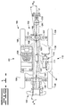
- Fig. 4 is a perspective view of a prime mover, transmission, cooling system, and front and rear drive shafts in accordance with the present invention;
- Fig. 5 is a top view the prime mover, transmission, cooling system, and front and rear drive shafts in accordance with an the present invention;
- Fig. 6. is a section view of the transmission in accordance with the present invention;
- Fig. 7 is a perspective view of the transmission showing the fan drive assembly in accordance with the present invention;
- Fig. 8 is a block diagram of the prime mover, transmission, cooling system, and front and rear drive shafts in accordance with the present invention; and
- Fig. 9 is a hydraulic flow diagram in accordance with the present invention.
-
- While the invention is open to various modifications and alternative forms, a specific embodiment thereof has been shown by way of example in the drawings and will herein be described in detail. There is no intent to limit the invention to the particular form disclosed.
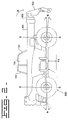
- Referring to Figs. 1-3, a power train arrangement for a
work machine 100, according to an embodiment of the invention, is indicated generally at 90. Thework machine 100 includes a chassis ormain frame 101 having afront end 102 and arear end 103 with a longitudinal axis X-X extending between thefront end 102 and therear end 103 and passing through a longitudinal vertical center plane P of thework machine 100. Themain frame 101 has an elongated configuration defined by first and second substantially parallel and spaced apartside members - Seen specifically in Figs. 1 and 2, the
work machine 100 is a telescopic handler having atelescopic boom 201 that is pivotally connected to themain frame 101 at therear end 103. While the present invention is described with reference to a telescopic handler, other work machines, such as loaders, backhoes, non-telescopic handlers and the like are within the scope of the invention. - An extremity or
distal end 202 of theboom 201 can be fitted with an attachment, such as a pallet lifting fork or the like. For proper balancing of thework machine 100, the longitudinal centerline of theboom 201 lies in the longitudinal vertical center plane P of the work machine. Within this plane P, theboom 201 can be raised and lowered, as well as extended and shortened, by hydraulic cylinders and pistons (not shown), as is well known. As a result of this arrangement, for any given material load, thework machine 100 experiences the greatest moment force M that urges thework machine 100 about itsfront end 102 when theboom 201 is fully extended. Therefore, proper distribution of the work machine's weight along the longitudinal axis X-X is important for maximizing the load carrying capability of thework machine 100 and ensuring that thework machine 100 is stable at maximum carrying loads. - In order to traverse uneven terrain, the
work machine 100 is equipped with large front andrear wheels 106, which are rotatably supported on respective front andrear axles rear axles main frame 101 near the front andrear ends main frame 101, respectively, and extend transversely relative to the longitudinal axis X-X of themain frame 101. The large front andrear wheels 106 limit the available space for other essential components of thework machine 100. Seen specifically in Fig. 2, both the front andrear wheels 106 can be pivotable about a respective vertical steering axis S-S for steering thework machine 100, further limiting the available space in which to arrange other essential components of thework machine 100. - Referring again to Fig. 1, the front and
rear axles rear differentials work machine 100. Afront drive shaft 120 leads to thefront differential 109 for driving that differential. Similarly, arear drive shaft 121 leads to therear differential 110 for driving that differential. As discussed further below, the front andrear drive shafts work machine 100 and may be co-linear with respect to each other. Alternatively, these drive shafts may be angled with respect to the longitudinal vertical center plane P and/or with respect to each other as shown in Fig. 1. In the case where the front andrear drive shafts - Referring to Figs. 1, and 4-5, the
work machine 100 has aprime mover 111, for example a heat engine such as a compression ignition or diesel engine, for generating the required torque to move thework machine 100 as well as power to operate various auxiliary components of thework machine 100, including hydraulics pumps for actuating the hydraulic pistons and cylinders (not shown). According to this embodiment, theprime mover 111 is upright and located to afirst side 112 of themain frame 101. Seen specifically in Fig. 4, the prime mover is preferably fixed to aplatform 137 that is attached to themain frame 101 in any suitable manner, preferably, releasably mounted via a plurality of bolts (not shown). The longitudinal centerline E-E of theprime mover 111 may be set at an angle with respect to the longitudinal axis X-X of themain frame 101, but is preferably parallel to the longitudinal axis X-X as shown in Fig. 5. - Referring to Figs. 1 and 4-6, the
work machine 100 has atransmission 113 for transmitting torque from theprime mover 111 to thewheels 106. As shown in Fig. 4, thetransmission 113 is also preferably fixed to theplatform 137 that is attached to themain frame 101. Thetransmission 113 includes ahousing 114 that houses aninput gear assembly 115 and anoutput gear assembly 116, and may also include anintermediate gear assembly 117, as seen best in Fig. 6. Thehousing 114 is rigidly coupled to theprime mover 111 at one end, for example, the front end of the prime mover as shown in Fig. 5. In the case of an automatic transmission, seen best in Figs. 5-6 and 8, thetransmission 113 includes atorque converter 118 coupled thereto, also disposed within thehousing 114, to provide a fluid coupling between anoutput shaft 119 of theprime mover 111 and theinput gear assembly 115 of thetransmission 113. While the present invention is described with respect to an automatic transmission, other transmissions, such as simple or compound mechanical change-gear transmissions that can be shifted using manual, semiautomatic, or fully automatic actuators to select one of a number of gear ratios between an input shaft and an output shaft of the transmission are within the scope of the present invention. - The
input gear assembly 115 of thetransmission 113 is rotatable in response to rotation of theoutput shaft 119 of theprime mover 111, such as a crankshaft, through thetorque converter 118. Seen specifically in Fig. 6, the rotational axes of the transmission's input, output and intermediate gear assemblies 115-117 are set to be preferably parallel to the rotational axis of theoutput shaft 119 of theprime mover 111, which, in turn, is preferably parallel to the longitudinal axis X-X of themain frame 101. This parallel alignment reduces the complexity of thetransmission 113, since it eliminates the requirement for beveled gears to compensate for any offset angle between thetransmission 113 and theprime mover 111 and/or the front andrear drive shafts input gear assembly 115 may be preferably coaxial with the rotational axis of theoutput shaft 119 of theprime mover 111. Theintermediate gear assembly 117 kinematically couples theinput gear assembly 115 to theoutput gear assembly 116 in a manner that directionally offsets theoutput gear assembly 116 orthogonal from the rotational axis of theinput gear assembly 115. Theintermediate gear assembly 117 includes anidler gear 117a. - As shown in Figs. 1 and 4-6, the
transmission 113 extends laterally to a location where the rotational axis of the transmissionoutput gear assembly 116 lies in or near the longitudinal vertical center plane P of thework machine 100. Thetransmission 113 may also extend vertically downward to a location beneath themain frame 101 so that the rotational axis of the transmissionoutput gear assembly 116 is co-linear, or as near as possible to being co-linear, with the front andrear drive shafts transmission 113, and in particular the transmission'soutput gear assembly 116, are preferably coupled to the front andrear drive shafts rear differentials rear drive shafts output gear assembly 116 and the front and rear drive shafts can be made through respective front andrear yokes transmission output shaft 116c of theoutput gear assembly 116, seen in Fig. 6. Positioning thetransmission 113 at a position equidistant between the front andrear differentials transmission 113 intermediate to theprime mover 111 and an associatedcooling system 122. Therefore, theprime mover 111,transmission 113, andcooling system 122 are serially aligned in that order relative from therear end 103 of thework machine 100. - As seen best in Fig. 4, the
cooling system 122 is associated with theprime mover 111 and is preferably fixed to theplatform 137 that is attached to themain frame 101. Thecooling system 122 includes aheat exchanger 123, such as a radiator, that provides fluid-to-air heat exchange for a coolant that circulates throughout a cooling jacket (not shown) to cool theprime mover 111. Afan 125 is provided on a side of theheat exchanger 123 facing theprime mover 111 to force air across theheat exchanger 123 in a known manner. As will be described below with respect to the work machine's hydraulic system, thecooling system 122 also circulates coolant past a hydraulic fluid heat exchanger (not shown) to cool hydraulic fluid used in thework machine 100. - As mentioned previously, the
transmission 113 is disposed between theprime mover 111 and thecooling system 122. Therefore, as seen best diagrammatically in Fig. 8, one side of the transmission 113 (e.g., the rear side) is kinematically coupled to theprime mover 111 via thetorque converter 118 to drive the front and rear drive shafts 120,121 through the transmission gear assemblies 115,116 and 117. In this manner, theprime mover 111 may be connected and disconnected from the front andrear drive shafts work machine 100 to remain stopped while the engine continues running. Although atorque converter 118 is used, it should be understood that any suitable coupling, such as a friction clutch or the like, may be used to connect theprime mover 111 with thetransmission 113. - Further, the other side of the transmission 113 (e.g., the front side) is coupled to the
fan 125 of thecooling system 122 through adrive fan assembly 126 so that theprime mover 111 drives thefan 125. Seen in Fig. 6, the coupling of the prime mover with thecooling system 122 occurs through a series ofgears 126a andidler gear 117a included in thedrive fan assembly 126 which are disposed within thehousing 114. - As seen in Fig. 7, the
fan drive assembly 126 of thetransmission 113 is shown in more detail without thecooling system 122 in order to improve clarity. To maximize the power transmitted to the differentials 109,110 from theprime mover 111, thefan 125 is mechanically driven directly by afan drive output 127. Preferably, thefan drive output 127 is a pulley rotatably coupled to theprime mover 111 through thetransmission 113 and driven by a fandrive input pulley 128 and abelt 129. Theprime mover 111 and the fandrive input pulley 128 are connected through the series ofgears 126a andidler gear 117a. Also preferably, the rotational axes of thefan drive output 127 andfan drive input 128 are substantially parallel to the rotational axis of theoutput shaft 119 of theprime mover 111. However, it should be understood that the rotational axes of thefan drive output 127 orfan drive input 128 may be coaxial with the rotational axis of theoutput shaft 119 of theprime mover 111. While the present invention is described as a directfan drive assembly 126, other fan mechanisms, such as hydraulic various displacement pump and fluid motor fan drives are within the scope of the present invention. - As described above, the
prime mover 111,transmission 113, andcooling system 122 are preferably mounted on or fixed to theplatform 137, thereby forming a subassembly ormodule 139, seen best in Fig. 4, that can be separately assembled and then secured (e.g., bolted) to themain frame 101. As shown in Fig. 1, themodule 139 may also include a surroundingenclosure 136. - Referring again to Figs. 1-3, an operator's
cabin 130 is mounted to themain frame 101 and located to asecond side 131 of themain frame 101 opposite to thefirst side 112 at which theprime mover 111 is located. The operator'scabin 130 has afront window 132, arear window 133, and twoside windows - Because the
transmission 113 is centered in a longitudinal direction on thework machine 100 and opposes the operator'scabin 130, it is preferable to place thetransmission 113 at a relatively low position on thework machine 100 to avoid interference with the operator'scabin 130. In particular, thework machine 100 must have a minimum ground clearance H1 as shown in Figs. 2 and 3, and the work machine's chassis ormain frame 101 must be sufficiently strong to withstand the loads placed on thework machine 100. Therefore, thetransmission 113 should preferably be placed within the narrow space H2 provided between the minimum ground clearance H1 and abottom portion 138 of themain frame 101 that defines a lower limit of the longitudinally extending gap for theboom 201. To accomplish this arrangement, thetransmission 113 is preferably made relatively flat or with a slightly curved profile as shown in Figs. 4, 6, and 7. Since the output of theprime mover 111 is positioned above thedrive shafts transmission 113 may also be downwardly sloped. Additional gears may be used inside thetransmission housing 114 as required to extend the transmissionoutput gear assembly 116 to thedrive shafts - As shown in the hydraulic flow diagram of Fig. 9, the
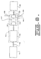
work machine 100 has a common oil system or circuit, generally indicated at 500 that combines both a transmissionlubricating oil system 501 and ahydraulic oil system 502. In particular, the common oil system includes acommon tank 503 that is shared by the transmission lubricatingoil system 501 and thehydraulic oil system 502, a main pump (also referred to as an implement pump) 504 that draws oil from thecommon tank 503 for providing hydraulic pressure to the work machine's actuating pistons and cylinders (not shown), acharge pump 505 the draws oil from thecommon tank 503 and feeds it to thetorque converter 118 and thetransmission 113 and ascavenge pump 506 that draws oil from thetransmission sump 508 and returns it to thecommon tank 503. At some stage in the transmission lubricatingoil system 501, for example after the oil passes through thetorque converter 118, the oil passes through an oil-to-water heat exchanger (not shown) that transfers heat from the lubricating oil to the coolant in thecooling system 122. Furthermore, anoil filter 507 is included, and is preferably placed at the outlet of thecharge pump 505 because of the constant flow of oil, to filter the oil shared by both the transmission lubricatingoil system 501 andhydraulic oil system 502. Accordingly, the transmission lubricatingoil system 501 functions as the filter and cooling circuit for the oil in thecommon tank 503. Furthermore, since thetransmission 113 is positioned between theprime mover 111 andcooling system 122, additional room is created to position the main or implementpump 504 parallel to theprime mover 111, which are conventionally placed in series, thereby enabling a shorterprime mover 111 andtransmission 113. The main or implementpump 504 is driven by ashaft 509, seen best in Fig. 6, that is rotatably coupled to theprime mover 111 through the same series ofgears 126a that couple theprime mover 111 with thecooling system 122. - The
power train arrangement 90, including theprime mover 111,transmission 113, andcooling system 122 are located on one side of awork machine 100, opposite to the operator'scabin 130. Typically, theprime mover 111,transmission 113, andcooling system 122 are preferably fixed to theplatform 137 to form a subassembly ormodule 139. As discussed above, the operator generally has good visibility in all directions, except the direction in which theprime mover 111,transmission 113, andcooling system 122 obstruct the operator's visibility. Accordingly, the operator's visibility can be substantially improved by lowering themodule 139, that is, by lowering theprime mover 111,transmission 113,cooling system 122, and surroundingenclosure 136. - For this reason, the
transmission 113 is made relative flat to fit within the narrow space H2 provided between the minimum ground clearance H1 of thework machine 100 and thebottom portion 138 of themain frame 101 that defines a lower limit of the longitudinally extending gap for theboom 201. The narrow space H2 provided for thetransmission 113 in its sloped configuration restricts the space available for a traditional splash lubricating system, wherein a sufficient level of fluid is maintained in the transmission'ssump 508. To overcome this constraint, thetransmission 113 may be dry-sumped and the lubricating oil pumped to a tank as explained below. Using this dry-sumped configuration, the transmission gear assemblies 115-117 are not retarded due to hydrodynamic drag. Furthermore, a dipstick is not required to ensure that a sufficient level of fluid is maintained within thetransmission sump 508. - A
common oil tank 503 is used to supply oil to both the transmission lubricatingoil system 501 and thehydraulic oil system 502. In order for the transmission lubricatingoil system 501 and thehydraulic oil system 502 to draw oil from thecommon tank 503, thecommon tank 503 must be sufficiently large to provide the required fluid capacity. This is made possible due to the positioning of thetransmission 113 intermediate to theprime mover 111 andcooling system 122, which eliminates the need for a transfer gear case, and allows for the positioning of the main or implementpump 505 parallel to theprime mover 111, increasing spatial capabilities for thepower train arrangement 90. - The present invention
power train arrangement 90 can be used on work machines having different size chassis with little or no alteration to the design of thepower train arrangement 90. Because the lateral distance between the front andrear drive shafts prime mover 111 can vary depending on the size of the work machine, and in particular the width of themain frame 101, the drive shaft angles can vary by several degrees among different size work machines. However, by placing thetransmission 113 between theprime mover 111 and thecooling system 122 so as to substantially center the transmissionoutput gear assembly 116 between the front andrear drive shafts module 139 design can be used for different size work machines, while maintaining acceptable drive shaft angles. This ability results in reduced drive shaft angles f, r, f, r, thereby minimizing vibration and wear to thepower train arrangement 90. In particular, minimizing the drive shaft angles provides added flexibility, since a single power train arrangement that includes the prime mover, transmission, and cooling system can be used for a wider range of work machines and still provide acceptable drive shaft angles. Further, since a plurality of thesame modules 139 can be manufactured and then mounted to different size work machines, significant reductions in manufacturing costs may be achieved. - The
transmission 113 is compactly designed so that thehousing 114 encapsulates all transmission components and is positioned to eliminate the need for a transfer gear case. Furthermore, thetransmission 113 is positioned for connection with theprime mover 111 at the rear side and thefan drive assembly 126 at the front side through the series ofgears 126a. Therefore, thetransmission 113 simultaneously and drivingly connects the front and rear drive shafts 120,121 and thefan 125 to theprime mover 111 through gearing mechanisms within thehousing 114. This ability reduces spatial requirements and connections necessary in typical drive systems wherein the cooling system is directly connected with theprime mover 111. Additionally, the mechanicalfan drive assembly 126 is simple, more efficient, and can be easily configured when coupled to theprime mover 111 through thetransmission 113. - Another advantage of placing the
transmission 113 between theprime mover 111 and thecooling system 122 is that proper distribution of the work machine's weight along the longitudinal axis X-X is obtained to counter the moment force M. The position of theprime mover 111 at a more rearward position than thetransmission 113 andcooling system 122 places the greatest proportion of load (weight) farther away from the front end of thework machine 100 to maximize the load carrying capability of thework machine 100 and ensure that thework machine 100 is more stable at maximum carrying loads. - Other aspects, objects and advantages of the invention can be obtained from a study of the drawings, the disclosure and the appended claims.
Claims (33)
- A power train arrangement (90), comprising:a prime mover (111),a cooling system (122); anda transmission (113) coupled to the prime mover (111) and the cooling system (122), the transmission (113) being positioned intermediate the prime mover (111) and the cooling system (122).
- The power train arrangement (90) according to claim 1, including a platform (137) with the prime mover (111), transmission (113), and cooling system (122) being mounted on the platform (137) to define a module (139).
- The power train arrangement (90) according to claim 1, including front and rear drive shafts (120,121) with the transmission (113) having an input and an output (115,116), the transmission (113) being coupled to the prime mover (111) through the input (115) and the transmission (113) being coupled to the front and rear drive shafts (120,121) through the output (116).
- The power train arrangement (90) according to claim 3, including front and rear yokes (116a,116b) with the transmission output (116) having a transmission output shaft (116c) extending from both a front and rear side of the transmission (113), the front and rear yokes (116a,116b) being connected to the transmission output shaft (116c) on respective front and rear sides of the transmission (113) and the front and rear yokes (116a,116b) being respectively coupled to the front and rear drive shafts (120,121).
- The power train arrangement (90) according to claim 3, wherein the front drive shaft (120) is substantially equal in length to the rear drive shaft (121).
- The power train arrangement (90) according to claim 3, wherein the prime mover (111) has an output shaft (116c) with a rotational axis and the transmission input and output (115,116) each have a rotational axis, the rotational axes of the transmission input (115) and transmission output (116) being substantially parallel with the rotational axis of the prime mover (111).
- The power train arrangement (90) according to claim 3, wherein the prime mover (111) has an output shaft (119) with a rotational axis and the transmission input and output (115,116) each have a rotational axis, the rotational axis of the transmission input (115) being substantially coaxial with the rotational axis of the prime mover (111) and parallel with the rotational axis of the transmission output (116).
- The power train arrangement (90) according to claim 6, wherein the transmission (113) includes a fan drive assembly (126) with a fan drive output (127) having a rotational axis and the cooling system (122) includes a fan (125) driven by the fan drive output (127), the rotational axis of the fan drive output (127) being substantially parallel to the rotational axes of the transmission input (115) and transmission output (116).
- The power train arrangement (90) according to claim 6, wherein the transmission (113) includes a fan drive assembly (126) with a fan drive output (127) having a rotational axis and the cooling system (122) includes a fan (125) driven by the fan drive output (127), the rotational axis of the fan drive output (127) being substantially coaxial with the rotational axis of the transmission input (115).
- The power train arrangement (90) according to claim 6, wherein both the transmission input (115) and transmission output (116) are gear assemblies and the transmission (113) includes an intermediate gear assembly (117) that kinematically couples the input gear assembly (115) to the output gear assembly (116) to offset the output gear assembly (116) in a direction orthogonal to the rotational axis of the input gear assembly (115).
- The power train arrangement (90) according to claim 1, wherein the prime mover (111) has an output shaft (119) with a rotational axis for coupling with the transmission (113), the transmission (113) includes a drive assembly (126) with a drive output (127) having a rotational axis and the cooling system (122) is operatively associated with the drive output (127), the rotational axis of the drive output (127) being substantially parallel to the rotational axis of the output shaft (119) of the prime mover (111).
- The power train arrangement (90) according to claim 11, wherein the drive assembly (126) includes a drive pulley (128) and a belt (129) and the cooling system (122) includes a fan (125), the drive pulley (128) being coupled to the drive output (127) by the belt (129) for directly driving the fan (125) via the drive output (127).
- A work machine (100) having front and rear ends (102,103), comprising:a main frame (101) having first and second sides (112,131);a prime mover (111);a cooling system (122); anda transmission (113) coupled to the prime mover (111) and the cooling system (122), the transmission (113) being positioned intermediate the prime mover (111) and the cooling system (122) with the prime mover (111), the transmission (113), and the cooling system (122) being disposed on the first side (112) of the main frame (101).
- The work machine (100) according to claim 13, wherein the prime mover (111) is disposed rearwardly of the transmission (113) and cooling system (122) relative to the front end (102) of the work machine (100).
- The work machine (100) according to claim 13, including an operator's cabin (130) disposed on the second side (131) of the main frame (101) opposite the first side (112) of the main frame (101).
- The work machine (100) according to claim 13, including a transmission lubricating oil system (501) and a hydraulic oil system (502), and a common tank (503) that supplies oil to both the transmission lubricating oil system (501) and the hydraulic oil system (502).
- The work machine (100) according to claim 16, wherein the oil supplied to both the transmission lubricating oil system (501) and the hydraulic oil system (502) is cooled by exchanging heat with the cooling system (122).
- The work machine (100) according to claim 16, wherein the transmission (113) is dry-sumped and the transmission lubricating oil system (501) includes a charge pump (505) for feeding oil to the transmission (113) and a scavenge pump (506) that draws oil from the transmission (113) and returns the oil drawn from the transmission (113) to the common tank (503).
- The work machine (100) according to claim 16, wherein the hydraulic oil system (502) includes an implement pump (504) disposed parallel with the prime mover (111).
- The work machine (100) according to claim 13, including a platform (137) on which the prime mover (111), the transmission (113), and the cooling system (122) are mounted to form a module (139);
a front wheel and a rear wheel (106);
a front drive shaft (120) for transmitting a first torque to the front wheel (106);
a rear drive shaft (121) for transmitting a second torque to the rear wheel (106); and
the transmission (113) includes an input gear assembly (115) and an output gear assembly (116), the transmission (113) being coupled to the prime mover (111) through the input gear assembly (115) and the transmission (113) being coupled to the front and rear drive shafts (120,121) through the output gear assembly (116). - The work machine (100) according to claim 20, including a front differential and a rear differential (109,110), and wherein the front drive shaft (120) transmits the first torque to the front wheel (106) through the front differential (109) and the rear drive shaft (121) transmits the second torque to the rear wheel (106) through the rear differential (110).
- The work machine (100) according to claim 20, wherein the front drive shaft (120) is substantially equal in length to the rear drive shaft (121).
- The work machine (100) according to claim 20, including front and rear yokes (116a,116b) with the transmission output gear assembly (116) having a transmission output shaft (116c) extending from both a front and rear side of the transmission (113), the front and rear yokes (116a,116b) being connected to the transmission output shaft (116c) on respective front and rear sides of the transmission (113).
- The work machine (100) according to claim 20, wherein the transmission (113) includes a direct fan drive assembly (126) having a drive pulley (128), a fan drive output (127) with a rotational axis, and a belt (129) that couples the drive pulley (128) to the fan drive output (127) and the cooling system (122) includes a fan (125) that is driven by the fan drive output (127), the rotational axis of the fan drive output (127) is substantially parallel to the rotational axis of the output shaft (119) of the prime mover (111).
- The work machine (100) according to claim 20, wherein the prime mover (111) has an output shaft (119) with a rotational axis, the input gear assembly (115) has a rotational axis and the output gear assembly (116) has a rotational axis, the rotational axes of the input and output gear assemblies (115,116) being substantially parallel with the rotational axis of the prime mover (111).
- The work machine (100) according to claim 25, wherein the transmission (113) includes an intermediate gear assembly (117) that kinematically couples the input gear assembly (115) to the output gear assembly (116) and that offsets the output gear assembly (116) in a direction orthogonal to the rotational axis of the input gear assembly (115).
- The work machine (100) according to claim 20, wherein the transmission (113) includes a torque converter (118), and wherein the input gear assembly (115) is coupled to the prime mover (111) through the torque converter (118).
- The work machine (100) according to claim 27, including a common housing (114) that encloses the torque converter (118), input gear assembly (115) and output gear assembly (116) of the transmission (113).
- The work machine (100) according to claim 13, wherein the work machine (100) is a telescopic material handler including:two front wheels (106) disposed on opposite sides of the main frame (101);two rear wheels (106) disposed on opposite sides of the main frame (101);a front drive shaft (120) for transmitting a first torque to at least one of the two front wheels (106);a rear drive shaft (121) for transmitting a second torque to at least one of the two rear wheels (106);an operator's cabin (130) disposed on a second side (131) of the main frame (101) opposite a first side (112) of the main frame (101);a telescopic boom (201) centrally disposed between the operator's cabin (130) on the second side (131) of the main frame (101) and the prime mover (111), the transmission (113), and the cooling system (122) on the first side (112) of the main frame (101), the telescopic boom (201) pivotally connected at a rear end (103) of the main frame (101) and having a distal end (202) extending past a front end (102) of the main frame (101), the telescopic boom (201) adapted to carry a load at its distal end (202); andinput and output gear assemblies (115,116) disposed within the transmission (113), the transmission (113) being coupled to the prime mover (111) through the input gear assembly (115) and the front and rear drive shafts (120,121) being coupled to the transmission (113) through the output gear assembly (116) so that the prime mover (111) is distanced farther from the distal end (202) of the telescopic boom (201) than the transmission (113) and cooling system (122).
- The work machine (110) according to claim 29, wherein the transmission (113) is positioned within a space (H2) defined at a bottom portion of the main frame (101) above a minimum ground clearance (H1).
- A work machine (100) having front and rear ends (102,103), comprising:a main frame (101);a platform (137);a prime mover (111), transmission (113) and cooling system (122) connected to the platform (137) to define a module (139) releasably connected to the main frame (101), the prime mover (111), transmission (113) and cooling system (122) being interconnected so that the prime mover (111) is positioned rearwardly from the transmission (113) and cooling system (122) in relation to the front end (102) of the work machine (100);a front wheel and a rear wheel (106);a front drive shaft (120) coupled to the transmission (113) for transmitting a first torque to the front wheel (106), the front drive shaft (120) having a predetermined length; anda rear drive shaft (121) coupled to the transmission (113) for transmitting a second torque to the rear wheel (106), the rear drive shaft (121) having a predetermined length equal to the predetermined length of the front drive shaft (120).
- The work machine (100) according to claim 31, wherein the transmission (113) has front and rear sides and the interconnection between the prime mover (111), transmission (113) and cooling system (122) includes that the transmission (113) is coupled at the front side to the cooling system (122) and is coupled at the rear side to the prime mover (111) with the transmission (113) positioned between the prime mover (111) and the cooling system (122).
- A method of manufacturing a plurality of work machines (100), including a first work machine (100) having a first main frame (101) and a second work machine (100') having a second main frame (101'), wherein the second main frame (101') is larger than the first main frame (101), comprising the steps of:providing two prime movers (111), two transmissions (113), two cooling systems (122), and two platforms (137);assembling a first module (139) and a second module (139'), each of the first and second modules (139,139') including one of the two prime movers (111), one of the two transmissions (113), and one of the two cooling systems (122) mounted to a respective one of the two platforms (137), wherein for each of the first and second modules (139,139') the transmission (113) is coupled to the respective prime mover (111) and the respective cooling system (122) is coupled to the transmission (113) with the transmission (113) being disposed intermediate to the prime mover (111) and the cooling system (122); andmounting the first module (139) to the first main frame (101) and mounting the second module (139') to the second main frame (101').
Applications Claiming Priority (4)
| Application Number | Priority Date | Filing Date | Title |
|---|---|---|---|
| US33284501P | 2001-11-16 | 2001-11-16 | |
| US332845P | 2001-11-16 | ||
| US101668 | 2002-03-19 | ||
| US10/101,668 US6904994B2 (en) | 2001-11-16 | 2002-03-19 | Horizontal transmission and oil system for telehandlers |
Publications (3)
| Publication Number | Publication Date |
|---|---|
| EP1312498A2 true EP1312498A2 (en) | 2003-05-21 |
| EP1312498A3 EP1312498A3 (en) | 2004-05-26 |
| EP1312498B1 EP1312498B1 (en) | 2007-11-21 |
Family
ID=26798502
Family Applications (1)
| Application Number | Title | Priority Date | Filing Date |
|---|---|---|---|
| EP02020301A Expired - Lifetime EP1312498B1 (en) | 2001-11-16 | 2002-09-11 | Horizontal transmission and oil system for telehandlers |
Country Status (3)
| Country | Link |
|---|---|
| US (1) | US6904994B2 (en) |
| EP (1) | EP1312498B1 (en) |
| DE (1) | DE60223643T2 (en) |
Cited By (2)
| Publication number | Priority date | Publication date | Assignee | Title |
|---|---|---|---|---|
| EP1987978A2 (en) | 2007-05-04 | 2008-11-05 | Dana Heavy Vehicle Systems Group, LLC | Transmission system for a vehicle |
| US9669709B2 (en) | 2014-09-23 | 2017-06-06 | Zf Friedrichshafen Ag | Drive train for a vehicle |
Families Citing this family (9)
| Publication number | Priority date | Publication date | Assignee | Title |
|---|---|---|---|---|
| US8365637B2 (en) * | 2007-10-23 | 2013-02-05 | Caterpillar Inc. | Drop box for powertrain |
| US8057138B2 (en) * | 2009-07-17 | 2011-11-15 | International Truck Intellectual Property Company, Llc | Stackable armored vehicle |
| ITTO20100310A1 (en) * | 2010-04-16 | 2011-10-17 | Movimatica Srl | ELECTRIC HYDRAULIC HYDRAULIC LIFT VEHICLE |
| JP6080630B2 (en) * | 2013-03-19 | 2017-02-15 | 株式会社タダノ | Work vehicle |
| DE102014219103A1 (en) * | 2014-09-23 | 2016-03-24 | Zf Friedrichshafen Ag | mobile vehicle |
| FI127328B (en) * | 2015-06-10 | 2018-03-29 | Sks Toijala Works Oy | Arrangement for mounting energy device on mobile telescopic loaders |
| DE102017007552A1 (en) * | 2016-10-25 | 2018-04-26 | Neander Motors Ag | Drive unit for a motor vehicle |
| DE102018002464A1 (en) * | 2018-03-26 | 2019-09-26 | Neander Motors Aktiengesellschaft | Motor vehicle with four-wheel drive |
| DE102019205987B4 (en) * | 2019-04-26 | 2022-05-05 | Zf Friedrichshafen Ag | Electric axle drive for a vehicle |
Citations (2)
| Publication number | Priority date | Publication date | Assignee | Title |
|---|---|---|---|---|
| US6105710A (en) | 1998-04-11 | 2000-08-22 | Clark Equipment Beigium N.V. | Transmission for a vehicle having a motor arranged outside its longitudinal center plane |
| US6152253A (en) | 1998-04-28 | 2000-11-28 | Gehl Company | Drive train system for a construction-type vehicle |
Family Cites Families (27)
| Publication number | Priority date | Publication date | Assignee | Title |
|---|---|---|---|---|
| US2871724A (en) | 1954-02-25 | 1959-02-03 | Clark Equipment Co | Vehicle drive means |
| GB976049A (en) | 1962-03-22 | 1964-11-25 | Maschf Augsburg Nuernberg Ag | Improvements in and relating to power-driven vehicles |
| US3331464A (en) | 1965-01-08 | 1967-07-18 | Doorne S Automobielfabriek N V | Four wheel belt variable transmission drive |
| US3677358A (en) * | 1971-04-16 | 1972-07-18 | Int Harvester Co | Drive train for low profile vehicle |
| US3865205A (en) * | 1971-11-11 | 1975-02-11 | Clark Equipment Co | Two wheel tractor |
| JPS4948304U (en) * | 1972-07-28 | 1974-04-27 | ||
| US3894603A (en) * | 1972-08-29 | 1975-07-15 | Caterpillar Tractor Co | Vehicle drive train |
| FR2340850A1 (en) * | 1976-02-10 | 1977-09-09 | Bidon Jacques | TRACTOR VEHICLE, ESPECIALLY FOR AGRICULTURAL USE |
| US4274505A (en) * | 1978-09-18 | 1981-06-23 | Maust Gale E | Hydrostatic-drive tractor |
| US4484656A (en) * | 1982-05-19 | 1984-11-27 | Industrial Vehicles International, Inc. | Carrier vehicle for seismic vibrational system |
| JPS61166729A (en) | 1985-01-16 | 1986-07-28 | Toyota Motor Corp | Power transmission device for four-wheel drive vehicle |
| US4805720A (en) | 1986-02-27 | 1989-02-21 | Clenet Alain J M | Vehicle drivetrain |
| US5024287A (en) * | 1987-03-31 | 1991-06-18 | Yamaha Hatsudiki Kabushiki Kaisha | Engine unit for vehicle |
| US5120187A (en) | 1990-12-10 | 1992-06-09 | Weber Murray S | Power control assembly for vehicle having power tool attachment |
| GB2292931B (en) | 1992-06-30 | 1996-10-02 | Caterpillar Inc | Material handling machine |
| FR2713155B1 (en) | 1993-12-01 | 1996-01-26 | Manitou Bf | Forklift with telescopic arm. |
| GB9408790D0 (en) | 1994-05-04 | 1994-06-22 | Caterpillar Inc | Work vehicle |
| EP0692448A1 (en) | 1994-07-15 | 1996-01-17 | J.C. Bamford Excavators Limited | Material-handling vehicle |
| WO1998032928A1 (en) | 1997-01-28 | 1998-07-30 | Manitou Bf S.A. | Improvements to tractor shovels |
| US5931255A (en) | 1997-05-09 | 1999-08-03 | Caterpillar Inc. | Power transfer arrangement for a machine |
| GB2336255B (en) * | 1998-04-08 | 2002-03-13 | Gen Domestic Appliances Ltd | Cooking appliance energy regulator |
| GB9807532D0 (en) * | 1998-04-09 | 1998-06-10 | Bamford Excavators Ltd | Material-handling vehicle |
| GB9807538D0 (en) | 1998-04-09 | 1998-06-10 | Bamford Excavators Ltd | Material-handling vehicle |
| US6098739A (en) * | 1998-06-05 | 2000-08-08 | Caterpillar S.A.R.L. | Main frame assembly |
| EP1028020A3 (en) | 1999-02-09 | 2003-03-26 | Tecumseh Products Company | Hydrostatic transmission having two-piece pump and motor block assembly |
| US6793028B2 (en) | 1999-05-11 | 2004-09-21 | Caterpillar S.A.R.L. | Mounting arrangement for a radiator assembly of a work machine |
| GB9921800D0 (en) | 1999-09-16 | 1999-11-17 | Bamford Excavators Ltd | Material -handling vehicle |
-
2002
- 2002-03-19 US US10/101,668 patent/US6904994B2/en not_active Expired - Lifetime
- 2002-09-11 DE DE60223643T patent/DE60223643T2/en not_active Expired - Lifetime
- 2002-09-11 EP EP02020301A patent/EP1312498B1/en not_active Expired - Lifetime
Patent Citations (2)
| Publication number | Priority date | Publication date | Assignee | Title |
|---|---|---|---|---|
| US6105710A (en) | 1998-04-11 | 2000-08-22 | Clark Equipment Beigium N.V. | Transmission for a vehicle having a motor arranged outside its longitudinal center plane |
| US6152253A (en) | 1998-04-28 | 2000-11-28 | Gehl Company | Drive train system for a construction-type vehicle |
Cited By (2)
| Publication number | Priority date | Publication date | Assignee | Title |
|---|---|---|---|---|
| EP1987978A2 (en) | 2007-05-04 | 2008-11-05 | Dana Heavy Vehicle Systems Group, LLC | Transmission system for a vehicle |
| US9669709B2 (en) | 2014-09-23 | 2017-06-06 | Zf Friedrichshafen Ag | Drive train for a vehicle |
Also Published As
| Publication number | Publication date |
|---|---|
| US20030094325A1 (en) | 2003-05-22 |
| DE60223643D1 (en) | 2008-01-03 |
| US6904994B2 (en) | 2005-06-14 |
| EP1312498A3 (en) | 2004-05-26 |
| DE60223643T2 (en) | 2008-10-30 |
| EP1312498B1 (en) | 2007-11-21 |
Similar Documents
| Publication | Publication Date | Title |
|---|---|---|
| CN105569102B (en) | Working machine | |
| US6904994B2 (en) | Horizontal transmission and oil system for telehandlers | |
| US7980339B2 (en) | Power transmission system of hydraulically driven working vehicle | |
| EP0692448A1 (en) | Material-handling vehicle | |
| US6902026B2 (en) | Wheel type traveling and operating vehicle | |
| US9534615B1 (en) | Hydraulic pump and motor module for use in a vehicle | |
| US6994180B1 (en) | Utility vehicle having hydrostatic drive | |
| US6990759B2 (en) | Material handling vehicle transmission | |
| EP0876932A2 (en) | Power transfer arrangement for a machine | |
| US7228685B2 (en) | Axle driving apparatus | |
| EP0707679B1 (en) | Material handling machine | |
| EP0949185B1 (en) | Material-handling vehicle | |
| US12162346B2 (en) | Working vehicle | |
| EP0945396A2 (en) | A vehicle with a lifting boom, having an engine inclined with respect to the longitudinal axis of the vehicle | |
| EP0949186A2 (en) | Material-handling vehicle | |
| JP4073587B2 (en) | Mobile farm machine | |
| CN218343265U (en) | Power transmission system and engineering machinery | |
| US20230417313A1 (en) | Work vehicle | |
| JPS646724B2 (en) | ||
| JP2001260932A (en) | Crawler traveling vehicle | |
| JP2001253361A (en) | Crawler traveling vehicle | |
| JP3480993B2 (en) | Power transmission structure of agricultural tractor | |
| JP2001260933A (en) | Crawler traveling vehicle | |
| JP2001260934A (en) | Crawler traveling vehicle | |
| JPH04112118U (en) | combine gearing |
Legal Events
| Date | Code | Title | Description |
|---|---|---|---|
| PUAI | Public reference made under article 153(3) epc to a published international application that has entered the european phase |
Free format text: ORIGINAL CODE: 0009012 |
|
| AK | Designated contracting states |
Designated state(s): AT BE BG CH CY CZ DE DK EE ES FI FR GB GR IE IT LI LU MC NL PT SE SK TR |
|
| AX | Request for extension of the european patent |
Extension state: AL LT LV MK RO SI |
|
| PUAL | Search report despatched |
Free format text: ORIGINAL CODE: 0009013 |
|
| AK | Designated contracting states |
Kind code of ref document: A3 Designated state(s): AT BE BG CH CY CZ DE DK EE ES FI FR GB GR IE IT LI LU MC NL PT SE SK TR |
|
| AX | Request for extension of the european patent |
Extension state: AL LT LV MK RO SI |
|
| RIC1 | Information provided on ipc code assigned before grant |
Ipc: 7B 60K 17/34 A Ipc: 7B 60K 5/02 B Ipc: 7B 60K 11/02 B |
|
| 17P | Request for examination filed |
Effective date: 20041125 |
|
| AKX | Designation fees paid |
Designated state(s): DE FR GB IT |
|
| RAP1 | Party data changed (applicant data changed or rights of an application transferred) |
Owner name: CATERPILLAR S.A.R.L. |
|
| RAP1 | Party data changed (applicant data changed or rights of an application transferred) |
Owner name: JLG INDUSTRIES, INC. |
|
| 17Q | First examination report despatched |
Effective date: 20060814 |
|
| GRAP | Despatch of communication of intention to grant a patent |
Free format text: ORIGINAL CODE: EPIDOSNIGR1 |
|
| GRAS | Grant fee paid |
Free format text: ORIGINAL CODE: EPIDOSNIGR3 |
|
| GRAA | (expected) grant |
Free format text: ORIGINAL CODE: 0009210 |
|
| AK | Designated contracting states |
Kind code of ref document: B1 Designated state(s): DE FR GB IT |
|
| REG | Reference to a national code |
Ref country code: GB Ref legal event code: FG4D |
|
| REF | Corresponds to: |
Ref document number: 60223643 Country of ref document: DE Date of ref document: 20080103 Kind code of ref document: P |
|
| ET | Fr: translation filed | ||
| PLBE | No opposition filed within time limit |
Free format text: ORIGINAL CODE: 0009261 |
|
| STAA | Information on the status of an ep patent application or granted ep patent |
Free format text: STATUS: NO OPPOSITION FILED WITHIN TIME LIMIT |
|
| 26N | No opposition filed |
Effective date: 20080822 |
|
| REG | Reference to a national code |
Ref country code: FR Ref legal event code: PLFP Year of fee payment: 15 |
|
| REG | Reference to a national code |
Ref country code: FR Ref legal event code: PLFP Year of fee payment: 16 |
|
| REG | Reference to a national code |
Ref country code: FR Ref legal event code: PLFP Year of fee payment: 17 |
|
| PGFP | Annual fee paid to national office [announced via postgrant information from national office to epo] |
Ref country code: FR Payment date: 20210921 Year of fee payment: 20 Ref country code: IT Payment date: 20210922 Year of fee payment: 20 |
|
| PGFP | Annual fee paid to national office [announced via postgrant information from national office to epo] |
Ref country code: GB Payment date: 20210920 Year of fee payment: 20 Ref country code: DE Payment date: 20210920 Year of fee payment: 20 |
|
| REG | Reference to a national code |
Ref country code: DE Ref legal event code: R071 Ref document number: 60223643 Country of ref document: DE |
|
| REG | Reference to a national code |
Ref country code: GB Ref legal event code: PE20 Expiry date: 20220910 |
|
| PG25 | Lapsed in a contracting state [announced via postgrant information from national office to epo] |
Ref country code: GB Free format text: LAPSE BECAUSE OF EXPIRATION OF PROTECTION Effective date: 20220910 |
|
| P01 | Opt-out of the competence of the unified patent court (upc) registered |
Effective date: 20230507 |