EP1312290A2 - Schalter für Wasserkocher - Google Patents
Schalter für Wasserkocher Download PDFInfo
- Publication number
- EP1312290A2 EP1312290A2 EP02257774A EP02257774A EP1312290A2 EP 1312290 A2 EP1312290 A2 EP 1312290A2 EP 02257774 A EP02257774 A EP 02257774A EP 02257774 A EP02257774 A EP 02257774A EP 1312290 A2 EP1312290 A2 EP 1312290A2
- Authority
- EP
- European Patent Office
- Prior art keywords
- steam
- main body
- switch
- responsive
- contact pair
- Prior art date
- Legal status (The legal status is an assumption and is not a legal conclusion. Google has not performed a legal analysis and makes no representation as to the accuracy of the status listed.)
- Granted
Links
Images

Classifications
-
- A—HUMAN NECESSITIES
- A47—FURNITURE; DOMESTIC ARTICLES OR APPLIANCES; COFFEE MILLS; SPICE MILLS; SUCTION CLEANERS IN GENERAL
- A47J—KITCHEN EQUIPMENT; COFFEE MILLS; SPICE MILLS; APPARATUS FOR MAKING BEVERAGES
- A47J27/00—Cooking-vessels
- A47J27/21—Water-boiling vessels, e.g. kettles
- A47J27/21008—Water-boiling vessels, e.g. kettles electrically heated
- A47J27/21058—Control devices to avoid overheating, i.e. "dry" boiling, or to detect boiling of the water
- A47J27/21108—Control devices to avoid overheating, i.e. "dry" boiling, or to detect boiling of the water using a bimetallic element
-
- A—HUMAN NECESSITIES
- A47—FURNITURE; DOMESTIC ARTICLES OR APPLIANCES; COFFEE MILLS; SPICE MILLS; SUCTION CLEANERS IN GENERAL
- A47J—KITCHEN EQUIPMENT; COFFEE MILLS; SPICE MILLS; APPARATUS FOR MAKING BEVERAGES
- A47J27/00—Cooking-vessels
- A47J27/21—Water-boiling vessels, e.g. kettles
- A47J27/21008—Water-boiling vessels, e.g. kettles electrically heated
- A47J27/21058—Control devices to avoid overheating, i.e. "dry" boiling, or to detect boiling of the water
- A47J27/21066—Details concerning the mounting thereof in or on the water boiling vessel
- A47J27/21075—Details concerning the mounting thereof in or on the water boiling vessel relating to the boiling sensor or to the channels conducting the steam thereto
Definitions
- the present invention relates to a control for use in electrical water boiling appliances and in particular for electric kettles and jugs.
- Electric kettles require a control to allow a user to heat water to a predetermined temperature, usually to boiling, at which point the kettle automatically switches off.
- switches are integrated with additional operative parts having other functions in the kettle, such as thermal limiters that protect the kettle against switching on without water and after some structural arrangement allowing cordless connection.
- the present invention concerns only "stand-alone" switches which have the function of automatically switching off the kettle in response to steam, so-called automatic steam switches of the mechanical-thermal type.
- the switch reacts promptly to steam generation, and that the switch can be rapidly reset even shortly after switching off, and these requirements influence the arrangement of the sensing element.
- the size of the switch is also often of importance, the more compact the switch, the greater the freedom of the designer to create an aesthetically pleasing design which is not dictated by the size or shape of the functional components. However, as the size of the switch is reduced it then becomes increasingly difficult to meet the safety and operational requirements mentioned above.
- a further arrangement is disclosed in GB 2213646 of Strix embodied in their R40 switch where the switch defines a shallow steam enclosure housing a dished bimetallic actuator which acts through a pushrod on a trip lever which in turn breaks contacts in a separate enclosure defined laterally adjacent the steam enclosure.
- the steam enclosure is here provided with an upper vent for the egress of steam. Although facilitate the cooling of the sensing element to allow rapid re-setting, the vent constitutes a source of dangerously hot steam with a risk of injury to a user.
- the present invention is directed to providing a switch which is of improved compactness and yet which provides an excellent thermal response whilst being safe and reliable.
- the steam-responsive switch is preferably a bimetallic element of dished shape which inverts above said predetermined temperature, and which may have a cut-out region therein which defines a tongue-shaped portion which engages said actuating member.
- the bimetallic element is preferably disposed so that the tongue-shaped portion extends towards said steam egress vent, and with the major part of the cut-out region lying on the side of the bimetal nearest the vent. The arrangement of the vent and cut-out region contribute to increased steam flow through the cut-out into the chamber onto the rear of the bimetallic element enhancing the thermal response.
- the actuating member may comprise a pushrod which extends through an opening in said main body and wherein a resilient bellows-type seal is provided between the pushrod and the main body to prevent steam or water from entering said opening.
- the pushrod engages a bistable over-centre lever having an actuating portion which engages the electrical contact pair.
- the switch main body is preferably of short generally cylindrical form, with the tubular portion of circular section.
- Switch sealing means which may be an O-ring, is preferably provided extending circumferentially about the tubular portion of the switch body close to the main body portion. This ensures that a simple push-fit of the switch into a simple cylindrical opening provides steam and water-tight separation of the "wet" steam exposed side of the switch from the opposite "dry” side.
- a cover part is provided to fit over the main body enclosing said electrical contacts therein and having openings to allow electrical connection to said contacts and through which a portion of said lever extends, said openings being surrounded by upstanding water-shedding collars.
- the cover part being of greater outer dimension than the tubular portion forms a shoulder therewith, so that the switch is of plug-like overall form.
- the invention provides a steam-responsive switch for a water boiling appliance comprising a forwardly-facing tubular portion of circular section having a heat responsive member arranged to extend across the forwardly-facing open mouth thereof and a rear portion supporting an electrical contact pair having a movable contact, a movable actuating member being provided which extends from the heat responsive member to the rear portion to act on the contact pair, the rear portion being of outer dimension slightly greater than the tubular portion with a shoulder therebetween whereby the switch has a plug-like shape for making a push-fit within a cylindrical opening or recess in an appliance.
- the rear portion comprises a main body portion from which protrudes said tubular portion and a cover which fits over the main body portion defining said shoulder.
- the main body portion supports said contact pair on a rear face thereof, the movable actuating member extending through the main body in a sealed manner to act on the contact pair.
- the ability to make a simple plug fit into a cylindrical opening or recess on the kettle body is highly advantageous in that it allows a simple regular shape to be provided which is easy to design and manufacture and can be applied to various different kettle designs, and secondly the switch can be easily sealed with respect to the opening, ensuring steam and water-tight separation of the "wet" and “dry” sides of the switch.
- a steam-responsive switch for use in an electrical water boiling appliance comprising a main body from which extends a tubular portion having at or near its leading end a heat responsive member extending across the mouth thereof which changes shape above a predetermined temperature defining a chamber behind the member and at the opposite face of the main body an electrical contact pair, the heat responsive member engaging a slidable actuating member which extends through the main body to act on the electrical contact pair, and a flexible bellows-type seal provided between the actuating member and the main body through which the actuating member extends.
- the main body is provided with a circular groove into which a tubular end of the seal is received.
- the actuating member is a push rod having an enlarged head portion which the heat-responsive member abuts.
- the invention resides in an electrical water boiling appliance with a steam-responsive switch, the appliance having a main water carrying body provided with a steam port at an upper region of the body and an opening or recess defined on the body or a housing part joined thereto which communicates with the steam port, the switch having a main switch body from which extends a tubular portion fitted into said opening or recess having at or near its leading end a heat responsive member extending across the mouth thereof which changes shape above a predetermined temperature defining a chamber behind the member, with an electrical contact pair disposed at the opposite face of the main switch body, a slidable actuating member which engages the heat responsive member extending through the main switch body in a sealed manner to act on the electrical contact pair, the tubular portion having a vent at one side thereof adjacent the rear face of the heat responsive member opening into the chamber for the egress of steam and the ingress of cool air.
- the switch vent is preferably disposed at the lower side of the tubular portion, with the appliance body or housing connected thereto having a passageway in communication with the vent and with the exterior to allow the rapid ingress of cool air after switch-off.
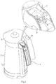
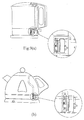
- FIG. 1 shows a water boiling appliance, in this case being a kettle 2 but which could equally be some other kind of water boiling appliance in which a steam-sensing switch is provided.
- the kettle 2 has a main water-carrying body 4 which houses an electrical heating element in the base thereof and a lid 6.
- a handle 8 is joined to the body 4.
- a steam-sensing switch 10 Disposed on the body 4 within an upper portion of the handle 8 is a steam-sensing switch 10 which serves to automatically break the electrical circuit supplying power to the heating element.
- the switch 10 is of generally cylindrical plug-like form whereby it can be fitted into a tubular or cylindrical housing or formation of circular section within the kettle as discussed in further detail below.
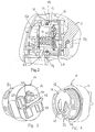
- the switch 10 has a generally shallow cup-like main body 12 having a base region on which the majority of the operative components are supported, and a forwardly-protruding tubular portion 13 defining an interior chamber, and constituting the steam-facing "wet" side of the switch.
- a bimetallic disc 16 secured at its edges on the end of the tubular portion 13 across the mouth thereof so as to be in generally a vertical orientation within the kettle and with its active face facing forwardly to the mouth of the tubular portion 13.
- the bimetallic disc is of conventional dished construction having central U-shaped cut-out defining a tongue 18 which in the cold condition of the switch lies in a forward position and which on reaching a predetermined switching temperature snaps to a more rearward position (to the right in Figure 2) as the direction of dishing of the disc inverts.
- the bimetallic disc may be of a type which on cooling below a second lower predetermined temperature (typically 30°C below its hot switching temperature) automatically snaps back to its original cold condition.
- a second lower predetermined temperature typically 30°C below its hot switching temperature
- it may be of type where it is necessary to manually reset in the manner discussed below.
- the tongue 18 of the bimetallic disc 16 acts on an actuating pushrod 20 which has an enlarged head 22 and at its opposite end is slidably supported in an aperture 24 in the main switch body 12.
- a bellows-type seal member 26 formed of a flexible plastics material such a silicone is disposed about the pushrod 20 between its head 22 and a circular groove defined in the main body 12 about the aperture 24 in which a tubular end of the seal member 26 sits in order to prevent any water which might reach the chamber from passing through the aperture to the opposite "dry" side of the switch, which might otherwise occur along the sides of pushrod 20, for example through capillary action.
- the forward end of pushrod 20 engages a trip lever 28 which is mounted on the rear "dry" side of the main body 12 and pivotably supported at its lower (i.e. in the fitted orientation for example as shown in Figure 2) end.
- a "C” spring 30 is arranged between an indented shoulder on the lever 28 and a downwardly facing indent on a protrusion 32 extending from the main body 12, and is in compression such that the lever constitutes a bi-stable mechanism having an ON position in which the upper end of the lever 28 lies against the main body 12, and an OFF position in which the upper end of the lever 28 is spaced from the main body.
- the lever 28 is formed with a finger 34 extending parallel to the axis of pivoting.
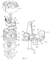
- the electrical components of the switch comprise a switch contact pair including a fixed contact strip 36 with a silver contact 38 and bent at one end to form a spade terminal 40 and a bent movable contact 42 having a silver contact 44 and at the opposite end a spade terminal 46. These contacts are connected electrically in series with the electrical heating element.
- the finger 34 of the lever 28 lies beneath the movable contact 42 such that in the ON position of the lever the contacts touch and power is supplied to the heating element.
- the finger 34 lifts the movable contact 42, the silver contacts 38 and 44 are separated and the electrical connection thereby broken.
- the pushrod 20 is disposed so that its head 22 is spaced from the end of the tongue of the bimetallic disc 16. This is in contrast to the conventional arrangements using such bimetallic discs where the end of the tongue is generally used in order to provide maximum travel.
- the axis of the pushrod 20 is displaced so that the pushrod 20 can effectively act on the lever 28 at a position sufficiently displaced from its lower point, despite the very small size of the lever 28. It is found that despite the decrease in travel of the region of the tongue 18 spaced from its end, the increase in force supplied from this position is able to mitigate any problems of the pushrod movement being insufficient to drive the lever and to compress the bellows seal 26.
- the lever 28 is also formed with a rearwardly-extending protrusion 48 having a T-bar 50 at its end.
- An actuating knob 53 of the kettle for the user to control the switch is slidably mounted on the handle 8 and is connected through web 55 to a lower forked end 54 which fits over the T-bar 50 whereby the user can manually re-set the trip lever 28 to an ON condition.
- the protrusion 48 When assembled with the cover 14 fitted, the protrusion 48 extends through an opening in the cover 14 with the T-bar 50 outside the cover 14 as seen in Figure 3. It will be appreciated however that a variety of alternative means could be utilised to provide a mechanical linkage between the lever 28 and an actuating knob 53.
- the switch When the switch has tripped to the OFF position following boiling and the user wishes to promptly re-set without waiting for the switch to re-cool to a temperature below the second temperature at which the bimetallic element would automatically switch to its lower temperature position, the user can re-set the switch manually using the knob 53 which acts through the lever and pushrod 20 on the bimetallic disc 16 to invert it to its cold condition.
- the design of the switch is arranged to facilitate such rapid re-setting as discussed later.
- the switch 10 is mounted in the mouth of a tubular or cylindrical formation 52 of circular section which is part of or joined to the kettle body with an appropriate port and/or ducting provided to direct steam from the kettle interior onto the "wet" side of the switch 10.
- a port 57 provides direct communication with the kettle interior.
- the tubular portion 13 of the main body makes a plug-fit within the tubular formation 52.
- An O-ring seal 59 seated in a recess 56 on the tubular portion 13 near the base of the main body 12 provides fluid-tight sealing between the portion 13 of the main body 12 and the formation 52 of the kettle and thereby seals the "wet" side of the switch (which as well as being subject to steam is also possibly subject to water in an overfilling or tilted condition) from the opposite "dry" side.
- short collar-like projections 47, 49 on the cover 14 surround openings in the cover for making connection to the spade terminals 40, 46.
- the cover 14 includes a shelf 58 extending laterally across the cover 14 providing additional protection against any water which might inadvertently find its way onto the cover from above from reaching the electrical contacts.
- the opening for the protrusion 48 is likewise provided with a short upstanding collar or edge 60 as a further precaution against spilled water.
- the forward "wet" side of the switch is provided with an opening in the wall of the tubular portion 13 which serves to enhance the cooling of the bimetallic disc 16 after switching in order to allow rapid re-setting. More specifically, the tubular portion 13 is provided with a lower part-circumferentially extending slot-like vent 64.
- the steam On the boiling of water the steam reaches the mouth of the tubular portion and forward face of the bimetallic disc 16 impinging directly onto its forward face from either an axial or radial direction, depending on the kettle design.
- the steam is directed onto the "heart" of the bimetallic disc 16 near the base of the tongue, which is the most active sensing region thereof.
- the steam passes through the U-shaped central opening into the interior chamber, and passes downwardly through the lower opening 64 and through a lower vent 65 in the formation 52.
- the hot air/steam in the kettle body interior rises though the kettle spout creating an updraft, and pulling hot air/steam from the switch and causing a reversed upward movement of air through the lower vent 64 (which may communicate with the exterior environment for example through a duct and opening in the lower end of the handle).
- the lower vent 64 which may communicate with the exterior environment for example through a duct and opening in the lower end of the handle.
- cool air passes into the interior chamber and through the bimetallic disc 16 via the cut-out. In this way the speed of cooling of the bimetallic disc can be maximised, reducing the time for re-setting.
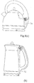
- the switch is mounted within the kettle base and communicates with the kettle interior via a longer steam duct which, as can be better seen in the enlarged views, open into the switch receiving recess in a direction parallel to the face of the bimetallic disc. On boiling, the steam is thereby directed laterally across the face of the bimetallic disc.
- FIGs 8(a) and (b) show two arrangements where the switch is located in a kettle communicating with the interior by appropriate ducting, and where steam impinges directly onto the bimetallic disc.
- ducting 70 is provided to connect the lower switch vent 64 with the base of the handle, whereas in Figure 8(b) the vent 64 communicates with the exterior through a hollow housing interior 72 which is open at its lower edge.
- the described structure provides a switch which can be constructed of very small dimension, for example to a diameter of 27mm, thereby allowing the designer of the aesthetic aspects of the kettle increased design freedom.
- the switch is moreover of rapid response, both on switching off, and allowing rapid re-setting, whilst being of very safe and still simple construction.
Landscapes
- Engineering & Computer Science (AREA)
- Food Science & Technology (AREA)
- Cookers (AREA)
- Thermally Actuated Switches (AREA)
Applications Claiming Priority (2)
| Application Number | Priority Date | Filing Date | Title |
|---|---|---|---|
| GB0127563 | 2001-11-16 | ||
| GB0127563A GB2382225C (en) | 2001-11-16 | 2001-11-16 | Switch for water boiling appliance such as a kettle |
Publications (3)
| Publication Number | Publication Date |
|---|---|
| EP1312290A2 true EP1312290A2 (de) | 2003-05-21 |
| EP1312290A3 EP1312290A3 (de) | 2003-06-11 |
| EP1312290B1 EP1312290B1 (de) | 2005-11-09 |
Family
ID=9925927
Family Applications (1)
| Application Number | Title | Priority Date | Filing Date |
|---|---|---|---|
| EP02257774A Expired - Lifetime EP1312290B1 (de) | 2001-11-16 | 2002-11-08 | Schalter für Wasserkocher |
Country Status (9)
| Country | Link |
|---|---|
| US (2) | US20030095029A1 (de) |
| EP (1) | EP1312290B1 (de) |
| CN (2) | CN1298000C (de) |
| AT (1) | ATE308907T1 (de) |
| AU (1) | AU2002301949B2 (de) |
| CA (1) | CA2412033A1 (de) |
| DE (1) | DE60207176T2 (de) |
| GB (1) | GB2382225C (de) |
| ZA (1) | ZA200209253B (de) |
Cited By (5)
| Publication number | Priority date | Publication date | Assignee | Title |
|---|---|---|---|---|
| DE10333309A1 (de) * | 2003-07-22 | 2005-02-10 | BSH Bosch und Siemens Hausgeräte GmbH | Handgriff eines Haushaltsgeräts |
| WO2005015067A1 (en) * | 2003-07-24 | 2005-02-17 | Diamond H Controls Limited | An actuator and actuator driven control device |
| AU2002301949B2 (en) * | 2001-11-16 | 2007-09-20 | Kettle Solutions Limited | Switch for water boiling appliance such as a kettle |
| JP2014076367A (ja) * | 2007-10-04 | 2014-05-01 | Nestec Sa | 一体型のサーモブロックを有する飲料調製装置の加熱装置 |
| EP2805649A1 (de) * | 2013-05-21 | 2014-11-26 | Seb S.A. | Kochtopf, der ein dichtes Steuermodul umfasst |
Families Citing this family (14)
| Publication number | Priority date | Publication date | Assignee | Title |
|---|---|---|---|---|
| DE102009056980A1 (de) | 2009-12-07 | 2011-06-09 | Msx Technology Ag | Gerät zum Erhitzen von Wasser mit Schallregulierung |
| USD620303S1 (en) | 2010-01-28 | 2010-07-27 | Hamilton Beach Brands, Inc. | Percolator |
| USD633324S1 (en) | 2010-01-29 | 2011-03-01 | Hamilton Beach Brands, Inc | Kettle |
| CN104507368B (zh) * | 2012-08-10 | 2017-03-29 | 松下知识产权经营株式会社 | 电水壶 |
| JP5696752B2 (ja) * | 2013-09-02 | 2015-04-08 | タイガー魔法瓶株式会社 | 電気ケトル |
| GB201500342D0 (en) * | 2015-01-09 | 2015-02-25 | Strix Ltd | Apparatus for heating food |
| CN107393763A (zh) * | 2017-08-14 | 2017-11-24 | 浙江达威电子股份有限公司 | 蒸汽开关组件 |
| CN109003411B (zh) * | 2018-08-27 | 2024-04-02 | 佛山市高明毅力温控器有限公司 | 一种防火探测报警器 |
| CN109064700B (zh) * | 2018-08-27 | 2024-04-02 | 佛山市高明毅力温控器有限公司 | 一种电气火灾报警器 |
| USD885818S1 (en) * | 2019-01-02 | 2020-06-02 | Bonsen Electronics Limited | Press pot |
| EP3915445B1 (de) * | 2019-01-25 | 2024-10-23 | LG Electronics Inc. | Elektrischer wasserkocher |
| CN112890584B (zh) * | 2021-02-24 | 2022-05-24 | 廉江市现代生活电器有限公司 | 一种热水壶的温控开关 |
| GB2626200A (en) * | 2023-01-13 | 2024-07-17 | Strix Ltd | Thermally sensitive control |
| US20250075988A1 (en) * | 2023-08-30 | 2025-03-06 | Lunar Outpost EU | Active thermal switch |
Family Cites Families (28)
| Publication number | Priority date | Publication date | Assignee | Title |
|---|---|---|---|---|
| GB1235341A (en) * | 1968-12-05 | 1971-06-09 | Dimplex Ltd | Electric kettle |
| GB1276313A (en) * | 1969-06-11 | 1972-06-01 | Hobbs R Ltd | Beverage maker |
| US3725643A (en) * | 1970-01-09 | 1973-04-03 | Hoover Co | Liquid heating units, control means for such units and vessels incorporating heating units |
| NL7206054A (de) * | 1971-05-04 | 1972-11-07 | ||
| US3781521A (en) * | 1972-01-18 | 1973-12-25 | Westinghouse Electric Corp | Automatic coffeemaker with audible signal means |
| GB1457507A (de) * | 1973-01-11 | 1976-12-01 | Hotpoint Ltd | |
| GB1470364A (en) * | 1973-02-13 | 1977-04-14 | Otter Controls Ltd | Water boiling vessel |
| NZ192597A (en) * | 1979-01-15 | 1982-12-21 | J Taylor | Combined switch-on-dry and steam sensitive protector switch unit for electric water boiling jug |
| US4376925A (en) * | 1980-01-16 | 1983-03-15 | Taylor John C | Switch units for electric immersion heaters |
| GB2097920B (en) * | 1981-05-05 | 1986-04-30 | Strix Ltd | Thermally sensitive controls |
| DE8132008U1 (de) * | 1981-11-02 | 1982-03-18 | ABC-Elektrogeräte Volz, GmbH & Co, 7312 Kirchheim | "Elektrisch beheizter Wasserkocher" |
| ZA829178B (en) * | 1981-12-16 | 1983-10-26 | Strix Ltd | Thermally-sensitive controls for electric immersion heaters |
| CA1206505A (en) * | 1982-03-18 | 1986-06-24 | Richard A. Phillips | Immersed element protection |
| GB8502170D0 (en) * | 1985-01-29 | 1985-02-27 | Strix Ltd | Thermally-sensitive controls |
| FR2592292B1 (fr) * | 1986-01-02 | 1988-05-06 | Seb Sa | Bouilloire electrique comprenant un recipient reposant sur un socle relie electriquement au reseau. |
| GB8800088D0 (en) * | 1988-01-05 | 1988-02-10 | Strix Ltd | Thermally responsive actuators & electrical controls incorporating such actuators |
| DE3801583C1 (de) * | 1988-01-21 | 1989-08-03 | Abc-Elektrogeraete Volz, Gmbh & Co, 7312 Kirchheim, De | |
| GB8818646D0 (en) * | 1988-08-05 | 1988-09-07 | Strix Ltd | Thermally-responsive actuators & electrical controls incorporating such actuators |
| FR2644053A2 (fr) * | 1989-01-27 | 1990-09-14 | Seb Sa | Bouilloire electrique perfectionnee |
| GB9101028D0 (en) * | 1991-01-17 | 1991-02-27 | Strix Ltd | Liquid boiling vessels |
| US5635092A (en) * | 1992-03-10 | 1997-06-03 | Otter Controls Limited | Controls for electrically heated water boiling vessels |
| CA2173720A1 (en) * | 1993-10-21 | 1995-04-27 | Robert Andrew O'neill | Improvements relating to electrically heated water boiling vessels |
| GB2294187A (en) * | 1994-10-14 | 1996-04-17 | Philips Electronics Nv | Thermal control in a liquid heater |
| GB2295725A (en) * | 1994-12-02 | 1996-06-05 | Philips Electronics Uk Ltd | Apparatus for heating liquids |
| GB9605831D0 (en) * | 1996-03-20 | 1996-05-22 | Philips Electronics Nv | Water heating vessel |
| GB9725401D0 (en) * | 1997-11-28 | 1998-01-28 | Otter Controls Ltd | Improvements relating to thermally-responsive actuators |
| DE19905641A1 (de) * | 1999-02-11 | 2000-08-31 | Braun Gmbh | Elektrisch beheizbarer Wasserkocher |
| GB2382225C (en) * | 2001-11-16 | 2007-10-10 | Kettle Solutions Ltd | Switch for water boiling appliance such as a kettle |
-
2001
- 2001-11-16 GB GB0127563A patent/GB2382225C/en not_active Expired - Fee Related
-
2002
- 2002-11-08 AT AT02257774T patent/ATE308907T1/de not_active IP Right Cessation
- 2002-11-08 US US10/290,580 patent/US20030095029A1/en not_active Abandoned
- 2002-11-08 DE DE60207176T patent/DE60207176T2/de not_active Expired - Fee Related
- 2002-11-08 EP EP02257774A patent/EP1312290B1/de not_active Expired - Lifetime
- 2002-11-12 AU AU2002301949A patent/AU2002301949B2/en not_active Ceased
- 2002-11-14 CN CNB021489777A patent/CN1298000C/zh not_active Expired - Fee Related
- 2002-11-14 ZA ZA200209253A patent/ZA200209253B/xx unknown
- 2002-11-14 CN CNU022855319U patent/CN2600017Y/zh not_active Expired - Fee Related
- 2002-11-18 CA CA002412033A patent/CA2412033A1/en not_active Abandoned
-
2004
- 2004-05-28 US US10/857,333 patent/US6914514B2/en not_active Expired - Fee Related
Cited By (7)
| Publication number | Priority date | Publication date | Assignee | Title |
|---|---|---|---|---|
| AU2002301949B2 (en) * | 2001-11-16 | 2007-09-20 | Kettle Solutions Limited | Switch for water boiling appliance such as a kettle |
| DE10333309A1 (de) * | 2003-07-22 | 2005-02-10 | BSH Bosch und Siemens Hausgeräte GmbH | Handgriff eines Haushaltsgeräts |
| WO2005015067A1 (en) * | 2003-07-24 | 2005-02-17 | Diamond H Controls Limited | An actuator and actuator driven control device |
| JP2014076367A (ja) * | 2007-10-04 | 2014-05-01 | Nestec Sa | 一体型のサーモブロックを有する飲料調製装置の加熱装置 |
| EP2218376A3 (de) * | 2007-10-04 | 2014-07-30 | Nestec S.A. | Heizvorrichtung mit Thermoblock für ein Getränkegerät |
| EP2805649A1 (de) * | 2013-05-21 | 2014-11-26 | Seb S.A. | Kochtopf, der ein dichtes Steuermodul umfasst |
| FR3005842A1 (fr) * | 2013-05-21 | 2014-11-28 | Seb Sa | Bouilloire comportant un module de commande etanche |
Also Published As
| Publication number | Publication date |
|---|---|
| ATE308907T1 (de) | 2005-11-15 |
| AU2002301949B2 (en) | 2007-09-20 |
| EP1312290A3 (de) | 2003-06-11 |
| DE60207176D1 (de) | 2005-12-15 |
| CN1298000C (zh) | 2007-01-31 |
| US20030095029A1 (en) | 2003-05-22 |
| CN2600017Y (zh) | 2004-01-21 |
| EP1312290B1 (de) | 2005-11-09 |
| GB2382225C (en) | 2007-10-10 |
| CA2412033A1 (en) | 2003-05-16 |
| DE60207176T2 (de) | 2006-08-10 |
| ZA200209253B (en) | 2003-08-27 |
| GB2382225A (en) | 2003-05-21 |
| GB0127563D0 (en) | 2002-01-09 |
| US6914514B2 (en) | 2005-07-05 |
| GB2382225B (en) | 2004-06-16 |
| CN1420517A (zh) | 2003-05-28 |
| US20040217843A1 (en) | 2004-11-04 |
Similar Documents
| Publication | Publication Date | Title |
|---|---|---|
| EP1312290B1 (de) | Schalter für Wasserkocher | |
| US4357520A (en) | Electric water-boiling container having switch-on dry and stream sensitive thermally responsive control units | |
| US6840802B2 (en) | Combined control/connector for cordless electrical appliances | |
| US5847638A (en) | Thermal circuit protector and switch | |
| US4358666A (en) | Water-boiling container with switch-on-dry and steam sensitive thermally responsive control units | |
| EP0630551B1 (de) | Elektrisch betriebene tauchschieder und ihre regelung | |
| EP2275892A1 (de) | Temperatursteuerung in einen Wasserkocher | |
| GB2251986A (en) | Switched electrical contacts for cordless appliances | |
| US4376925A (en) | Switch units for electric immersion heaters | |
| GB2042269A (en) | Thermally-sensitive electrical controls for electric heaters | |
| GB2308743A (en) | Liquid heating vessels | |
| EP1702249B1 (de) | Verbesserungen in bezug auf thermische steuerelemente | |
| GB2221795A (en) | Thermally-responsive actuators and switches | |
| GB2178900A (en) | Switching device for an electric water boiler | |
| GB2252875A (en) | Liquid boiling vessels | |
| CA1147001A (en) | Thermally-sensitive electrical controls for electric heaters | |
| GB2040572A (en) | Switch units for electric immersion heaters | |
| GB2366183A (en) | An electric kettle with a pressure sensitive cut-off switch | |
| GB2265071A (en) | Thermal path to a thermal cut out/ boiling sensor for an electric immmersion heating element | |
| WO1996032733A1 (en) | Thermal control for liquid heating vessels | |
| GB2439657A (en) | Improvements relating to thermal controls | |
| GB2374730A (en) | Thermal control | |
| HK1022042A (en) | Thermal actuator for liquid heating vessels | |
| HK1001197A (en) | Liquid heating vessels |
Legal Events
| Date | Code | Title | Description |
|---|---|---|---|
| PUAI | Public reference made under article 153(3) epc to a published international application that has entered the european phase |
Free format text: ORIGINAL CODE: 0009012 |
|
| PUAL | Search report despatched |
Free format text: ORIGINAL CODE: 0009013 |
|
| AK | Designated contracting states |
Designated state(s): AT BE BG CH CY CZ DE DK EE ES FI FR GB GR IE IT LI LU MC NL PT SE SK TR |
|
| AX | Request for extension of the european patent |
Extension state: AL LT LV MK RO SI |
|
| AK | Designated contracting states |
Designated state(s): AT BE BG CH CY CZ DE DK EE ES FI FR GB GR IE IT LI LU MC NL PT SE SK TR |
|
| AX | Request for extension of the european patent |
Extension state: AL LT LV MK RO SI |
|
| 17P | Request for examination filed |
Effective date: 20031211 |
|
| 17Q | First examination report despatched |
Effective date: 20040120 |
|
| AKX | Designation fees paid |
Designated state(s): AT BE BG CH CY CZ DE DK EE ES FI FR GB GR IE IT LI LU MC NL PT SE SK TR |
|
| GRAP | Despatch of communication of intention to grant a patent |
Free format text: ORIGINAL CODE: EPIDOSNIGR1 |
|
| RAP1 | Party data changed (applicant data changed or rights of an application transferred) |
Owner name: KETTLE SOLUTIONS LIMITED |
|
| GRAS | Grant fee paid |
Free format text: ORIGINAL CODE: EPIDOSNIGR3 |
|
| GRAA | (expected) grant |
Free format text: ORIGINAL CODE: 0009210 |
|
| AK | Designated contracting states |
Kind code of ref document: B1 Designated state(s): AT BE BG CH CY CZ DE DK EE ES FI FR GB GR IE IT LI LU MC NL PT SE SK TR |
|
| PG25 | Lapsed in a contracting state [announced via postgrant information from national office to epo] |
Ref country code: IT Free format text: LAPSE BECAUSE OF FAILURE TO SUBMIT A TRANSLATION OF THE DESCRIPTION OR TO PAY THE FEE WITHIN THE PRE;WARNING: LAPSES OF ITALIAN PATENTS WITH EFFECTIVE DATE BEFORE 2007 MAY HAVE OCCURRED AT ANY TIME BEFORE 2007. THE CORRECT EFFECTIVE DATE MAY BE DIFFERENT FROM THE ONE RECORDED.SCRIBED TIME-LIMIT Effective date: 20051109 Ref country code: BE Free format text: LAPSE BECAUSE OF FAILURE TO SUBMIT A TRANSLATION OF THE DESCRIPTION OR TO PAY THE FEE WITHIN THE PRESCRIBED TIME-LIMIT Effective date: 20051109 Ref country code: AT Free format text: LAPSE BECAUSE OF FAILURE TO SUBMIT A TRANSLATION OF THE DESCRIPTION OR TO PAY THE FEE WITHIN THE PRESCRIBED TIME-LIMIT Effective date: 20051109 Ref country code: LI Free format text: LAPSE BECAUSE OF FAILURE TO SUBMIT A TRANSLATION OF THE DESCRIPTION OR TO PAY THE FEE WITHIN THE PRESCRIBED TIME-LIMIT Effective date: 20051109 Ref country code: CZ Free format text: LAPSE BECAUSE OF FAILURE TO SUBMIT A TRANSLATION OF THE DESCRIPTION OR TO PAY THE FEE WITHIN THE PRESCRIBED TIME-LIMIT Effective date: 20051109 Ref country code: CH Free format text: LAPSE BECAUSE OF FAILURE TO SUBMIT A TRANSLATION OF THE DESCRIPTION OR TO PAY THE FEE WITHIN THE PRESCRIBED TIME-LIMIT Effective date: 20051109 Ref country code: SK Free format text: LAPSE BECAUSE OF FAILURE TO SUBMIT A TRANSLATION OF THE DESCRIPTION OR TO PAY THE FEE WITHIN THE PRESCRIBED TIME-LIMIT Effective date: 20051109 Ref country code: FI Free format text: LAPSE BECAUSE OF FAILURE TO SUBMIT A TRANSLATION OF THE DESCRIPTION OR TO PAY THE FEE WITHIN THE PRESCRIBED TIME-LIMIT Effective date: 20051109 |
|
| REG | Reference to a national code |
Ref country code: GB Ref legal event code: FG4D |
|
| REG | Reference to a national code |
Ref country code: CH Ref legal event code: EP |
|
| REG | Reference to a national code |
Ref country code: IE Ref legal event code: FG4D |
|
| REF | Corresponds to: |
Ref document number: 60207176 Country of ref document: DE Date of ref document: 20051215 Kind code of ref document: P |
|
| PG25 | Lapsed in a contracting state [announced via postgrant information from national office to epo] |
Ref country code: DK Free format text: LAPSE BECAUSE OF FAILURE TO SUBMIT A TRANSLATION OF THE DESCRIPTION OR TO PAY THE FEE WITHIN THE PRESCRIBED TIME-LIMIT Effective date: 20060209 Ref country code: SE Free format text: LAPSE BECAUSE OF FAILURE TO SUBMIT A TRANSLATION OF THE DESCRIPTION OR TO PAY THE FEE WITHIN THE PRESCRIBED TIME-LIMIT Effective date: 20060209 Ref country code: BG Free format text: LAPSE BECAUSE OF FAILURE TO SUBMIT A TRANSLATION OF THE DESCRIPTION OR TO PAY THE FEE WITHIN THE PRESCRIBED TIME-LIMIT Effective date: 20060209 Ref country code: GR Free format text: LAPSE BECAUSE OF FAILURE TO SUBMIT A TRANSLATION OF THE DESCRIPTION OR TO PAY THE FEE WITHIN THE PRESCRIBED TIME-LIMIT Effective date: 20060209 |
|
| PG25 | Lapsed in a contracting state [announced via postgrant information from national office to epo] |
Ref country code: ES Free format text: LAPSE BECAUSE OF FAILURE TO SUBMIT A TRANSLATION OF THE DESCRIPTION OR TO PAY THE FEE WITHIN THE PRESCRIBED TIME-LIMIT Effective date: 20060220 |
|
| PG25 | Lapsed in a contracting state [announced via postgrant information from national office to epo] |
Ref country code: PT Free format text: LAPSE BECAUSE OF FAILURE TO SUBMIT A TRANSLATION OF THE DESCRIPTION OR TO PAY THE FEE WITHIN THE PRESCRIBED TIME-LIMIT Effective date: 20060410 |
|
| PGFP | Annual fee paid to national office [announced via postgrant information from national office to epo] |
Ref country code: DE Payment date: 20060509 Year of fee payment: 5 Ref country code: NL Payment date: 20060509 Year of fee payment: 5 |
|
| PGFP | Annual fee paid to national office [announced via postgrant information from national office to epo] |
Ref country code: FR Payment date: 20060510 Year of fee payment: 5 |
|
| REG | Reference to a national code |
Ref country code: CH Ref legal event code: PL |
|
| ET | Fr: translation filed | ||
| PLBE | No opposition filed within time limit |
Free format text: ORIGINAL CODE: 0009261 |
|
| STAA | Information on the status of an ep patent application or granted ep patent |
Free format text: STATUS: NO OPPOSITION FILED WITHIN TIME LIMIT |
|
| 26N | No opposition filed |
Effective date: 20060810 |
|
| PG25 | Lapsed in a contracting state [announced via postgrant information from national office to epo] |
Ref country code: MC Free format text: LAPSE BECAUSE OF NON-PAYMENT OF DUE FEES Effective date: 20061130 |
|
| PGFP | Annual fee paid to national office [announced via postgrant information from national office to epo] |
Ref country code: GB Payment date: 20061222 Year of fee payment: 5 |
|
| PGFP | Annual fee paid to national office [announced via postgrant information from national office to epo] |
Ref country code: IE Payment date: 20070305 Year of fee payment: 5 |
|
| PG25 | Lapsed in a contracting state [announced via postgrant information from national office to epo] |
Ref country code: EE Free format text: LAPSE BECAUSE OF FAILURE TO SUBMIT A TRANSLATION OF THE DESCRIPTION OR TO PAY THE FEE WITHIN THE PRESCRIBED TIME-LIMIT Effective date: 20051109 |
|
| GBPC | Gb: european patent ceased through non-payment of renewal fee |
Effective date: 20071108 |
|
| PG25 | Lapsed in a contracting state [announced via postgrant information from national office to epo] |
Ref country code: LU Free format text: LAPSE BECAUSE OF NON-PAYMENT OF DUE FEES Effective date: 20061108 Ref country code: TR Free format text: LAPSE BECAUSE OF FAILURE TO SUBMIT A TRANSLATION OF THE DESCRIPTION OR TO PAY THE FEE WITHIN THE PRESCRIBED TIME-LIMIT Effective date: 20051109 |
|
| NLV4 | Nl: lapsed or anulled due to non-payment of the annual fee |
Effective date: 20080601 |
|
| REG | Reference to a national code |
Ref country code: IE Ref legal event code: MM4A |
|
| PG25 | Lapsed in a contracting state [announced via postgrant information from national office to epo] |
Ref country code: DE Free format text: LAPSE BECAUSE OF NON-PAYMENT OF DUE FEES Effective date: 20080603 Ref country code: NL Free format text: LAPSE BECAUSE OF NON-PAYMENT OF DUE FEES Effective date: 20080601 Ref country code: IE Free format text: LAPSE BECAUSE OF NON-PAYMENT OF DUE FEES Effective date: 20071108 |
|
| REG | Reference to a national code |
Ref country code: FR Ref legal event code: ST Effective date: 20080930 |
|
| PG25 | Lapsed in a contracting state [announced via postgrant information from national office to epo] |
Ref country code: CY Free format text: LAPSE BECAUSE OF FAILURE TO SUBMIT A TRANSLATION OF THE DESCRIPTION OR TO PAY THE FEE WITHIN THE PRESCRIBED TIME-LIMIT Effective date: 20051109 |
|
| PG25 | Lapsed in a contracting state [announced via postgrant information from national office to epo] |
Ref country code: GB Free format text: LAPSE BECAUSE OF NON-PAYMENT OF DUE FEES Effective date: 20071108 |
|
| PG25 | Lapsed in a contracting state [announced via postgrant information from national office to epo] |
Ref country code: FR Free format text: LAPSE BECAUSE OF NON-PAYMENT OF DUE FEES Effective date: 20071130 |