EP1311049A2 - Method and network for providing backup power to networked devices - Google Patents
Method and network for providing backup power to networked devices Download PDFInfo
- Publication number
- EP1311049A2 EP1311049A2 EP02017573A EP02017573A EP1311049A2 EP 1311049 A2 EP1311049 A2 EP 1311049A2 EP 02017573 A EP02017573 A EP 02017573A EP 02017573 A EP02017573 A EP 02017573A EP 1311049 A2 EP1311049 A2 EP 1311049A2
- Authority
- EP
- European Patent Office
- Prior art keywords
- power
- network
- voltage level
- backup
- component
- Prior art date
- Legal status (The legal status is an assumption and is not a legal conclusion. Google has not performed a legal analysis and makes no representation as to the accuracy of the status listed.)
- Granted
Links
Images


Classifications
-
- H—ELECTRICITY
- H02—GENERATION; CONVERSION OR DISTRIBUTION OF ELECTRIC POWER
- H02J—ELECTRIC POWER NETWORKS; CIRCUIT ARRANGEMENTS OR SYSTEMS FOR SUPPLYING OR DISTRIBUTING ELECTRIC POWER; SYSTEMS FOR STORING ELECTRIC ENERGY
- H02J9/00—Circuit arrangements for emergency or stand-by power supply, e.g. for emergency lighting
- H02J9/04—Circuit arrangements for emergency or stand-by power supply, e.g. for emergency lighting in which the distribution system is disconnected from the normal source and connected to a standby source
- H02J9/06—Circuit arrangements for emergency or stand-by power supply, e.g. for emergency lighting in which the distribution system is disconnected from the normal source and connected to a standby source with automatic change-over, e.g. UPS systems
-
- H—ELECTRICITY
- H02—GENERATION; CONVERSION OR DISTRIBUTION OF ELECTRIC POWER
- H02J—ELECTRIC POWER NETWORKS; CIRCUIT ARRANGEMENTS OR SYSTEMS FOR SUPPLYING OR DISTRIBUTING ELECTRIC POWER; SYSTEMS FOR STORING ELECTRIC ENERGY
- H02J13/00—Circuit arrangements for providing remote monitoring or remote control of equipment in a power distribution network
- H02J13/13—Circuit arrangements for providing remote monitoring or remote control of equipment in a power distribution network characterised by the transmission of data to equipment in the power network
- H02J13/1311—Circuit arrangements for providing remote monitoring or remote control of equipment in a power distribution network characterised by the transmission of data to equipment in the power network using the power network as support for the transmission
-
- Y—GENERAL TAGGING OF NEW TECHNOLOGICAL DEVELOPMENTS; GENERAL TAGGING OF CROSS-SECTIONAL TECHNOLOGIES SPANNING OVER SEVERAL SECTIONS OF THE IPC; TECHNICAL SUBJECTS COVERED BY FORMER USPC CROSS-REFERENCE ART COLLECTIONS [XRACs] AND DIGESTS
- Y02—TECHNOLOGIES OR APPLICATIONS FOR MITIGATION OR ADAPTATION AGAINST CLIMATE CHANGE
- Y02B—CLIMATE CHANGE MITIGATION TECHNOLOGIES RELATED TO BUILDINGS, e.g. HOUSING, HOUSE APPLIANCES OR RELATED END-USER APPLICATIONS
- Y02B70/00—Technologies for an efficient end-user side electric power management and consumption
- Y02B70/30—Systems integrating technologies related to power network operation and communication or information technologies for improving the carbon footprint of the management of residential or tertiary loads, i.e. smart grids as climate change mitigation technology in the buildings sector, including also the last stages of power distribution and the control, monitoring or operating management systems at local level
-
- Y—GENERAL TAGGING OF NEW TECHNOLOGICAL DEVELOPMENTS; GENERAL TAGGING OF CROSS-SECTIONAL TECHNOLOGIES SPANNING OVER SEVERAL SECTIONS OF THE IPC; TECHNICAL SUBJECTS COVERED BY FORMER USPC CROSS-REFERENCE ART COLLECTIONS [XRACs] AND DIGESTS
- Y02—TECHNOLOGIES OR APPLICATIONS FOR MITIGATION OR ADAPTATION AGAINST CLIMATE CHANGE
- Y02B—CLIMATE CHANGE MITIGATION TECHNOLOGIES RELATED TO BUILDINGS, e.g. HOUSING, HOUSE APPLIANCES OR RELATED END-USER APPLICATIONS
- Y02B90/00—Enabling technologies or technologies with a potential or indirect contribution to GHG emissions mitigation
- Y02B90/20—Smart grids as enabling technology in buildings sector
-
- Y—GENERAL TAGGING OF NEW TECHNOLOGICAL DEVELOPMENTS; GENERAL TAGGING OF CROSS-SECTIONAL TECHNOLOGIES SPANNING OVER SEVERAL SECTIONS OF THE IPC; TECHNICAL SUBJECTS COVERED BY FORMER USPC CROSS-REFERENCE ART COLLECTIONS [XRACs] AND DIGESTS
- Y04—INFORMATION OR COMMUNICATION TECHNOLOGIES HAVING AN IMPACT ON OTHER TECHNOLOGY AREAS
- Y04S—SYSTEMS INTEGRATING TECHNOLOGIES RELATED TO POWER NETWORK OPERATION, COMMUNICATION OR INFORMATION TECHNOLOGIES FOR IMPROVING THE ELECTRICAL POWER GENERATION, TRANSMISSION, DISTRIBUTION, MANAGEMENT OR USAGE, i.e. SMART GRIDS
- Y04S20/00—Management or operation of end-user stationary applications or the last stages of power distribution; Controlling, monitoring or operating thereof
- Y04S20/12—Energy storage units, uninterruptible power supply [UPS] systems or standby or emergency generators, e.g. in the last power distribution stages
-
- Y—GENERAL TAGGING OF NEW TECHNOLOGICAL DEVELOPMENTS; GENERAL TAGGING OF CROSS-SECTIONAL TECHNOLOGIES SPANNING OVER SEVERAL SECTIONS OF THE IPC; TECHNICAL SUBJECTS COVERED BY FORMER USPC CROSS-REFERENCE ART COLLECTIONS [XRACs] AND DIGESTS
- Y04—INFORMATION OR COMMUNICATION TECHNOLOGIES HAVING AN IMPACT ON OTHER TECHNOLOGY AREAS
- Y04S—SYSTEMS INTEGRATING TECHNOLOGIES RELATED TO POWER NETWORK OPERATION, COMMUNICATION OR INFORMATION TECHNOLOGIES FOR IMPROVING THE ELECTRICAL POWER GENERATION, TRANSMISSION, DISTRIBUTION, MANAGEMENT OR USAGE, i.e. SMART GRIDS
- Y04S20/00—Management or operation of end-user stationary applications or the last stages of power distribution; Controlling, monitoring or operating thereof
- Y04S20/20—End-user application control systems
- Y04S20/248—UPS systems or standby or emergency generators
-
- Y—GENERAL TAGGING OF NEW TECHNOLOGICAL DEVELOPMENTS; GENERAL TAGGING OF CROSS-SECTIONAL TECHNOLOGIES SPANNING OVER SEVERAL SECTIONS OF THE IPC; TECHNICAL SUBJECTS COVERED BY FORMER USPC CROSS-REFERENCE ART COLLECTIONS [XRACs] AND DIGESTS
- Y04—INFORMATION OR COMMUNICATION TECHNOLOGIES HAVING AN IMPACT ON OTHER TECHNOLOGY AREAS
- Y04S—SYSTEMS INTEGRATING TECHNOLOGIES RELATED TO POWER NETWORK OPERATION, COMMUNICATION OR INFORMATION TECHNOLOGIES FOR IMPROVING THE ELECTRICAL POWER GENERATION, TRANSMISSION, DISTRIBUTION, MANAGEMENT OR USAGE, i.e. SMART GRIDS
- Y04S40/00—Systems for electrical power generation, transmission, distribution or end-user application management characterised by the use of communication or information technologies, or communication or information technology specific aspects supporting them
- Y04S40/12—Systems for electrical power generation, transmission, distribution or end-user application management characterised by the use of communication or information technologies, or communication or information technology specific aspects supporting them characterised by data transport means between the monitoring, controlling or managing units and monitored, controlled or operated electrical equipment
- Y04S40/121—Systems for electrical power generation, transmission, distribution or end-user application management characterised by the use of communication or information technologies, or communication or information technology specific aspects supporting them characterised by data transport means between the monitoring, controlling or managing units and monitored, controlled or operated electrical equipment using the power network as support for the transmission
Definitions
- the present invention relates generally to the field of control and monitoring networks, such as those used for industrial applications. More particularly, the invention relates to a technique for providing power to networked devices and for switching the application power to a secondary or backup supply in the event of a malfunction in a normal device power supply, such as over the network.
- a range of networks are known and are presently in use for industrial control and monitoring operations.
- fairly complex monitoring and control functions are designed around specific networks components which are linked to one another via a power and data signal network.
- a wide range of prime movers typically electric motors, as well as actuators, valves, and so forth, may be operated based upon signals from networked devices.
- the status of the physical system is then indicated back to control devices via input and output modules. Based upon such status signals, the processes may be regulated and controlled to a high degree with enhanced performance and efficiency.
- Devices networked in industrial settings may include industrial computers, typically in the form of programmable logic devices, as well as microcontrollers, switch gear, protective devices, and the like.
- motor control center for example, motor starters, motor controllers, contactors, circuit interrupters, circuit breakers, and so forth provide for regulation of speeds of electric motors used in complex manufacturing and material handling operations.
- the function of the various components is coordinated so as to provide for operation during normal service, as well as for some type of failure mode operation, or "controlled shutdown".
- both power for operation of these devices, and data signals for exchanging command and feedback signals are provided via the network.
- a backup or secondary power module is configured to receive power from a backup or secondary source which supplements the power received from the network. That is, depending upon the nature of the secondary power source, secondary power is conditioned to a level sufficient and appropriate for operation of the networked devices.
- the backup power is then available to a device in the event of an interruption or malfunction in the power available from the network and covers situations where power is completely interrupted or merely falls below a predetermined level due to malfunction. Transition from application of power from the network to the device and application of power from the secondary source to the device is seamless, as is transition back from the secondary source to the network source in the event of restoration of network power.
- the present technique is particularly well-suited to packaging within add-on modules which can be associated with one or more networked devices.
- the backup power modules provide for automatic transition of the application of power to such devices in the event of a malfunction of network power.
- Such malfunctions may include actual severing or destruction of cabling or connectors, a loss of a power supply, malfunction in a power supply, and so forth.
- the module may be provided at or near certain devices to substantially reduce the risk of failure due to physical interruption of power between the devices and the module.
- power is provided from a backup or secondary source at a voltage level which can be compared to a voltage level of power from a network source. Based upon the comparison, transition can be made from the network source to the backup or secondary source if needed.
- the module may be added to existing equipment, such as between a network link and one or more networked devices. Again, the location of the backup power supply module may be within close proximity to the networked device to assure reliability of backup power.
- Application of power and/or data signals may pass through the device during normal operation, and secondary or backup of power pass through the device during periods when network power is absent or insufficient.
- Various alarm or visual indicators may be provided for informing operations personnel of transitions between normal power application and backup power application.
- the present technique relates particularly to networks incorporating such modules for provision of backup power.
- the networks may be configured such that backup power is applied via such modules to one or more key devices that may be preprogrammed for given failure modes (such as loss of network power).
- the overall network architecture and function is altered by the presence of the backup power module or modules, particularly in the event of loss of network power.
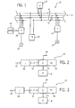
- Network 10 is particularly well-suited to managing automated functions, such as control and monitoring functions in industrial environments such as manufacturing, material handling, steady flow and batch processes, and so forth. Accordingly, network 10 provides for exchange of power and data signals within the network for appropriate control of the various networked devices.
- cabling such as a 4-conductor cable 12 is routed among the various networked devices, and includes a pair of power conductors 14 which flank pair of data signal conductors 16.
- data conductors 16 are located between power conductors 14, and all conductors may be terminated at desired locations by insulation displacement connectors (not shown).
- a power main or normal supply 20 provides power to the power conductors 14.
- Various power supplies may be provided in the network, depending upon the lengths of the media employed, spacing between the devices and power supplies, and so forth.
- Networked devices represented generally by reference numeral 18, are coupled to both the power and the data conductors of the cable and are designed to carry out specific functions in the network.
- devices 18 may include switchgear, motor controllers, motor starters, circuit breakers, logic controllers, monitoring stations, and so forth.
- a supply of backup power from a backup power module 22 in Figure 1 may be applied to one or more of the devices 18 to ensure the supply of backup power in the event of loss of power from the network.
- electrical loads such as motors 24 in the implementation of Figure 1 are linked to the devices.
- sufficient power is provided by the network, and by backup power supply module 22, for operation of the devices.
- Logical signals are also provided by the network via the data conductors 16. Separate power, typically at higher voltages and current ratings, is supplied to the devices 18 intended to command operation of a load 24.
- FIGS 2-6 illustrate present exemplary implementations of power supply module 22 designed to apply power to networked devices in the event of a loss or malfunction in the power supplied by network cable 12.
- Various failure modes of the network power may be envisioned.
- cable 12 may become damaged or severed, thereby interrupting power to devices downstream of power supplies 20.
- cabling extending between the primary trunk 12 and particular devices may become damaged or severed.
- Power supplies 20 may also malfunction or become damaged in operation, thereby removing power or reducing the level of power available to the networked devices. Where such eventualities can be foreseen, and where operation of particular devices 18 warrants, the present technique provides for application of power from a secondary source automatically and without interruption of a power to such devices.
- backup power module 22 includes a connection to a secondary power source 26, and a further connection to the network power source, as represented generally at arrow 28.
- the secondary power source 26 may include a wide range of power sources as described more fully below.
- the network power source 28 may be tapped from a network cable 12, or at any particular point along the network or at devices 18.
- secondary power source 26 is applied to an internal transformer 30 of the backup power module 22.
- the transformer alters the voltage of the incoming power and applies the resulting signals to a rectifier/filter/regulator circuit 32.
- Output of circuit 32 is then applied to an isolator circuit 34.
- the isolator circuit 34 effectively compares output of circuit 32 with the network power source 28, and applies power to device 18 based upon a comparison.
- the module 22 further includes a fault detection circuit 36.
- module 22 includes a control power transformer 40 which conditions and applies power to circuit 32.
- the control power transformer 40 may also supply power to other devices within the network in a conventional manner.
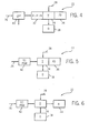
- the backup power module 22 may employ direct current power supply modules as illustrated in Figures 5 and 6. As shown in Figure 5, the backup power module 22 may thus include a direct current power supply module 42 which outputs power at a level conforming to the desired input of secondary power into the isolator circuit 34. In the implementation of Figure 6, a similar power supply module 42 is employed, but with fault relay circuitry 44 which may be powered from the power supply module 42 and thereby avoid unnecessary loading the main power supply of the network.
- the backup power module 22 may be adapted to various applications depending upon the desired type of protection and the nature of the secondary power source available.
- a 120 VAC power supply would normally be available to transformers 30 and 38, which may condition the incoming secondary power to 20 VAC.
- a control power transformer may receive incoming power, such as a level of 480 VAC, and produce output at a lower voltage level, such as 120 VAC.
- incoming power may be supplied to the DC power supply modules 42 at a level of 120 to 240 VAC, with the power supply modules 42 producing an output on the order of 24 VDC.
- power is conditioned in the module to a desired level of secondary power, such that control of switching between application of power from the network and application of power from the secondary power source is uninterrupted and automatic.
- the backup power module in the illustrated embodiment includes an internal transformer 30, a rectifier/filter/regulator circuit 32, an isolator circuit 34, and a fault detection circuit 36.
- the embodiment of Figure 7 is designed to receive power from a power source via internal transformer 30, such as at the secondary windings of the transformer (see windings 46).
- the transformer 30 transforms the voltage level of the incoming power to a desired level, such as from 120 VAC to 20 VAC.
- the internal transformer 30 may be mounted on a printed circuit board depending upon the packaging desired for the overall module.
- Power from transformer 30 is then applied to circuit 32 which includes a rectifier 48.
- the rectifier produces DC power which is applied to an output bus having a high side 52 and a low side 50.
- a filtering capacitor 54 such as a 75 microFarad capacitor serves to smooth the output of rectifier 48.
- Direct current power is then applied to a voltage regulator 56 at an input side 58 thereof.
- the voltage regulator removes ripple from the DC power by virtue of an additional filtering capacitor 62, such as a 10 microFarad capacitor.
- Output from the voltage regulator 56 is available at output line 60.
- the voltage regulator circuitry is adjustable by virtue of resistors 64 and 66.
- circuit 32 further includes a pair of diodes 68 and 70 which offer protection to the regulator 56. Finally, a further noise reduction filtering capacitor 72 is provided, such as a 0.1 microFarad capacitor.
- various types of human feedback devices may be provided for indicating the operative state of module 22.
- a current limiting resistor 74 in series with an LED 76 to indicate that the DC bus is currently being powered from the secondary power source. Additional visual or other indicators may be provided for easily detecting whether power is being provided from the secondary power source or from the network power source as described more fully below.
- circuit 34 includes a dual diode isolator 78.
- isolator circuit 78 is a Schottke diode circuit providing a low voltage drop, on the order of 0.4 volts. The isolator circuit offers protection against flow through to the downstream device in the event of a short circuit, thereby avoiding the unwanted application of power to the downstream device.
- Output of the isolator circuit 78 is provided at terminal 80.
- the normal network power is available at terminals 82. That is, output of the regulator 56 is supplied to one side of isolator circuit 78, while the typically higher voltage of the network power source is applied to the opposite side of isolator circuit 78.
- isolator circuit 78 serves as a comparison circuit capable of outputting power at terminal 80 depending upon the balance between the inputs (e.g. voltage levels) from the secondary power source and the network power source.
- Fault detection circuit 36 is also coupled to the output of voltage regulator 56 and to the network power source.
- Circuit 36 thus includes a current limiting resistor 84 and a resistor 86 designed to bias a solid state switch 88.
- Switch 88 is coupled between the high and low voltage terminals of the network power supply, and is forward biased when the network power supply is normally operative.
- a relay coil 92 is powered from the backup or secondary power supply through the voltage regulator 56 to provide for an alarm in the event of switching between the normal network power supply and supply from the secondary power source.
- a diode 90 serves to protect switch 88 when relay coil 92 is switched off. It should be noted that in the illustrated embodiment, relay coil 92 is powered on during normal operation by the backup power module, and in particular by power from the secondary power source.
- Power loss relays are operated under the control of relay coil 92.
- the relay 94 may be normally open or normally closed, and may be coupled to visual, auditory, or other alarms to indicate to operations personnel that power is being supplied from the secondary power source.
- incoming power from the secondary power source is transformed and conditioned to a desired level for application to isolator circuit 78.
- the secondary power source portion of module 22 preferably produces power at a voltage level which is lower than the normal voltage level of the network, but which is capable of powering the downstream devices.
- the module 22 may be adjusted to provide backup power at a level on the order of 14 to 20 VDC.
- the voltage level of the backup power available may be fixed at a pre-determined level, with the effective comparison made by isolator circuit 78 being with this fixed predetermined level.
- FIG. 8 illustrates a variation of the circuitry of Figure 7 in accordance with the diagram of Figure 3.
- all circuits 32, 34 and 36 are substantially identical to the circuitry described above, but rectifier 48 receives power from a separate source, such as from windings 96 of an external transformer 38.
- external transformer 38 includes windings 96 for transforming incoming power from a level of 120 VAC to a level of 20 VAC. The transformed power is then applied to rectifier 48 as described above.
- the circuits 32, 34 and 36 are again identical to those described with reference to Figure 7, but power from windings 98 of a control power transformer 40 are applied to rectifier 48.
- the windings 98 of the control power transformer provide for input of 480 VAC and output of 20 VAC.
- Other windings within the control power transformer may provide output on the order of 120 VAC.
- FIG. 10 The embodiment illustrated in Figure 10 is identical to the former embodiments in so much as the isolator circuit and fault detection circuit 36 are concerned.
- a DC power supply module 42 where a DC power supply module 42 is available, incoming power may be supplied to the module as indicated at reference numeral 100, such as in the form of 120-240 VAC.
- the DC power supply module 42 then provides output at high and low sides of a bus 120, such as at a desired voltage level of 24 VDC.
- a voltage regulator may be provided within the DC power supply module or external to the module for adjustment of the power from the secondary power source to a desired level, such as below the normal network voltage level.
- the embodiment of Figure 11 provides a series of fault relays.
- a DC power supply module is again employed as in the embodiment of Figure 10.
- a pair of relays are provided for indicating fault conditions.
- these include a first relay coil 104 coupled to the network power supply terminal, along with a corresponding relay 106.
- a second coil 108 is coupled to the backup or secondary power source and is accompanied by corresponding relay 110.
- the use of two relay coils and associated relays as illustrated in Figure 11 affords visual, auditory, or other alarms or output signals to indicate that the network power supply is operative or inoperative, and that the backup power supply is operative or inoperative.
- modules described above may be combined or altered to accommodate specific application needs.
- relays or other circuitry may be provided in any of the described embodiments to indicate the operative state of the module, the network or secondary power supply, which power supply is currently coupled to the downstream device.
- the module described herein may be configured as a separate and independent component, or may be incorporated into various networked components or power supplies coupled to the network.
- a network is configured to apply power and data signals to networked devices for operation of the devices.
- a backup power supply module is coupled to the source of network power and to a secondary power source.
- the secondary power source may have an adjustable voltage level or a level fixed with relation to the network power voltage level. In the event of a loss or insufficiency of network power, power from the secondary source is automatically applied to the connected device or devices.
- the device may be programmed for certain failure modes and the secondary power source provides the power needed for operation in the event of loss of network power.
Landscapes
- Business, Economics & Management (AREA)
- Emergency Management (AREA)
- Engineering & Computer Science (AREA)
- Power Engineering (AREA)
- Stand-By Power Supply Arrangements (AREA)
- Small-Scale Networks (AREA)
Abstract
Description
Claims (28)
- A method for providing power to a networked component coupled to a data and power network, the method comprising:applying data and power signals to the networked component via the network;providing power from a secondary power or backup power source;applying power to the networked component from the secondary or backup power source in the event of an interruption or malfunction in the power available from the network.
- The method of claim 1, comprising:applying at least the power signal to a secondary power module;conditioning power from the secondary or backup power source in the secondary power module; andapplying power to the networked component from the network during normal operation, and from the secondary or backup power source in the event of a predetermined drop in voltage of power from the network.
- The method of claim 1, comprising:detecting a network voltage level available from a data and power signal delivery cable;conditioning power from the secondary or backup power source to a secondary voltage level;comparing the network voltage level to the secondary voltage level; andpermitting power to be applied to the networked component by the network or to cause power to be applied to the networked component from the secondary or backup power source based upon the comparison.
- The method of claim 1, comprising:coupling a component to a network configured to apply power and data signals to the component;applying power to the component via a network power and data cable;coupling the source of secondary or backup power to the component and to the network; andautomatically applying power to the component from the source of secondary or backup power if power from the network power and data cable is interrupted.
- The method of any preceding claim, wherein power is applied to the networked component from the secondary power or backup source when a voltage level of power from the network is lower than a preferably adjustable voltage level of power from the secondary or backup power source or the secondary power module.
- The method of any preceding claim, wherein the voltage level of power from the secondary or backup power source or the secondary power module is maintained below a normal voltage level of power from the network.
- The method of any preceding claim, comprising generating an alarm indicating that power is being applied to the networked component from the secondary or backup power source or the secondary power module, wherein the alarm, if desired, includes a visual indication viewable by an operator and wherein power for the alarm is particularly provided by the secondary or backup power source or the secondary power module.
- The method of any preceding claim, comprising resuming application of power to the networked component from the network when the voltage level of power from the network rises above a desired level being preferably the voltage level of power from the secondary or backup power source or the secondary power module.
- The method of any preceding claim, wherein transition of application of power from the network to application of power from the secondary or backup power source or the secondary power module occurs without loss of power to the networked component.
- The method of any preceding claim, wherein the network voltage level and the secondary voltage level or the voltage level of the secondary or backup power source or the secondary power module are compared by a dual diode isolator circuit.
- The method of any preceding claim, wherein power from the secondary or backup power source or the secondary power module is conditioned to provide direct current power at a secondary voltage level below the network voltage level being preferably at least 6 volts below a normal network voltage level.
- The method of any preceding claim, further comprising providing a signal indicating that voltage is being applied to the networked component from the secondary or backup power source or the secondary power module, wherein, if desired, the signal is applied to a visual indicator.
- The method of any preceding claim, further comprising providing a signal indicating that the network voltage level and the secondary voltage level or the voltage level of the secondary or backup power source or the secondary power module are detected.
- The method of claim 4, wherein a voltage level of power from the network power and data cable is compared to a voltage level of power from the source of secondary or backup power and power from the source of secondary or backup power is applied to the component based upon the comparison.
- The method of claim 4 or 14, wherein a voltage level of the power from the source of secondary or backup power is set to a level below a normal voltage level of power from the network power and data cable.
- The method of any preceding claim, wherein when power is applied to the component from the source of secondary or backup power or the secondary power module, logical operations of the component are continued without data from the network power and data cable.
- The method of any preceding claim, comprising conditioning alternating current power to direct current power to provide the source of secondary or backup power or the source of the secondary power module.
- The method of any preceding claim, wherein transition from applying power from the network power and data cable to applying power from the source of the secondary or backup power or the secondary power module is effected without interruption of power to the component.
- A network for providing power and data to a component, the network comprising:a networked component configured to receive power and data from a network during normal operation;a network cable coupled to the component for applying power and data signals to the component; anda backup power module coupled to the component and configured automatically to apply backup power to the component if power applied to the component by the network cable falls below a predetermined voltage level.
- The network of claim 19, wherein the backup power module included a comparison circuit configured to transition application of power from the network power and data cable to application of power from a secondary power source based upon comparison of voltage levels.
- The network of claim 20, wherein the comparison circuit includes a dual diode isolator.
- The network of claim 19, 20 or 21, wherein the backup power module includes:a network power circuit configured to detect power from the network cable;a backup power circuit configured to draw power from a backup power source;an output circuit configured to apply power to the networked component; anda comparison circuit configured to compare a network voltage level and a backup voltage level and to permit power to be applied to the networked component from data and power cable or to cause the output circuit to apply power to the networked component based upon the comparison.
- The network of claim 22, wherein the comparison circuit is configured to cause the output circuit to apply power to the networked component from the network power and data cable if the network voltage level exceeds the backup voltage level by a predetermined amount.
- The network of any of claims 19 to 23, wherein the backup power module provides power at a voltage level below a normal operating voltage range of the network.
- The network of any of claims 19 to 24, wherein the backup power module is configured automatically to transition from application of power from the network power and data cable to application of power from a secondary power source without interruption of power to the component and/or wherein the backup power module is configured automatically to transition from application of power from the secondary power source to application of power from the network power and data cable without interruption of power to the component.
- A power and data network comprising:a networked component configured to receive power and data from a network during normal operation;a network cable coupled to the component for applying power and data to the component from the network during normal operation;a network interface circuit configured for connection to the network data and power cable and for detecting a network power level;a secondary power source circuit configured to receive and condition power from a secondary source to a secondary power level;an output circuit configured to apply power to a networked component coupled to the network and normally receiving power from the network; anda comparison circuit configured to compare the network voltage level to a desired voltage level and to permit power to be applied to the networked component from the data and power network or to cause the output circuit to apply power to the networked component from the secondary power source circuit based upon the comparison.
- The network claim 26, wherein the desired voltage level is the secondary voltage level.
- The network of claim 26 or 27, wherein the secondary power circuit maintains the secondary voltage level at a predetermined amount below a normal operating range of the network voltage level.
Applications Claiming Priority (2)
| Application Number | Priority Date | Filing Date | Title |
|---|---|---|---|
| US953383 | 1992-09-30 | ||
| US09/953,383 US7191351B2 (en) | 2001-09-12 | 2001-09-12 | Method and network for providing backup power to networked devices |
Publications (3)
| Publication Number | Publication Date |
|---|---|
| EP1311049A2 true EP1311049A2 (en) | 2003-05-14 |
| EP1311049A3 EP1311049A3 (en) | 2005-01-19 |
| EP1311049B1 EP1311049B1 (en) | 2017-12-27 |
Family
ID=25493907
Family Applications (1)
| Application Number | Title | Priority Date | Filing Date |
|---|---|---|---|
| EP02017573.3A Expired - Lifetime EP1311049B1 (en) | 2001-09-12 | 2002-08-07 | Method and network for providing backup power to networked devices |
Country Status (3)
| Country | Link |
|---|---|
| US (1) | US7191351B2 (en) |
| EP (1) | EP1311049B1 (en) |
| CA (1) | CA2396450C (en) |
Cited By (1)
| Publication number | Priority date | Publication date | Assignee | Title |
|---|---|---|---|---|
| CN113691022A (en) * | 2021-10-27 | 2021-11-23 | 江苏泽宇智能电力股份有限公司 | Self-adjusting noise-reduction type convertor station remote intelligent inspection system |
Families Citing this family (5)
| Publication number | Priority date | Publication date | Assignee | Title |
|---|---|---|---|---|
| EP1361664B1 (en) * | 2002-05-10 | 2008-08-06 | Texas Instruments Incorporated | LDO regulator with sleep mode |
| US7081735B1 (en) | 2003-09-16 | 2006-07-25 | Rockwell Automation Technologies, Inc. | System and method for bypassing a motor drive |
| US7003412B2 (en) * | 2003-09-17 | 2006-02-21 | Rockwell Automation Technologies, Inc. | Method and system for verifying voltage in an electrical system |
| US20080137266A1 (en) * | 2006-09-29 | 2008-06-12 | Rockwell Automation Technologies, Inc. | Motor control center with power and data distribution bus |
| US10205628B2 (en) * | 2016-06-07 | 2019-02-12 | Time Warner Cable Enterprises Llc | Methods and apparatus for determining and/or controlling backup power in a communications system |
Family Cites Families (16)
| Publication number | Priority date | Publication date | Assignee | Title |
|---|---|---|---|---|
| US5172292A (en) * | 1990-01-18 | 1992-12-15 | Roi Development Corp. Dba Newmar | Apparatus for protecting electronic equipment powered from a marine power source |
| JPH0556577A (en) * | 1991-08-27 | 1993-03-05 | Seikosha Co Ltd | Power supply controller |
| US5574436A (en) * | 1993-07-21 | 1996-11-12 | Sisselman; Ronald | Smoke detector including an indicator for indicating a missing primary power source which is powered by a substantially nonremovable secondary power source |
| US5569997A (en) * | 1993-10-04 | 1996-10-29 | Ford Motor Company | Power supply for volatile memory devices and portable electrical appliance in vehicles |
| US5705979A (en) * | 1995-04-13 | 1998-01-06 | Tropaion Inc. | Smoke detector/alarm panel interface unit |
| DE19602171A1 (en) * | 1996-01-23 | 1997-07-24 | Teves Gmbh Alfred | Wiring a voltage regulator in the vehicle electrical system |
| US5745355A (en) * | 1996-06-25 | 1998-04-28 | Exide Electronics Corporation | Wireless selective tripping of AC power systems connected in parallel |
| US5945631A (en) * | 1996-09-16 | 1999-08-31 | Sony Corporation | IEEE 1394 active wall disconnect and aircraft qualified cable |
| CA2258340A1 (en) * | 1997-01-31 | 1998-08-06 | Ira S. Faberman | Uninterruptible power supply |
| JP2000014043A (en) * | 1998-06-05 | 2000-01-14 | Internatl Business Mach Corp <Ibm> | Uninterruptive power supply |
| US6311279B1 (en) * | 1998-10-27 | 2001-10-30 | Compaq Computer Corporation | Network node with internal battery backup |
| US6473608B1 (en) * | 1999-01-12 | 2002-10-29 | Powerdsine Ltd. | Structure cabling system |
| US6643566B1 (en) * | 1999-01-12 | 2003-11-04 | Powerdsine Ltd. | System for power delivery over data communication cabling infrastructure |
| TW426271U (en) * | 1999-02-03 | 2001-03-11 | Delta Electronics Inc | External backup power supply |
| JP4219516B2 (en) * | 1999-12-20 | 2009-02-04 | 富士通株式会社 | POWER CONTROL DEVICE, POWER CONTROL METHOD, AND STORAGE MEDIUM |
| JP4647747B2 (en) * | 2000-06-08 | 2011-03-09 | 富士通セミコンダクター株式会社 | DC-DC converter and semiconductor integrated circuit device for DC-DC converter |
-
2001
- 2001-09-12 US US09/953,383 patent/US7191351B2/en not_active Expired - Lifetime
-
2002
- 2002-08-01 CA CA 2396450 patent/CA2396450C/en not_active Expired - Fee Related
- 2002-08-07 EP EP02017573.3A patent/EP1311049B1/en not_active Expired - Lifetime
Cited By (2)
| Publication number | Priority date | Publication date | Assignee | Title |
|---|---|---|---|---|
| CN113691022A (en) * | 2021-10-27 | 2021-11-23 | 江苏泽宇智能电力股份有限公司 | Self-adjusting noise-reduction type convertor station remote intelligent inspection system |
| CN113691022B (en) * | 2021-10-27 | 2021-12-24 | 江苏泽宇智能电力股份有限公司 | Self-adjusting noise-reduction type convertor station remote intelligent inspection system |
Also Published As
| Publication number | Publication date |
|---|---|
| US7191351B2 (en) | 2007-03-13 |
| CA2396450A1 (en) | 2003-03-12 |
| CA2396450C (en) | 2010-10-26 |
| EP1311049A3 (en) | 2005-01-19 |
| EP1311049B1 (en) | 2017-12-27 |
| US20030051176A1 (en) | 2003-03-13 |
Similar Documents
| Publication | Publication Date | Title |
|---|---|---|
| CN100367623C (en) | Ship electrical system | |
| US8450876B2 (en) | System and method for limiting losses in an uninterruptible power supply | |
| US7687935B2 (en) | Electrical power control system | |
| US7710697B2 (en) | Hybrid system for electronically resetable circuit protection | |
| JP2001075880A (en) | Device for electronically monitoring supply currents of module connected with bus | |
| US7237134B2 (en) | Backup power module for industrial control and monitoring network | |
| US12334775B2 (en) | Power supply system and control method | |
| US20090322152A1 (en) | Isolation control high speed transfer switch for uninterruptible power supply, power supply system using the switch and isolation control high speed transfer switching method | |
| CN107666176A (en) | Equipment for monitoring/controlling power change-over switch | |
| CA2396450C (en) | Method and network for providing backup power to networked devices | |
| EP2278686B1 (en) | Method and apparatus for providing uninterruptible power | |
| EP2244353B1 (en) | Energy saving device | |
| JP3908203B2 (en) | Anomaly detector for current transformer in distributed power system | |
| CN110445421B (en) | Starting circuit of motor, control method of starting circuit and engineering machinery | |
| JP4471282B2 (en) | Power flow control method for low voltage distribution system | |
| KR20190096634A (en) | Motor control centor comprising motor protection relay | |
| CN218940767U (en) | Power supply switching system and power supply | |
| RU2150775C1 (en) | Power supply system of shipboard radar station | |
| US5708357A (en) | Power circuit for electronic controller | |
| KR200301007Y1 (en) | Uninterruptible power supply | |
| KR20190096633A (en) | Motor protection relay and motor protection system comprising the same | |
| JPH09261894A (en) | Combined power backup system | |
| JP2005287277A (en) | Power supply control system | |
| RU11633U1 (en) | SYSTEM OF POWER SUPPLY OF SHIP RADAR STATION | |
| JPH0823629A (en) | Slave switch station |
Legal Events
| Date | Code | Title | Description |
|---|---|---|---|
| PUAI | Public reference made under article 153(3) epc to a published international application that has entered the european phase |
Free format text: ORIGINAL CODE: 0009012 |
|
| AK | Designated contracting states |
Designated state(s): AT BE BG CH CY CZ DE DK EE ES FI FR GB GR IE IT LI LU MC NL PT SE SK TR |
|
| AX | Request for extension of the european patent |
Extension state: AL LT LV MK RO SI |
|
| PUAL | Search report despatched |
Free format text: ORIGINAL CODE: 0009013 |
|
| AK | Designated contracting states |
Kind code of ref document: A3 Designated state(s): AT BE BG CH CY CZ DE DK EE ES FI FR GB GR IE IT LI LU MC NL PT SE SK TR |
|
| AX | Request for extension of the european patent |
Extension state: AL LT LV MK RO SI |
|
| 17P | Request for examination filed |
Effective date: 20050517 |
|
| AKX | Designation fees paid |
Designated state(s): DE FR GB |
|
| 17Q | First examination report despatched |
Effective date: 20150311 |
|
| GRAP | Despatch of communication of intention to grant a patent |
Free format text: ORIGINAL CODE: EPIDOSNIGR1 |
|
| INTG | Intention to grant announced |
Effective date: 20170927 |
|
| GRAA | (expected) grant |
Free format text: ORIGINAL CODE: 0009210 |
|
| GRAS | Grant fee paid |
Free format text: ORIGINAL CODE: EPIDOSNIGR3 |
|
| AK | Designated contracting states |
Kind code of ref document: B1 Designated state(s): DE FR GB |
|
| REG | Reference to a national code |
Ref country code: GB Ref legal event code: FG4D |
|
| REG | Reference to a national code |
Ref country code: DE Ref legal event code: R096 Ref document number: 60249233 Country of ref document: DE |
|
| REG | Reference to a national code |
Ref country code: FR Ref legal event code: PLFP Year of fee payment: 17 |
|
| REG | Reference to a national code |
Ref country code: DE Ref legal event code: R097 Ref document number: 60249233 Country of ref document: DE |
|
| PGFP | Annual fee paid to national office [announced via postgrant information from national office to epo] |
Ref country code: DE Payment date: 20180829 Year of fee payment: 17 Ref country code: FR Payment date: 20180827 Year of fee payment: 17 |
|
| PLBE | No opposition filed within time limit |
Free format text: ORIGINAL CODE: 0009261 |
|
| STAA | Information on the status of an ep patent application or granted ep patent |
Free format text: STATUS: NO OPPOSITION FILED WITHIN TIME LIMIT |
|
| PGFP | Annual fee paid to national office [announced via postgrant information from national office to epo] |
Ref country code: GB Payment date: 20180828 Year of fee payment: 17 |
|
| 26N | No opposition filed |
Effective date: 20180928 |
|
| REG | Reference to a national code |
Ref country code: DE Ref legal event code: R119 Ref document number: 60249233 Country of ref document: DE |
|
| GBPC | Gb: european patent ceased through non-payment of renewal fee |
Effective date: 20190807 |
|
| PG25 | Lapsed in a contracting state [announced via postgrant information from national office to epo] |
Ref country code: FR Free format text: LAPSE BECAUSE OF NON-PAYMENT OF DUE FEES Effective date: 20190831 Ref country code: DE Free format text: LAPSE BECAUSE OF NON-PAYMENT OF DUE FEES Effective date: 20200303 |
|
| PG25 | Lapsed in a contracting state [announced via postgrant information from national office to epo] |
Ref country code: GB Free format text: LAPSE BECAUSE OF NON-PAYMENT OF DUE FEES Effective date: 20190807 |