EP1310870A1 - Information processing device, information processing method, and robot apparatus - Google Patents
Information processing device, information processing method, and robot apparatus Download PDFInfo
- Publication number
- EP1310870A1 EP1310870A1 EP01956926A EP01956926A EP1310870A1 EP 1310870 A1 EP1310870 A1 EP 1310870A1 EP 01956926 A EP01956926 A EP 01956926A EP 01956926 A EP01956926 A EP 01956926A EP 1310870 A1 EP1310870 A1 EP 1310870A1
- Authority
- EP
- European Patent Office
- Prior art keywords
- information processing
- shared memory
- data
- accesses
- processing processes
- Prior art date
- Legal status (The legal status is an assumption and is not a legal conclusion. Google has not performed a legal analysis and makes no representation as to the accuracy of the status listed.)
- Withdrawn
Links
Images










Classifications
-
- G—PHYSICS
- G06—COMPUTING OR CALCULATING; COUNTING
- G06F—ELECTRIC DIGITAL DATA PROCESSING
- G06F9/00—Arrangements for program control, e.g. control units
- G06F9/06—Arrangements for program control, e.g. control units using stored programs, i.e. using an internal store of processing equipment to receive or retain programs
- G06F9/46—Multiprogramming arrangements
- G06F9/54—Interprogram communication
- G06F9/544—Buffers; Shared memory; Pipes
-
- G—PHYSICS
- G05—CONTROLLING; REGULATING
- G05B—CONTROL OR REGULATING SYSTEMS IN GENERAL; FUNCTIONAL ELEMENTS OF SUCH SYSTEMS; MONITORING OR TESTING ARRANGEMENTS FOR SUCH SYSTEMS OR ELEMENTS
- G05B19/00—Program-control systems
- G05B19/02—Program-control systems electric
- G05B19/418—Total factory control, i.e. centrally controlling a plurality of machines, e.g. direct or distributed numerical control [DNC], flexible manufacturing systems [FMS], integrated manufacturing systems [IMS] or computer integrated manufacturing [CIM]
- G05B19/41865—Total factory control, i.e. centrally controlling a plurality of machines, e.g. direct or distributed numerical control [DNC], flexible manufacturing systems [FMS], integrated manufacturing systems [IMS] or computer integrated manufacturing [CIM] characterised by job scheduling, process planning, material flow
- G05B19/4187—Total factory control, i.e. centrally controlling a plurality of machines, e.g. direct or distributed numerical control [DNC], flexible manufacturing systems [FMS], integrated manufacturing systems [IMS] or computer integrated manufacturing [CIM] characterised by job scheduling, process planning, material flow by tool management
-
- G—PHYSICS
- G06—COMPUTING OR CALCULATING; COUNTING
- G06F—ELECTRIC DIGITAL DATA PROCESSING
- G06F9/00—Arrangements for program control, e.g. control units
- G06F9/06—Arrangements for program control, e.g. control units using stored programs, i.e. using an internal store of processing equipment to receive or retain programs
- G06F9/46—Multiprogramming arrangements
- G06F9/54—Interprogram communication
- G06F9/546—Message passing systems or structures, e.g. queues
-
- G—PHYSICS
- G06—COMPUTING OR CALCULATING; COUNTING
- G06N—COMPUTING ARRANGEMENTS BASED ON SPECIFIC COMPUTATIONAL MODELS
- G06N3/00—Computing arrangements based on biological models
- G06N3/004—Artificial life, i.e. computing arrangements simulating life
- G06N3/008—Artificial life, i.e. computing arrangements simulating life based on physical entities controlled by simulated intelligence so as to replicate intelligent life forms, e.g. based on robots replicating pets or humans in their appearance or behaviour
-
- Y—GENERAL TAGGING OF NEW TECHNOLOGICAL DEVELOPMENTS; GENERAL TAGGING OF CROSS-SECTIONAL TECHNOLOGIES SPANNING OVER SEVERAL SECTIONS OF THE IPC; TECHNICAL SUBJECTS COVERED BY FORMER USPC CROSS-REFERENCE ART COLLECTIONS [XRACs] AND DIGESTS
- Y02—TECHNOLOGIES OR APPLICATIONS FOR MITIGATION OR ADAPTATION AGAINST CLIMATE CHANGE
- Y02P—CLIMATE CHANGE MITIGATION TECHNOLOGIES IN THE PRODUCTION OR PROCESSING OF GOODS
- Y02P90/00—Enabling technologies with a potential contribution to greenhouse gas [GHG] emissions mitigation
- Y02P90/02—Total factory control, e.g. smart factories, flexible manufacturing systems [FMS] or integrated manufacturing systems [IMS]
Definitions
- This invention relates to an information processing device and an information processing method for carrying out various processing using a plurality of processes, and a robot device which has its motion or the like determined by a plurality of processes.
- the proceeding status of the task is different depending on the weight, priority, processing cycle and the like of the processing of each process. For example, if the processing result (data) of a process A which is executed at a high speed is transmitted from the process A to a process B which is executed at a low speed, the process B is filled with the received queues from the process A and the received queues overflow.
- the process B is filled with the received queues from the process A and the received queues overflow.
- handshaking between the processes must be carried out by a certain technique. For example, the following three techniques are proposed (Basics and Application of OS, A.S.Tannenbaum, Toppan, p.464):
- the blocking transmission (1) is a transmission technique in which the transmitting side waits until transmission is completed and the queues at destination are emptied.
- the non-blocking transmission which involves copying (2) is a transmission technique in which data is copied into an area of the system so as to let the process on the transmitting side proceed.
- the non-blockingtransmission which involves interrupt (3) is a transmission technique in which writing to a transmission buffer is carried out by interrupt processing.
- the above-described blocking transmission (1) is a safe and secure transmission technique
- this technique is not practical because when freely changing the connection of software or process as a component (for example, object-oriented software, hereinafter referred to as object), a deadlock may easily occur depending on the way of connection.
- Object-oriented software is constituted, for example, in a pet-like robot device or the like.
- a pet-like robot device makes, for example, gestures similar to those of a certain animal in accordance with various processing (for example, data communication) through inter-object communication (or inter-process communication).
- the above-described non-blocking transmission which involves copying (2) is less efficient because it repeats redundant copying.
- an increase in the number of connections causes an increase in the number of times of copying and hence the number of memories used as buffers.
- an object of the present invention to provide an information processing device, an information processing method, and a robot device which can easily realize smooth inter-process communication.
- An information processing device comprises control means having a plurality of information processing processes and adapted for carrying out control processing based on inter-process communication carried out between the information processing processes, the control means controlling accesses by the plurality of information processing processes to a shared memory shared by the plurality of information processing processes and thus carrying out inter-process communication.
- the information processing processes, each of which independently executes processing, share data on the shared memory and thus execute various processing.
- An information processing method has a plurality of information processing processes and is adapted for carrying out control processing based on inter-process communication carried out between the information processing processes, the information processing method comprising controlling accesses by the plurality of information processing processes to a shared memory shared by the plurality of information processing processes and thus carrying out inter-process communication.
- the information processing processes each of which independently executes processing, share data on the shared memory and thus execute various processing.
- a robot device comprises output means for expressing a motion, and control means having a plurality of information processing processes and adapted for carrying out control processing of the output means based on inter-process communication carried out between the information processing processes, the control means controlling accesses by the plurality of information processing processes to a shared memory shared by the plurality of information processing processes and thus carrying out inter-process communication.
- the information processing processes each of which independently executes processing, share data on the shared memory and thus execute the control processing of the output means.
- control means having a plurality of information processing processes and adapted for carrying out control processing based on inter-process communication carried out between the information processing processes controls accesses by the plurality of information processing processes to a shared memory shared by the plurality of information processing processes and thus carries out inter-process communication
- the information processing processes each of which independently executes processing, can share data on the shared memory and thus execute the various processing.
- control processing is carried out based on inter-process communication carried out between the information processing processes, then accesses by the plurality of information processing processes to a shared memory shared by the plurality of information processing processes are controlled to carry out inter-process communication, the information processing processes, each of which independently executes processing, can share data on the shared memory and thus execute the various processing.
- control means having a plurality of information processing processes and adapted for carrying out control processing of output means based on inter-process communication carried out between the information processing processes controls accesses by the plurality of information processing processes to a shared memory shared by the plurality of information processing processes and thus carries out inter-process communication
- the information processing processes each of which independently executes processing, can share data on the shared memory and thus execute the control processing of the output means.
- the present invention is applied to a pet-like robot device in which object-oriented software is constructed.
- the pet-like robot device makes, for example, gestures similar to those of a certain animal in accordance with various processing (for example, data communication) through inter-object communication (or inter-process communication).
- processing for example, data communication
- inter-object communication or inter-process communication
- this invention is not limited to the pet-like robot device and can be applied to other devices within the scope of this invention.
- the structure of the robot device will be first described and then essential parts of this invention will be described in detail.
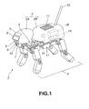
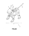
- a robot device 1 is a so-called pet-like robot device which has a dog-like shape as a whole and can walk with four legs, as shown in Fig.1. That is, the robot device 1 includes a moving unit 3 mounted on a body 2, and the body 2 is constituted by a head part 2A and a trunk part 2B.
- the head part 2A has arranged thereon a microphone 4, a touch sensor 5, a television camera 6 capable of realizing stereoscopic vision, a remote-controlled infrared receiving portion 7 and the like, and can acquire various information by using these parts.
- the head part 2A also has an image display portion 9 and a speaker 10 arranged thereon and can output various information.
- the structure of the head part 2A is not limited to such a structure.
- the image display portion 9 may be constituted by an LED (light-emitting diode) so as to give expressions.
- the trunk part 2B has an operator 11 arranged on its back portion and also has an antenna 12 arranged at a site corresponding to the tail, so that the operation by the user can be detected via the operator 11 and the antenna 12.
- the trunk part 2B also has a slot so that an IC card is loaded into the slot to enable execution of version up of the software and the like.
- a controller 15 for processing various information inputted and outputted via the head part 2A and operation information of the operator 11 and the like, a power-supply unit 14 for supplying power to each part, and a communication unit 16 for transmitting and receiving various information via the antenna 12 are arranged on the trunk part 2B, and a battery 17 is arranged on the lower part thereof.
- the moving unit 3 is formed by arranging four legs, each of which has an actuator and an angle detection sensor at a site corresponding to the joint.
- the moving unit 3 is connected to the body 2 by a serial bus and operates under the control of the body 2.
- the robot device 1 can move by four-legged walking.
- the rear legs can be detached from the body 2.
- a moving unit having wheels can be attached instead of the rear legs.
- the form of this robot device 1 can be changed between the four-legged moving form (hereinafter referred to as four-legged type) and the wheeled moving form (hereinafter referred to as wheeled type) in accordance with the preference of the user.
- Fig.2 is a block diagram showing the structure of this robot device 1.
- a program medium 20 having a processing program recorded thereon is connected to a central processing unit 22 via a peripheral unit 21, and the central processing unit 22 executes the processing procedure recorded on the program medium 20.
- the central processing unit 22 is also connected with robot device components 24, 25, 26, which are the actuators and sensors of the moving unit 3, the television camera 6, the operator 11 and the like via the peripheral unit 21, and can thus control the overall operation.
- the central processing unit 22 is connected with a one-chip microcomputer 27 for power control which constitutes the power-supply unit 14, via the peripheral unit 21, and controls the operation of the one-chip microprocessor 27 to supply power to the whole body from the battery 17, and in a power-saving mode, to supply power to the whole body from a button battery 29 instead of the battery 17.
- a one-chip microcomputer 27 for power control which constitutes the power-supply unit 14, via the peripheral unit 21, and controls the operation of the one-chip microprocessor 27 to supply power to the whole body from the battery 17, and in a power-saving mode, to supply power to the whole body from a button battery 29 instead of the battery 17.
- the central processing unit 22 has the function of control means which has a plurality of information processing processes (objects) and is adapted for carrying out control processing based on inter-process communication (inter-object communication) carried out between the information processing processes (objects), and which controls accesses by the plurality of information processing processes (objects) to a shared memory shared by the plurality of information processing processes (objects) and thus carries out inter-process communication (inter-object communication).
- inter-object communication inter-process communication
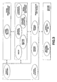
- Fig.3 is a diagram showing, as layers, the software structure of the robot device 1 of the four-legged type.
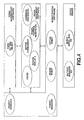
- Fig.4 is a diagram showing the software structure of the wheeled type in comparison with Fig.3.
- the lowermost layer is a device driver layer, where various device drivers are arranged.
- the device drivers carry out input/output of various information from/to the sensors and actuators of the moving unit 3 and the various robot device components arranged on the head part 2A and the like, and have software objects for processing such information.
- a battery manager device driver detects the remaining power of the battery 17 through data communication with the one-chip microcomputer 27 of the power-supply unit 14, and periodically notifies upper-layer robot system software of the detected remaining power.
- the battery manager device driver also manages the clock of the central processing unit 22 or the like, then reduces the frequency of the clock in accordance with an instruction from the robot system software and stops the operation of unnecessary devices, thus reducing the overall power consumption.
- a robot serial bus device driver (robot serial bus DD) takes sensor information and the like of the moving unit 3 connected to the serail bus arranged in the body 2 through data communication with hardware for master control of the serial bus, and notifies the upper-layer robot system software of the sensor information and the like. Moreover, the robot serial bus device driver sends control data of the actuator, audio signals and the like outputted from the robot system software, to the respective devices.
- the robot serial bus device driver detects a change (addition or deletion) of a device connected to the serial bus. Furthermore, the robot serial bus device driver takes information proper to the device related to this change and thus outputs information indicating the current form of the robot device 1 to the robot system software.
- the robot system software is arranged on the upper layer than the device driver layer.
- the robot system software is constituted by software objects such as a virtual robot, a design robot, a power manager, and an object manager.
- the virtual robot converts data of a format proper to each device to a common format of the robot device and then transmits and receives the data, in data communication with the robot serial bus device driver.
- a sensor output of a potentiometer in a format proper to the device is expressed by 10-bit data resulting from analog-digital conversion
- the virtual robot converts the data of this expression to data such that the lowest one bit indicates 0.001 degrees and outputs the data in a common format in the robot device 1.
- the virtual robot outputs image data acquired by, for example, the television camera 6, to the upper software.
- the virtual robot also receives information indicating the current form of the robot device 1 from the robot serial bus device driver and put the information together.
- the virtual robot manages connection information (CPC (configurable physical component) connection information) indicating which robot component is connected in what order in the whole robot device 1, and notifies the design robot of this connection information (CPC connection information).
- CPC configurable physical component
- the virtual robot receives a notification from the robot serial bus device driver of the device driver layer and notifies the design robot.
- the design robot receives the connection information (CPC connection information) from the virtual robot, then sequentially compares the received connection information with pre-recorded connection template information, and thus selects a template suitable for the current form of the robot device 1. Moreover, in accordance with the selected template, the design robot instructs the object manager to update form-dependent software on the upper layer to form-dependent software suitable for the current form.
- connection information CPC connection information
- connection template information is described as design data in a design file.
- the object manager updates the form-dependent software to form-dependent software suitable for the current form, using the information relating to objects and connection of the respective objects sent from the design robot. Specifically, the object manager give instructions to stop the operation, cancel the connection of inter-object communication, demolish the object, and open the resource, with respect to all the objects constituting the form-dependent software. The object manager gives further instructions to load newly required objects, initialize the objects, construct connection for inter-object communication, and start up these objects.
- the connection between objects means the connection for transmitting and receiving data between the objects. This invention relates to such transmission and reception of data between the objects, and as will be described later in detail, this invention realizes inter-object communication by causing the objects to share data on a shared memory via a management object.
- the power manager communicates data with the battery manager device driver, and in accordance with the instruction from the software of the upper layer (form-independent software or form-dependent software), the power manager instructs the battery manager device driver to switch the clock and to stop the operation of the object.
- the form-dependent software is arranged on the upper layer than the robot system software, and the form-independent software is arranged on the further upper layer.
- the form-dependent software is the software which is changed in accordance with the form of the robot device 1, and the form-independent software is the upper software of the robot device 1 which is fixed irrespective of the form of the robot device 1. Therefore, various objects depending on the form of the robot device 1 exist in the form-dependent software.
- the software suitable for the form of the four-legged type and the form of the wheeled type can be easily constituted by changing the form-dependent software.
- the form-dependent software (Fig.3) is constituted by objects including a command converter, a motion network, a motion replay, a walking pattern generator, and a vision, as the objects related to the moving unit 3.
- the command converter converts a command from the form-independent software which is independent of the form, to a command suitable for the form of the robot device 1. That is, when a command which give an instruction to take a posture to sleep, rest, wake up, or move (command Sleep, Rest, Wakeup or Move) is inputted from the form-independent software as a command related to the moving unit 3, the command converter in the four-legged type converts the command to a command which gives an instruction to take a posture of sleeping, sitting, standing, or walking (command Sleeping, Sitting, Standing or Walking).
- the motion network starts a method (entry) of an object corresponding to an arrow shown in the transition view of Fig.5, in accordance with the command indicating the posture outputted from the command converter. That is, if a command for walking is inputted in the sleeping state, the corresponding entries of the motion replay object are sequentially started so that the posture is sequentially changed to sitting, standing and walking. In this case, when the ultimate walking state is reached, an entry of the walkingpattern generator corresponding to the self-loop indicating this state is started.
- the motion replay outputs joint angle command values for the corresponding posture changes by starting entries of the motion network. Specifically, the motion replay holds registered discrete joint angle command values as key data and outputs a series of angle command values by interpolation processing using the key data.
- the walkingpattern generator calculates and outputs each joint angle command value so as to move in a direction designated by the form-independent software.
- the vision is, for example, an object for image processing, and carries out processing to receive image data acquired by the television camera 6 from the virtual robot object.
- the vision identifies, for example, a red object, and detects and outputs the position and apparent size of the red object with reference to the robot device 1.
- the form-dependent software (Fig.4) is constituted by objects including a vision object which is common to this wheeled type and the four-legged type, and a command converter, a motion commander, a motion replay 2, and a wheel pattern generator which are specific to the wheeled type, as the objects related to the moving unit 3.
- the command converter converts a command from the form-independent software which is independent of the form, to a command suitable for the form of the robot device 1, similarly to the command converter in the four-legged type.
- the command converter converts commands which give instructions to take postures to sleep, rest, wake up, and move (commands Sleep, Rest, Wakeup and Move), to commands which give instructions to take postures of sleeping, resting, being ready, and going (commands Sleeping, Rest, Ready and Go).
- the motion commander receives the output from the command converter and generates a joint angle command value associated with a wheel control command. That is, when the command Sleeping is inputted, the motion commander sets the joint angle command value to neutral. In the neutral state, neither driving nor braking of the motor is carried out. Therefore, the two arms constituting the moving unit are kept hanging down and the wheels are held in a stop state.
- the motion commander When the command Rest is inputted, the motion commander generates a joint angle command value such that the two arms are bent 90 degrees at the elbow parts and held out forward while the face part of the head part 2A faces the front. The wheels are kept stopped.
- the motion commander When the command Ready is inputted, the motion commander generates a joint angle command value such that the two arms are stretched out forward while the face part of the head part 2A faces the front. In this case, too, the wheels are kept stopped.
- the motion commander When the command Go is inputted, the motion commander generates a command value such that the wheels rotate to move forward while the two arms are held similarly to the Ready state.
- the motion replay 2 controls the operation of the parts other than the wheels (for example, the operation of the two arms) with respect to a motion proper to the wheeled type, in accordance with the instruction from the motion commander.
- the wheel pattern generator generates wheel control information under the control of the motion commander.
- the form-independent software is the software which is independent of the form of the robot device 1 and has a form setting object or the like.
- the form setting object receives information which is independent of the form of the robot device 1 from the form-dependent software, and by using this information, outputs the commands (Sleep, etc.) indicating the above-described postures of the robot device 1 which are independent of the form of the robot device 1, to the form-dependent software.
- a command is issued such that the Sleep state is maintained as it is, the Rest state is shifted to the Sleep state, the Wakeup state is shifted to the Rest state, and the Move state is shifted to the Wakeup state, as shown in Fig.6.
- a command is issued such that the Sleep state is shifted to the Rest state, the Rest state is shifted to the Wakeup state, the Wakeup state is shifted to the Move state, and the Move state is continued as it is.
- a command is issued such that the Sleep state is shifted to the Wakeup state, the Rest and Wakeup states are shifted to the Move state, and the Move state is continued as it is.
- the uppermost software is formed to be independent of the form and the form-independent software transmits and receives data in the format independent of the form. Therefore, in the robot device 1, only the form-dependent software, which is dependent on the form, is changed in accordance with the form, thus enabling easy change of software in accordance with the form.
- the form-dependent software is updated by the processing at the object manager in accordance with an instruction from the design robot.
- the form-dependent software is updated by constructing the reconnection for loading, unloading, and inter-object communication of the objects constituting the form-dependent software.
- the design robot receives a notification of connection information (CPC connection information) specifying the form of the robot device 1 from the virtual robot.
- connection information CPC connection information
- the design robot instructs the object manager to update the form-dependent software and provides necessary information to the object manager.
- the virtual robot acquires information of each device connected to the serial bus via the robot serial bus device driver on the lower layer, then uses this information to prepare connection information (CPC connection information) and sends the connection information to the design robot.
- CPC connection information connection information
- the robot device 1 predetermined information is recorded into the memory of each robot component, and the information of the device connected to the serial bus in the virtual robot can be acquired together with its position information through data communication carried out via the robot serial bus device driver.
- the television camera, the speaker, the microphone, the various actuators, the sensors and the like are the basic constituent elements (CPC primitives) and a plurality of combinations of these basic constituent elements set in a link state constitute respective components (CPC models).
- CPC primitives the basic constituent elements
- a plurality of combinations of these basic constituent elements set in a link state constitute respective components (CPC models).
- one leg as a component is constituted by a plurality of basic constituent elements consisting of three motors and one switch in a specific link state.
- proper identification data are allocated to the respective components so that the respective constituent elements connected to the serial bus can be specified by using the identification data.
- the identification data includes the ID of the factory where the component was manufactured and the ID corresponding to the serial number.
- the information of each constituent element and the position information of each constituent element in the component are set by link information of each constituent element in the component and attribute information of each constituent element, and such information is held in the memory of each component together with the identification data of each component.
- the identification data is recorded in the memory of each component, and the information of the constituent elements and the position information of the constituent elements in the component are held in the body 2.
- connection information (CPC connection information) by using the respective basic constituent elements (CPC primitives) and the data structure representing the order of connection of the respective constituent elements, and notifies the design robot of the connection information.
- the connection information (CPC connection information) sent by the virtual robot is constituted by constituent element information (CPC primitive location information) corresponding to the form.
- the design robot refers to the design file on the basis of the connection information (CPC connection information) sent from the virtual robot and thus selects a connection template (that is, a label which will be described later) corresponding to the current form of the robot device 1. Moreover, in accordance with the selected template, the design robot instructs the object manager to update the form-dependent software to form-dependent software suitable for the current form.
- CPC connection information connection information
- the design robot instructs the object manager to update the form-dependent software to form-dependent software suitable for the current form.
- the design file includes description of the text data format, in which a group of constituent element information (CPC primitive location information) of each component is described with a label appended thereto, for each form of the robot device 1.
- the constituent element information (CPC primitive location information) includes the basic constituent elements (CPC primitives) of each component and the position information (CPC coordinate locator) of each constituent element.
- the position information (CPC coordinate locator) is the coordinate from a reference position set for the robot device 1.
- the coordinate is represented by a general link coordinate system and is constructed by cascade connection of a rotation matrix and a positional vector for transformation of the coordinate system.
- the label specifies the corresponding object and also specifies the necessary data for loading of the object and construction of inter-object communication.
- a design label, or a virtual label having the description which is more general and easier to understand than a design label, or a composite label constituted by combining a design label and a virtual label is applied.
- a visual label is replaced with a design label by the design robot for use.
- the design label is constituted by one or more pieces of constituent element information (CPC primitive location information) or a design label (Design Label).
- the virtual label is constituted by a design label (Design Label), a constituent element (CPC Primitive), and position information (CPC Coordinate Locator) of the constituent element (CPC Primitive).
- the design robot replaces the virtual label with the design label and sets such a design label to be effective.
- connection information CPC connection information
- the current form such as the four-legged type and the wheeled type
- various data necessary for updating the form-dependent software can be acquired.
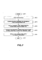
- Fig.7 is a flowchart showing the specific processing procedure of the design robot.
- the processing shifts from step SP1 to step SP2 to access the design file in accordance with the connection information (CPC connection information), thus specifying the current form of the robot device 1.
- step SP3 the processing at the design robot shifts to step SP3 to compare the constituent element information (CPC primitive location information) based on the connection information (CPC connection information) sent from the virtual robot with the constituent element information (CPC primitive location information) based on the connection information (CPC connection information) held in the design file.
- the processing at the design robot shifts to step SP4.
- the design file is accessed on the basis of the result of the comparison and a design label is detected which specifies an object corresponding to the current form and necessary data for reconstructing inter-object communication.
- connection file is accessed in accordance with the detected design label and the connection information corresponding to the label is detected, thereby acquiring necessary data for specifying the corresponding object and for reconstructing inter-object communication.
- the connection file is a file in which the connection information (connection data) is recorded in association with the label.
- the connection information (connection data) is necessary data for specifying the corresponding object and for reconstructing inter-object communication.
- connection information (connection data) is sent to the object manager, thus instructing the object manager to update the form-dependent software. After that, the processing shifts to step SP7 to end this processing procedure.
- Fig.8 is a chart showing the description of a part of the design file.
- "DRX” is the description to represent the form of the robot device 1
- 4Legged is the description to represent the form of the four-legged type.
- "Head,” “RightFrontLeg,” “LeftFrontLeg,” “RightRearLeg,” and “LeftRearLeg” represents a head part, a right front leg, a left front leg, a right rear leg, and a left rear leg, respectively.
- the first sentence specifies that the four-legged type includes a head part, a right front leg, a left front leg, a right rear leg, and a left rear leg.
- “Wheel” in the second sentence represents the wheeled type.
- the second sentence specifies that the wheeled type includes a head part, a right front leg, a left front leg, a right rear wheel, and a left rear wheel.
- the third sentence describes the arrangement of camera link in the head part.
- the fourth sentence describes a virtual label of the camera link.
- the fifth and subsequent sentences describe the position information (CPC coordinate locator) for the right front leg, the left front leg and the like in a tree format.
- Fig.9 is a chart showing the description of apart of the connection information (CPC connection information).
- the connection information is described in a text data format similar to the design file.
- "Joint" represents an interface, indicating that this portion is a connection site with another constituent element. In this case, it can be learned from the description of the second to fifth rows that a television camera is connected via five hubs or the like which are expressed as CO, CO, CO, CO, CO.
- connection information in the example of Fig.9 coincides with the four-legged type, which is described above with reference to Fig.8.
- connection file is described in a text data format.
- first sentence and second sentence describe the objects corresponding to the legs of the four-legged type and the wheels of the wheeled type, respectively, and necessary data for constructing inter-object communication for these objects.
- connection information (connection data) (description in parentheses after DRX 4Legged) from the description of the first sentence based on DRX 4Legged, and notifies the object manager of the connection information, thereby updating the form-dependent software.
- Fig.10 is a time chart showing the processing at the object manager, the virtual robot and the design robot at the time of boot.
- a do-initialize command (DoInit) is sent from the object manager to each object, and a query entry of each object is registered to the object manager or the like in accordance with the DoInit command.
- DoInit a do-initialize command
- each inter-object communication is constructed on the robot system software layer.
- connection information CPC connection information
- connection data connection information
- a DoStop command is sent to each object from the object manager.
- each object issues an error with respect to all requests and stops the operation.
- a DoDestroy command is sent to each object from the object manager. Accordingly, each object opens the source which has been used, and deletes the entry registered to the object manager. Then, each object enters the standby state.
- the robot device 1 can operate by using the software suitable for the changed form.
- a DoStop command is sent to each object from the object manager, and in accordance with this DoStop command, each object issues an error with respect to all requests and stops the operation, as shown in Fig.11.
- connection information CPC connection information
- connection data connection information
- the robot device 1 can operate by using the software suitable for the changed form.
- the processing in accordance with a DoStop command and a DoStart command is repeated in response to a state change request from the battery manager.
- the clock frequency is reduced and the operations of unnecessary devices are stopped, thus changing the state so that the robot device operates by using the button battery 29.
- the clock frequency is increased and the operation of each device is stated so that the robot device operates by using the battery 17.
- the object manager reconstructs objects constituting the form-dependent software in accordance with the notification from the design robot which is executed as described above, and thus updates the form-dependent software. Specifically, the object manager loads or unloads the objects in accordance with the notification from the design robot and reconstructs inter-object communication corresponding to the loading and unloading, thus changing the form-dependent software.
- the object manager constructs inter-object communication on the basis of the connection information (connection data) outputted from the design robot and thus secures the independence of the objects.
- connection information connection data
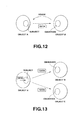
- Fig.12 is a diagram showing the basic structure of inter-object communication between two objects in this embodiment.
- the inter-object communication is carried out by using a Ready signal and a Notify signal, so that transmission of the data which exceeds the processing ability of the object (in this example, object B) is prevented.
- an object A sends data from a subject of a class 0, which is a member of the object A, to a 0 observer class, which is a member of an object B, thus invoking the method of the object B.
- the subject and the observer referred to in this case constitute so-called surrogate programs in the objects to which they belong.
- the subject sends data only when a Ready signal is being sent from the observer.
- a Ready signal must be sent once for each transmission of data.
- the object B on the observer side can wait for the completion of the processing of received data and then receive the subsequent data.
- the inter-object communication is carried out.
- the inter-object communication is realized as the transmitting side and the receiving side share data on a shared memory.
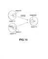
- Fig.13 is a diagram showing the basic structure of inter-object communication in a multi-observer environment.
- an object A which is a subject, can distribute data to all the observers and can also distribute data to a specific observer alone that is specified by the object ID.
- data is sent to the corresponding observer in response to a Ready signal in such a multi-observer environment.
- Each object designates the object ID specifying the object and the selector number (that is, method number) specifying the method, thereby starting (entry of) the corresponding method. Then, each object specifies an observer and sends desired data thereto.
- Fig.14 is a diagram showing the basic structure of inter-object communication is a so-called multi-subject environment.
- objects A and B are subjects and an object C is an observer.
- the observer can receive data from a plurality of subjects, and has its method for processing data invoked every time data is received. Moreover, the observer can send a Ready signal only a specific subject specified by the subject ID and thus can selectively input desired data.
- At least an object belongingto the form-dependent software layer can carry out inter-object communication by using a Ready signal and a Notify signal as described with reference to Figs.12 to 14, and also can connect to another object in accordance with a multi-observer or multi-subject connection form, when necessary. That is, an object having a plurality of observers has connection entries of the number corresponding to the number of the plurality of observers.
- Fig.15 is a diagram showing the relation between the object manager and respective objects.
- Each of the objects specifies a method in accordance with the object ID and the selector number and then exchanges data.
- Each of the objects has the selector numbers 0 to 3 allocated to the basic methods, irrespective of the corresponding subject and observer.
- a do-initialize (DoInit) command is assigned to the selector number 0 and each object is initialized by starting this DoInit command.
- a DoStart command is assigned to the selector number 1 and each object is caused to start the operation by starting this DoStart command.
- a DoStop command is assigned to the selector number 2 and each object is caused to stop the operation by starting this DoStop command.
- a DoDestroy command is assigned to the selector number 3 and each object is caused to open the resource by this DoDestroy command.
- each object in response to these requests from the object manager or in response to a request from another object, each object properly sends the service name, the selector number and the like of the observer by using a return value.
- connection information connection data
- the followingformula represents the connection information (connection data) sent from the design robot.
- the service name of the subject and the service name of the observer are described in a text data format with a comma between them.
- the object name "FooB,” the data format “Image,” the corresponding constituent element name “RightCamera,” and “S” indicating the subject are described as the service name.
- the object name "FooA,” the data format “Image,” the corresponding constituent element name "RightCamera,” and “O” indicating the observer are described as the service name.
- connection manager When loading an object, the object manager detects the object name of the object to be loaded from the description of this connection information (connection data).
- the object manager secures a stack memory and a heap memory and loads the object of the detected object name from a predetermined file.
- the object manager acquires the object ID from the operating system (OS) and records this object ID together with the object name described in the connection information (connection data).
- OS operating system
- the object manager executes the following DoInit, DoConnect, DoStart processing and the like by using the object ID registered in the above-described manner.
- the object manager calls a DoInit command with respect to all the objects acquired by loading the objects.
- the objects have their respective internal variables initialized in accordance with the Dolnit command, and the object manager thus initializes the respective objects.
- the object manager registers an entry (Control) as a subject of each object and an entry (Connect) as an object in accordance with the notification from each object.
- the name of the object and the names of the subject and object are registered correspondingly to the description of the subject and object in the connection information (connection data).
- the object manager gives a notification of the subject ID (object ID) and the entry (Control) of the subject as a registration target, to the entry (Connect) of each object having an observer.
- the object on receiving the notification, accesses the corresponding subject by using the subject ID and the entry (Control) provided in the notification, and the connection of an entry (Notify) is registered.
- a Ready signal is returned to the observer from the subject for which the connection registration is requested, and the observer and the corresponding subject are thus connected with each other.
- the object manager In constructing the inter-object communication between the observer and the subject, the object manager gives a notification of the subject ID (object ID) and the entry (Control) of the corresponding subject, to the observer notified of in the connection information (connection data). Therefore, each object can develop any object as a connection target without explicitly showing it, and also can connect to various objects in accordance with instructions from the object manager, when necessary. Thus, higher independence can be secured than in the conventional technique.
- connection information connection data
- form-dependent software is updated easily and freely, thus enabling easy change of the software in accordance with the form.
- the object manager sends a DoStart command to each object by using the above-described selector number 1.
- Each object if it has an observer, sends a Ready signal to the subject by using the subject ID acquired by the DoConnect processing and an entry (Ready).
- Ready the subject ID acquired by the DoConnect processing and an entry (Ready).
- the subject in the multi-observer environment gives a notification of data, for example, a sensor output, to the observer which is sending a Ready signal, of the registered observers.
- the observer completes the processing of the received data and sends a Ready signal when it can receive the next data.
- connection information (connection data) sent from the design robot differs from the contents which were previously sent and registered from the design robot. Therefore, the object manager sends a DoStop command to each object by using the above-described selector number 2. In this case, the observer cancels the entry (Ready).
- the object manager shuts down the communication connection between the subject and the observer.
- the object manager sends a DoDisconnect message to the entry (Connect) of the observer, then causes the observer to issue a disconnection request (Remove Observer) of the entry (Control) to the subject, and thus shuts down the communication connection.
- the object manager sends a DoDestroy command to the corresponding object by using the above-described selector number 3 and thus destroys the object. In this case, the object cancels the registration which was carried out in the DoInit processing.
- the object manager opens the areas of the stack memory and the heap memory with respect to the object destroyed by the DoDestroy processing and unloads this object.
- the object manager also deletes the subject ID and the subject name which were registered at the time of loading.
- connection information connection data
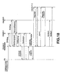
- the object manager controls up to the DoStart processing by using the above-described control processing in accordance with a sequence shown in Fig.16.
- connection information connection data
- the object manager is started up and loads the object A and the object B described in this connection information.
- the object manager loads the object A and the object B in accordance with a system command of the operating system.
- the object manager acquires and registers the object IDs of the objects A and B.
- the object manager starts the DoInit processing of the objects A and B in accordance with the observer ID acquired as described above and the selector number 0, and thus acquires and registers an entry (Control) as a subject and an entry (Connect) as an object from the objects A and B.
- the object manager starts the DoConnect processing of the object A, which is an observer, by using the registered entry (Connect), and connects the object B, which is a subject, to the object A.
- the inter-object connection is thus constructed on the basis of the connection information (connection data) and the object manager starts the DoStart processing of the objects A and B.
- Fig.17 is a time chart showing the sequence after the DoStart processing.
- the object A, the object B and other objects are started up by the DoStart processing at the object manager, these objects carry out the inter-object communications using the above-described Ready and Notify messages.
- the start-up causes the object A to send a Ready message to a Ready entry of the object B, and a Notify entry of the object A by the object B causes data to be sent to the object A from the object B. If no message is sent to the Ready entry of the object B from the object A during the processing of this data, the Notify entry of the object A by the object B is registered and a Ready entry of the object B by the object A causes data to be sent. Thus, in this inter-object communication, transmission of data which exceeds the data processing ability of the object A is prevented.
- Fig.18 is a time chart showing the sequence at plug-in, plug-out, and state change.
- the object manager On completion of the DoStop processing of all the objects, the object manager in this case sends a DoDisconnect command to the object A to disconnect the object A from the other objects and then starts the DoDestroy processing of the object A.
- the resource of the object A is thus opened and the registration of the object B carried out by the DoInit processing is canceled.
- the object manager executes the unloading in accordance with a system command of the operating system.
- the destructor of the required object is accessed, that is, in this case, the destructor of the object A is accessed, thereby canceling the registration of the object A carried out at the time of loading.
- the object manager opens the stack memory and the heap memory and thus completes the unloading of the object A.
- the object manager gives an instruction to load the object C in accordance with the connection information (connection data), and sequentially starts the DoInit, DoConnect and DoStart processing similarly to the processing described above with reference to Fig.16.
- connection information connection data
- This invention relates to inter-object (process) communication between objects (processes) and is adapted for realizing smooth inter-object communication.
- the inter-object communication that is, the input and output of data at the respective objects
- surrogate programs such as the object and the observer. Since data communication between the respective objects is realized by carrying out the predetermined procedure between the subject and the observer, as described above, the design of the structure between the respective objects is easily realized.
- the inter-object communication assumes that the respective objects operate in different memory spaces. Therefore, it is considered that the inter-object communication is realized by a technique in which data is copied from the object on the transmitting side to the object on the receiving side over the different memory spaces, or by a technique in which data is arranged on a shared memory which can be referred to from the respective objects (memory spaces).
- this invention realizes management of the data on the shared memory without requiring the users (objects) to manage the data.
- the number of times of reference to the shared memory (the number of references or the number of accesses) is measured, thereby managing the data on the shared memory.
- a technique of automatically measuring the number of times of reference is proposed in "More Effective (C++)," Scott Mayer, Addison-Wesley Publisher, pp.175-205. This invention extends such a technique as a technique for managing the data on the shared memory over different memory spaces.
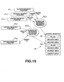
- Each user (object) is permitted to access a shared memory M by acquiring a shared memory pointer (hereinafter simply referred to as pointer). Specifically, as shown in Fig.19, the users who acquired pointers P11, P12 and P13, respectively, are permitted to access a first area M1 of the shared memory. The users who acquired pointers P21 and P22, respectively, are permitted to access a second area M2 of the shared memory. The data in the first area M1 of the shared memory M is shared (referable) by the users who acquired the pointers P11, P12 and P13, respectively. The data in the second area M2 of the shared memory is shared (referable) by the users who acquired the pointers P21 and P22, respectively.
- pointer shared memory pointer
- the permission of access (reference) to the respective areas based on the pointers P11, P12, P13, P21 and P22 is realized by holding the number of references (measured) by number-of-reference measuring objects RO1 and RO2.
- the number-of-reference measuring object is a number-of-access counting object for controlling the accesses to the shared memory by a plurality of objects on the basis of the number of pointers, which is the number of accesses generated in accordance with the accesses to the shared memory M by the objects.
- the number-of-reference measuring object is a communication management object for controlling the accesses to the shared memory M by a plurality of objects.
- the number-of-reference measuring object indicates the sole content on the shared memory and the number of pointers acquired by (or allocated to) the users who are referring to this content.
- the number of references by the users to a predetermined area on the shared memory is thus managed. For example, if the number of references measured by the number-of-reference measuring object is two or more, a plurality of users are accessing a predetermined area on the shared memory as indicated by the number-of-reference measuring object. If the number of references measured by the number-of-reference measuring object is zero, no users are accessing a predetermined area on the shared memory as indicated by the number-of-reference measuring object. As will be described later, if the number of references is zero, the number-of-reference measuring object is extinguished and the area which was indicated by the extinguished number-of-reference measuring object is caused to be an unused area.
- a shared memory is newly generated (or an area is secured on the shared memory), that is, the shared memory is newly accessed by a user.
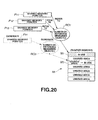
- a pointer P31 used by a user is prepared and a number-of-reference measuring object RO3 corresponding to the pointer P31 is prepared, as shown in Fig.20.
- the content indicated by the newly prepared number-of-reference measuring object RO3 is allocated to an unused area M3 on the shared memory M which is pooled by the system.
- the user who acquired the pointer P31 indicated by the number-of-reference measuring object RO3 can use the area M3 indicated by the number-of-reference measuring object RO3.
- such securing of a new area is carried out in the case where the new area is to be used as a data transmission buffer between objects in the inter-object communication.
- the predetermined area M3 on the shared memory M in which data is to be recorded is automatically allocated as a transmission buffer used between process communications in the inter-object communication.
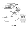
- a number-of-reference measuring object RO1 referred to by a pointer P11 which is to be extinguished is also referred to by other pointers P12 and P13, only the pointer P11 is extinguished. Then, the number of references measured by the number-of-reference measuring object RO1 is changed from three to two. Such a change in the number of references is equivalent to a change of the number-of-reference measuring object RO1.
- a number-of-reference measuring object RO2 is not referred to by any other pointer than a shared memory pointer P21 which is to be extinguished, that is, if the number of references measured by the number-of-reference measuring object RO2 is one, the pointer P21 which is to be extinguished and the number-of-reference measuring object RO2 which is referred to by the pointer P21 are extinguished.
- an area M2 which was indicated by the extinguished number-of-reference measuring object RO2 is returned to the system and is then considered to be an unused area.
- the area M1 indicated by the number-of-reference measuring object RO1 is still considered to be an area in use because the number of reference with respect to the area is not less than one.
- the number-of-reference measuring object is not less than two
- a plurality of users are using (i.e., referring to) a predetermined area on the shared memory corresponding to the number-of-reference measuring object, and if the number of references in the case of extinguishing a pointer (i.e., ending the reference) is not less than two, the number-of-reference measuring object is maintained, thus enabling protection of the use of (or reference to) the data by the other users.
- the predetermined area can be changed to an unused area.
- duplicating data is achieved simply by changingthe number-of-reference measuring object as the reference target (i.e., increasing or decreasing the number of references). Specifically, as shown in Fig.22, when duplicating data in a second area M2, if the data is to be duplicated for a new user, a new pointer P21 which refers to a second number-of-reference measuring object RO2 indicating the second area M2 is generated.
- the target of reference by a pointer P13 of the user is changed to the second number-of-reference measuring object RO2 indicating the second area M2.
- the number of references measured by the first number-of-reference measuring object RO1 indicating the first area M1 is reduced from three to two, and the number of references measured by the second number-of-reference measuring object RO2 is increased from one to three.
- Fig.23 the case of rewriting data recorded in a predetermined area on the shared memory will now be described.
- an area M2 in which data is to be rewritten is accessed only by the user (referrer) who is to rewrite the data, that is, if the number of references measured by a number-of-reference measuring object RO2 is one, free rewriting is permitted in the area M2 and therefore the data in the area M2 is directly rewritten.
- an area M1 in which data is to be rewritten is accessed by a plurality of users including the user who is to rewrite the data (that is, if the number of references measured by a number-of-reference measuring object RO1 is not less than two), rewriting the data will destroy the data for the other users and therefore an unused area M3 is allocated for rewriting.
- the unused area M3 is allocated and rewriting of the data is carried out in accordance with the following processing procedure.
- a new number-of-reference measuring object RO3 indicating (or allocated to) the unused area M3 is generated.
- the target of reference by a pointer P13 of the user who is to be rewrite the data is changed to the newly generated number-of-reference measuring object RO3, and the data is newly written into the area M3 indicated by the number-of-reference measuring object RO3.
- the number of references measured by the newly generated number-of-reference measuring object RO3 is one and the number of references measured by the original number-of-reference measuring object RO1 is reduced (in this example, from three to two).
- the generation of a number-of-reference measuring object and the change of a pointer to another number-of-reference measuring object as described above are automatically carried out by a system (control means) for monitoring the number of references measured by the number-of-reference measuring object. Therefore, the user who is to rewrite the data can rewrite the data, irrespective of the processing such as the generation of a number-of-reference measuring object and the change of a pointer to another number-of-reference measuring object (that is, without having to understand the processing).
- a user acquires a pointer P1, and by using the pointer P1, the user writes data which the user wants to transmit, into an area corresponding to the pointer P1.
- the area corresponding to the pointer P1 is an area M1 indicated by a number-of-reference measuring object RO1 which the pointer P1 refers to.
- the pointer P1 acquired for transmitting this data is handed to a subject of the object B, which is a surrogate program (transmission agent). Having received the pointer P1, the subject prepares a duplicate of the pointer P1 and a notification of the duplicate is sent to the object B (i.e., message passing is carried out). In this case, for example, the notification of the duplicate is sent to the object B together with attribute data including the ID of the shared memory or the like.
- message passing between the so-called subject and observer is realized by using a Notify message from the subject as described above, and is realized by the function (message communication function) to send a message accessing the shared memory M between information processing processes constructed in different memory spaces.
- the duplicate of the pointer P1 is prepared by the subject, one is added to the number of references measured by the number-of-reference measuring object RO1 on the transmitting side.
- the number of references measured by the number-of-reference measuring object RO1 is increased from three to four by the generation of the duplicate pointer P1.
- the observer as a surrogate program (reception agent) of the object B on the receiving side, receives the notification from the subject and stores a pointer P11. Moreover, on the basis of the ID of the shared memory or the like sent together with the pointer P11, the observer attaches to a memory M1 on the shared memory M indicated by the number-of-reference measuring object RO1 which the original pointer P1 of the pointer P11 refers to, from the memory space B side, by using a newly generated number-of-reference measuring object RO2.
- the observer prepares a pointer P2 for referring to the area M1 on the memory space B side in response to a request from the user (object B), and sends the pointer P2 to a number-of-reference measuring object RO3.
- the data in the area M1 which can be referred to by the object A
- the object B can also be referred to by the object B
- the inter-object communication is practically realized between the object A and the object B in the different memory spaces.
- the access to the shared memory by the object A is carried out on the assumption that the shared memory is also accessed by the object B.
- the opening of data means opening of the shared state of the shared memory from the state where the object A and the object B exist in the different memory spaces, respectively (as described with reference to Fig.24).
- a Ready message for requesting the next data is sent to the object A.
- the pointer P11 pointer P2 received from the object A is sought and it is checked whether the number of references measured by the number-of-reference measuring object RO2 corresponding to the sought pointer P11 is zero or not. If the number of references is zero, it is determined that the use at the object B is ended and the pointer P11 is sent back to the object A (subject) (that is, message passing is carried out).
- the corresponding pointer P1 is extinguished on the basis of the normal behavior (normal processing procedure). In this example, since the number of references measured by the corresponding number-of-reference measuring object RO1 is reduced from one to zero in response to the extinction of the pointer P1, the number-of-reference measuring object RO1 is extinguished.
- the data transfer processing and the like between the objects (users) existing in the different memory spaces are described above with reference to Figs.24 and 25.
- so-called subletting of data to a third object will be described, which is realized by applying the processing procedure as described above.
- the subletting of data to a third object applies to such a case that when a predetermined area M1 on the shared memory is shared by the objects A and B existing in different memory spaces, as shown in Fig.24, further opening (sharing) of the data to a third object is made possible.
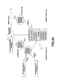
- the processing procedure for this so-called subletting of data to a third object can be basically achieved by combining the processing procedure of Fig.24 (data transfer processing) and Fig.25 (data opening processing). This processing procedure will now be described with reference to Fig.26.
- a user acquires a pointer P1, and by using the pointer P1, the user writes data which the user wants to send, into a corresponding area M1 on the shared memory M.
- the pointer P1 acquired for sending this data is handed to a subject of the object A.
- the subject Having received the pointer P1, the subject prepares duplicate of the pointer P1 and sends a notification of the duplicate to the object B (i.e., message passing is carried out).
- the notification is sent to the object B together with attribute data including the ID of the shared memory.
- An observer of the object B on the receiving side receives the notification from the subject and stores a pointer P11. Moreover, on the basis of the ID of the shared memory or the like sent together with the pointer P11, the observer attaches to the memory M1 on the shared memory M indicated by the number-of-reference measuring object RO1 which the original pointer P1 of the pointer P11 refers to, from the memory space B side, by using a newly generated number-of-reference measuring object RO2. Then, the observer prepares a pointer P2 for referring to this area on the memory space B side in response to a request from the user, and sends the pointer P2 to a number-of-reference measuring object RO3. The number of references measured by the number-of-reference measuring object RO1 is set to one. Thus, the result is equivalent to that the data in the area M1 is received by the user (object B).
- the object B sends the pointer P2 to the subject. Having received the pointer P2, the subject prepares a duplicate of the pointer P2 and sends a notification of the duplicate to a third object C (memory space C) as a subletting counterpart (i.e., message passing is carried out).
- the notification is sent to the object C together with attribute data including the ID of the shared memory.
- An observer of the object C on the receiving side receives the notification from the subject and stores a pointer P21. Through such processing, the number of references measured by the number-of-reference measuring object is propagated when the data sublet to the third object C. Therefore, the data in the area M1 is protected even when the data is sublet to the third object C.
- the data opening processing is carried out as follows.
- a Ready messages for requesting the next data is sent to the object B.
- the pointer P21 received from the object B is sought and it is checked whether the number of references measured by the corresponding number-of-reference measuring object RO3 is zero or not. If the number of references is zero, it is determined that the use at the object C is ended and the pointer P21 is sent back to the object B (that is, message passing is carried out).
- the corresponding pointer P2 is extinguished on the basis of the normal behavior (normal processing procedure).
- a Ready message is sent from the object B (observer) to the object A.
- the pointer P11 received from the object A is sought and it is checked whether the number of references measured by the corresponding number-of-reference measuring object RO2 is zero or not. If the number of references is zero, the pointer P11 is sent back to the object A (that is, message passing is carried out).
- the corresponding pointer P1 is extinguished on the basis of the normal behavior (normal processing procedure).
- the so-called data subletting processing to the third subject is carried out.
- the number of references measured by the number-of-reference measuring object is propagated when the data sublet to the third object C. Therefore, the data in the area M1 is protected even when the data is sublet to the third object C.
- data can be sent from one object (subject) to a plurality of objects (observers) by using the pointers as described above.
- the case of sending data from an object A on the transmitting side to a plurality of objects B and C on the receiving side, as shown in Fig.27, will now be described.
- the data is written into the shared memory and processing (data management) is carried out within the subject.
- the specific processing procedure is taken as follows.
- the user writes data into predetermined area M1, M2, M3 on the shared memory M, and sends to a subject pointers P11, P12, P21, P22, P23 referring to the areas M1, M2, M3 in which data is written.
- the subject On receiving the pointers P11, P12, P21, P22, P23, the subject first attempts to send data to observers of the objects B and C corresponding to the respective pointers P11, P12, P21, P22, P23. If reception is enabled on the receiving side (observer), the subject immediately sends the data. That is, a pointer is generated by the object on the receiving side and one is added to the number of references measured by the corresponding number-of-reference measuring object.
- reception is not enabled on the receiving side (observer)
- the subject enters a queue to every connection destination (receiving side). Then, when a Ready signal is received from the observer at which reception is enabled, the subject checks the queue from the observer which sent the Ready signal, and immediately sends data that is accumulated and should be sent to the object, if any.
- the quantity of the received data and the receiving timing can be varied in accordance with the application on the receiving side (object).
- An example of varying the receiving timing for image data at each object will now be described.
- image data is distributed to each of image processing objects which have different image processing contents such as an object for carrying out motion detection image processing (hereinafter referred to as motion detection object) and an object for recognizing a face image (hereinafter referred to as face recognition object).
- motion detection object an object for carrying out motion detection image processing
- face recognition object an object for recognizing a face image
- the motion detection object needs to receive one picture of image data once every two frames, while the face recognition object may receive one picture of image data once every 30 frames.
- object motion detection object or the face recognition object
- an image distribution object sends image data to a subject (every frame subject) for every frame processing.
- the subject receives parameters related to the quantity and synchronization of data transmission from an observer which is connected at the time of start-up of the system or the like.
- the subject carries out subsequent transmission in accordance with such parameters. Specifically, with respect to the observer of the motion detection object, the subject enters a queue in the data every other time, thereby carrying out transmission every other time.
- the-image data of the frame during the period when transmission is not carried out is annulled without carrying out any particular processing.
- the subject enters a queue in the data sent from the user once every 30 times, thus carrying out transmission once every 30 times.
- the quantity of the received data and the receiving timing (for example, processing cycle) can be varied in accordance with the application on the receiving side (object). Since such processing is realized by the subject and the object which are surrogate programs, the object need not be designed on the assumption of such processing and the independence of the object can be secured.
- the features of the present invention which are adapted as the embodiment are described above with reference to Figs.19 to 27.
- the present invention realizes smooth inter-object communication. Specifically, the following effects can be provided.
- the inter-object communication can be carried out at a high speed. Moreover, since data transmission between objects is carried out by sharing data on a shared memory, the time required for communication can be kept constant irrespective of the quantity of data.
- OS operating system
- Aperios provided by Sony Corporation may be considered.
- the OS is not limited to this and any general multi-process OS having the functions of message communication and shared memory may be employed.
- inter-object communication as the essential part of the present invention is applied to a robot device.
- the present invention is not limited to this embodiment.
- the present invention can also be applied to a device the operation of which is controlled by an object.
- the robot device 1 (Fig.1) having the above-described structure takes the four-legged type form by attaching legs as the moving unit 3 to the body 2 and is driven by the motor attached to the legs so as to walk with the four legs.
- the robot device 1 takes the wheeled type form by attaching wheels instead of the rear legs and is movable via the wheels.
- a necessary control command is outputted through the processing at the central processing unit 22, thus controlling the moving unit 3 and the like.
- the upper-layer software of object-oriented structure drives the various devices on the device driver layer, thus executing control of these devices.
- the virtual robot detects the components connected to the serial bus and notifies the design robot of the connection information (CPC connection information) indicating what robot component is connected in what order in the robot device 1 as a whole.
- the current form is specified in accordance with the device connected to the serial bus and the control target constituting the current form is specified.
- the software on the upper layer than the robot system software is updated in accordance with the connection information (CPC connection information) and the overall operation is controlled by appropriate software suitable for the form.
- the robot device 1 compares the design file described by appending a label to the group of constituent element information (CPC primitive location information) of the respective components for each form by the design robot of the robot system software, with the connection information (CPC connection information) notified of by the virtual robot, and selects an appropriate object suitable for the form, thus changing the form-dependent software based on this object (Figs.7 and 8).
- the appropriate software suitable for the form can be easily changed and the overall operation can be controlled.
- the upper-layer software is divided into the form-independent software which is independent of the form of the robot device and the form-dependent software which is dependent on the form, and only the form-dependent software is updated in the state where the data handled in a format independent of the form by the form-independent software is converted to a format corresponding to the form by the form-dependent software so as to be transmitted to and received from the robot system software.
- the software can be updated by simple processing.
- the virtual robot generates the constituent element information (CPCprimitive location information) using the description in a text data format (Figs.8 and 9) and the design file is described in a similar text data format. Therefore, it is easy to cope with the future increase of varying forms.
- the updating of the software is carried out as the object manager reconstructs the objects of the form-dependent software. That is, the object manager is notified of the connection information (connection data) giving an instruction to connect an object suitable for the current form, by the design robot at the start-up or the like, and the object designated by the connection information (connection data) is loaded (Fig.16).
- connection data connection information
- each object can be designed and the software can be constructed without considering any specific connection target.
- connection information connection data
- the software suitable for the form can be easily constructed.
- the software can be changed without re-compiling or re-linking. Therefore, in the robot device 1, the independence of the object can be significantly improved, compared with the conventional technique, and accordingly, the appropriate software suitable for free changes of the form can be provided easily and quickly.
- the inter-object communication can also be constructed between one object and a plurality of objects by so setting the connection information.
- connection information is the information specifying the format of data to be communicated with a subject
- the object manager can specify the corresponding object ID and selector number in accordance with the connection information (connection data) and easily construct the inter-object communication.
- the design robot selects and provides connection information from the design file having a plurality of pieces of connection information recorded therein to the object manager, it is possible to easily construct the software corresponding to various forms, when necessary, by so setting the design.
- connection information (connection data) is described in a text data format, it can be easily changed in various manners.
- connection information CPC connection information
- the design robot compares this connection information (CPC connection information) with the design file and thus generates connection information (connection data) relating to the changed form.
- connection information connection data
- the object manager unloads an object which has become unnecessary because of the change of the form, and loads an object which has become necessary because of the change of the form, thus reconstructing the objects constituting the form-dependent software.
- these objects are connected to enable inter-object communication by the connection information (connection data) and the form-dependent software is thus updated.
- the form-dependent software can be updated, when necessary, to construct the software suitable for the form. It is also possible to apply this change of the software to switching of the power consumption mode. Moreover, the present invention enables smooth inter-object communication and high-speed processing.
- the robot device used as an embodiment of the present invention is not limited to a device having an appearance as shown in Fig.1.
- the robot device 1 may also have an appearance/shape which is more like that of a certain animal, as shown in Fig.28.
- the parts corresponding to those in Fig.1 are denoted by the same numerals.
Landscapes
- Engineering & Computer Science (AREA)
- Theoretical Computer Science (AREA)
- Software Systems (AREA)
- Physics & Mathematics (AREA)
- General Engineering & Computer Science (AREA)
- General Physics & Mathematics (AREA)
- Biophysics (AREA)
- Evolutionary Computation (AREA)
- Health & Medical Sciences (AREA)
- Life Sciences & Earth Sciences (AREA)
- Artificial Intelligence (AREA)
- Biomedical Technology (AREA)
- Automation & Control Theory (AREA)
- Computational Linguistics (AREA)
- Data Mining & Analysis (AREA)
- Robotics (AREA)
- General Health & Medical Sciences (AREA)
- Molecular Biology (AREA)
- Computing Systems (AREA)
- Mathematical Physics (AREA)
- Quality & Reliability (AREA)
- Manufacturing & Machinery (AREA)
- Manipulator (AREA)
- Numerical Control (AREA)
Abstract
Description


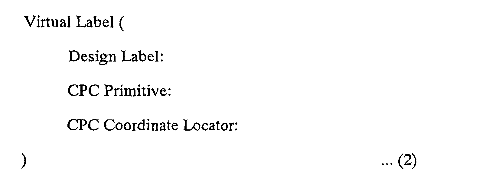


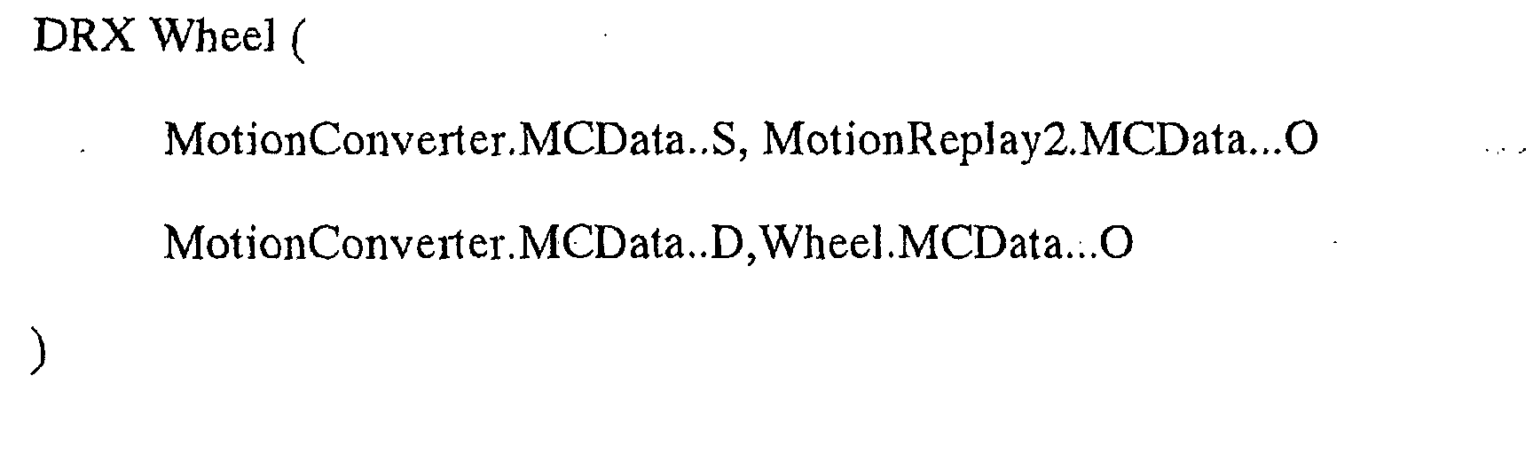


Claims (25)
- An information processing device comprising control means having a plurality of information processing processes and adapted for carrying out control processing based on inter-process communication carried out between the information processing processes, the control means controlling accesses by the plurality of information processing processes to a shared memory shared by the plurality of information processing processes and thus carrying out inter-process communication.
- The information processing device as claimed in claim 1, wherein the information processing processes are made up of programs prepared on the basis of an object-oriented system.
- The information processing device as claimed in claim 1, wherein as the control means, in the inter-process communication, controls accesses by the plurality of information processing processes to data in the same area on the shared memory, the data is shared by the plurality of information processes.
- The information processing device as claimed in claim 3, wherein as the control means, in the inter-process communication, automatically allocates the same area on the shared memory in which data is to be recorded, as a transmission buffer used for the inter-process communication.
- The information processing device as claimed in claim 1, wherein the control means controls the accesses by the plurality of information processing processes to the shared memory by using a communication management process.
- The information processing device as claimed in claim 1, wherein the control means transmits a message for accessing the shared memory by the information processing processes constituted in different memory spaces, and controls the accesses to the shared memory by the plurality of information processing processes on the basis of the message.
- The information processing device as claimed in claim 1, wherein the control means controls the accesses to the shared memory by the plurality of information processing processes on the basis of the number of accesses to the shared memory by the information processing processes.
- The information processing device as claimed in claim 7, wherein the control means generates pointers in accordance with the accesses to the shared memory by the information processing processes and controls the accesses to the shared memory by the plurality of information processing processes on the basis of the number of pointers as the number of accesses.
- The information processing device as claimed in claim 8, wherein the control means has a number-of-access measuring process for measuring the number of accesses and enables dynamic change of a communication counterpart in the inter-process communication, and
the control means controls the accesses to the shared memory by the plurality of information processing processes on the basis of the number of accesses measured by the number-of-access measuring process. - The information processing device as claimed in claim 1, wherein the plurality of information processing processes are constituted in different memory spaces, respectively, and
the accesses to the shared memory by the plurality of information processing processes are made over the different memory spaces. - The information processing device as claimed in claim 1, wherein the control means controls the access to the shared memory on the basis of the processing cycle of the information processing process on the receiving side.
- The information processing device as claimed in claim 1, wherein the control means generates a queue for the access to the shared memory on the basis of the load on the information processing process on the receiving side, and controls the access to the shared memory in accordance with the queue.
- An information processing method having a plurality of information processing processes and adapted for carrying out control processing based on inter-process communication carried out between the information processing processes, the information processing method comprising controlling accesses by the plurality of information processing processes to a shared memory shared by the plurality of information processing processes and thus carrying out inter-process communication.
- A robot device comprising:output means for expressing a motion; andcontrol means having a plurality of information processing processes and adapted for carrying out control processing of the output means based on inter-process communication carried out between the information processing processes, the control means controlling accesses by the plurality of information processing processes to a shared memory shared by the plurality of information processing processes and thus carrying out inter-process communication.
- The robot device as claimed in claim 14, wherein the information processing processes are made up of programs prepared on the basis of an object-oriented system.
- The robot device as claimed in claim 14, wherein as the control means, in the inter-process communication, controls accesses by the plurality of information processing processes to data in the same area on the shared memory, the data is shared by the plurality of information processes.
- The robot device as claimed in claim 16, wherein as the control means, in the inter-process communication, automatically allocates the same area on the shared memory in which data is to be recorded, as a transmission buffer used for the inter-process communication.
- The robot device as claimed in claim 14, wherein the control means controls the accesses by the plurality of information processing processes to the shared memory by using a communication management process.
- The robot device as claimed in claim 14, wherein the control means transmits a message for accessing the shared memory by the information processing processes constituted in different memory spaces, and controls the accesses to the shared memory by the plurality of information processing processes on the basis of the message.
- The robot device as claimed in claim 14, wherein the control means controls the accesses to the shared memory by the plurality of information processing processes on the basis of the number of accesses to the shared memory by the information processing processes.
- The robot device as claimed in claim 20, wherein the control means generates pointers in accordance with the accesses to the shared memory by the information processing processes and controls the accesses to the shared memory by the plurality of information processing processes on the basis of the number of pointers as the number of accesses.
- The robot device as claimed in claim 21, wherein the control means has a number-of-access measuring process for measuring the number of accesses and enables dynamic change of a communication counterpart in the inter-process communication, and
the control means controls the accesses to the shared memory by the plurality of information processing processes on the basis of the number of accesses measured by the number-of-access measuring process. - The robot device as claimed in claim 14, wherein the plurality of information processing processes are constituted in different memory spaces, respectively, and
the accesses to the shared memory by the plurality of information processing processes are made over the different memory spaces. - The robot device as claimed in claim 14, wherein the control means controls the access to the shared memory on the basis of the processing cycle of the information processing process on the receiving side.
- The robot device as claimed in claim 14, wherein the control means generates a queue for the access to the shared memory on the basis of the load on the information processing process on the receiving side, and controls the access to the shared memory in accordance with the queue.
Applications Claiming Priority (3)
| Application Number | Priority Date | Filing Date | Title |
|---|---|---|---|
| JP2000247021 | 2000-08-16 | ||
| JP2000247021A JP2002063038A (en) | 2000-08-16 | 2000-08-16 | Information processing apparatus, information processing method, and robot apparatus |
| PCT/JP2001/007067 WO2002015009A1 (en) | 2000-08-16 | 2001-08-16 | Information processing device, information processing method, and robot apparatus |
Publications (2)
| Publication Number | Publication Date |
|---|---|
| EP1310870A1 true EP1310870A1 (en) | 2003-05-14 |
| EP1310870A4 EP1310870A4 (en) | 2008-07-02 |
Family
ID=18737199
Family Applications (1)
| Application Number | Title | Priority Date | Filing Date |
|---|---|---|---|
| EP01956926A Withdrawn EP1310870A4 (en) | 2000-08-16 | 2001-08-16 | INFORMATION PROCESSING DEVICE AND METHOD AND ASSOCIATED ROBOT |
Country Status (5)
| Country | Link |
|---|---|
| US (1) | US7228201B2 (en) |
| EP (1) | EP1310870A4 (en) |
| JP (1) | JP2002063038A (en) |
| CN (1) | CN1270238C (en) |
| WO (1) | WO2002015009A1 (en) |
Families Citing this family (7)
| Publication number | Priority date | Publication date | Assignee | Title |
|---|---|---|---|---|
| JP2002342759A (en) * | 2001-01-30 | 2002-11-29 | Nec Corp | System and method for providing information and its program |
| JP4458929B2 (en) * | 2003-07-16 | 2010-04-28 | キヤノン株式会社 | Inter-program communication apparatus, inter-program communication method, computer-readable recording medium, and program |
| US7403949B2 (en) * | 2005-08-17 | 2008-07-22 | International Business Machines Corporation | Elimination of redundant objects in storage systems |
| US8301421B2 (en) * | 2006-03-31 | 2012-10-30 | Energid Technologies | Automatic control system generation for robot design validation |
| US8392921B2 (en) * | 2009-12-18 | 2013-03-05 | Electronics And Telecommunications Research Institute | Apparatus and method of coordinating operation action of robot software component |
| KR101269024B1 (en) | 2009-12-18 | 2013-05-29 | 한국전자통신연구원 | Apparatus and method of coordinating an operation action of robot software component |
| JP6510761B2 (en) * | 2014-04-08 | 2019-05-08 | 川崎重工業株式会社 | Data acquisition system and method |
Family Cites Families (10)
| Publication number | Priority date | Publication date | Assignee | Title |
|---|---|---|---|---|
| US5652885A (en) * | 1993-05-25 | 1997-07-29 | Storage Technology Corporation | Interprocess communications system and method utilizing shared memory for message transfer and datagram sockets for message control |
| JPH11120009A (en) | 1997-10-14 | 1999-04-30 | Toshiba Tec Corp | Inter-process communication controller |
| JP2000148577A (en) | 1998-11-09 | 2000-05-30 | Fujitsu Ltd | Access control method and access control device |
| US6477580B1 (en) * | 1999-08-31 | 2002-11-05 | Accenture Llp | Self-described stream in a communication services patterns environment |
| US6606660B1 (en) * | 1999-08-31 | 2003-08-12 | Accenture Llp | Stream-based communication in a communication services patterns environment |
| US6615253B1 (en) * | 1999-08-31 | 2003-09-02 | Accenture Llp | Efficient server side data retrieval for execution of client side applications |
| US6636242B2 (en) * | 1999-08-31 | 2003-10-21 | Accenture Llp | View configurer in a presentation services patterns environment |
| US6640249B1 (en) * | 1999-08-31 | 2003-10-28 | Accenture Llp | Presentation services patterns in a netcentric environment |
| US6289382B1 (en) * | 1999-08-31 | 2001-09-11 | Andersen Consulting, Llp | System, method and article of manufacture for a globally addressable interface in a communication services patterns environment |
| US6976216B1 (en) * | 2000-11-17 | 2005-12-13 | Streamzap, Inc. | Computer system with remote key press events directed to a first application program and local key press events directed to a second application program |
-
2000
- 2000-08-16 JP JP2000247021A patent/JP2002063038A/en not_active Withdrawn
-
2001
- 2001-08-16 EP EP01956926A patent/EP1310870A4/en not_active Withdrawn
- 2001-08-16 WO PCT/JP2001/007067 patent/WO2002015009A1/en not_active Ceased
- 2001-08-16 US US10/110,497 patent/US7228201B2/en not_active Expired - Fee Related
- 2001-08-16 CN CNB018026958A patent/CN1270238C/en not_active Expired - Fee Related
Also Published As
| Publication number | Publication date |
|---|---|
| EP1310870A4 (en) | 2008-07-02 |
| WO2002015009A1 (en) | 2002-02-21 |
| US20030040839A1 (en) | 2003-02-27 |
| US7228201B2 (en) | 2007-06-05 |
| CN1388927A (en) | 2003-01-01 |
| CN1270238C (en) | 2006-08-16 |
| JP2002063038A (en) | 2002-02-28 |
Similar Documents
| Publication | Publication Date | Title |
|---|---|---|
| US7388879B2 (en) | Communication device and communication method network system and robot apparatus | |
| CN100511130C (en) | Arithmetic processing device, object-to-object communication method | |
| Vaughan et al. | Reusable robot software and the player/stage project | |
| US8196154B2 (en) | Copying workload files to a virtual disk | |
| JP3339482B2 (en) | Distributed debugging apparatus, debugging method, and recording medium recording control program | |
| US6728598B2 (en) | Arithmetic processing device, inter-object communication method, and robot | |
| JPH0683746A (en) | Distributed information processing system | |
| US20140297775A1 (en) | Method and system for providing remote direct memory access to virtual machines | |
| CN110524543A (en) | An industrial robot control device and system based on control integration | |
| JPH1040196A5 (en) | ||
| US7228201B2 (en) | Information processing device, information processing method, and robot apparatus | |
| WO1998041952A1 (en) | Image generating device and information storing medium | |
| CN101243396A (en) | Method and apparatus for supporting universal serial bus devices in a virtualized environment | |
| WO2002052410A1 (en) | Method of manipulating a distributed system of computer-implemented objects | |
| Armand | Give a process to your drivers | |
| JP2002189608A (en) | Communication device and communication method, information processing system, program creation method, network system, and robot device | |
| JP2003233502A (en) | Arithmetic processing unit and management method of communication between objects | |
| KR100853426B1 (en) | Device manager and management method of humanoid robot | |
| CN121722277A (en) | A robot visualization and interactive control method, device, equipment, and storage medium | |
| Dixon et al. | Self-adaptive software composed of port-based agents | |
| Arbuckle et al. | RECIPE–A System for Building Extensible, Run-time Configurable, Image Processing Systems | |
| JPH01134508A (en) | Robot control system | |
| JP2000215180A (en) | Data communication device, system and method | |
| Yu | A concurrent real-time autonomous mobile robot programming system | |
| Arbuckle et al. | A Reconfigurable Image Capture and Image Processing System for Autonomous Robots: A Proposal |
Legal Events
| Date | Code | Title | Description |
|---|---|---|---|
| PUAI | Public reference made under article 153(3) epc to a published international application that has entered the european phase |
Free format text: ORIGINAL CODE: 0009012 |
|
| 17P | Request for examination filed |
Effective date: 20020501 |
|
| AK | Designated contracting states |
Designated state(s): AT BE CH CY DE DK ES FI FR GB GR IE IT LI LU MC NL PT SE TR |
|
| RBV | Designated contracting states (corrected) |
Designated state(s): AT BE CH DE FR GB LI |
|
| A4 | Supplementary search report drawn up and despatched |
Effective date: 20080604 |
|
| RIC1 | Information provided on ipc code assigned before grant |
Ipc: G06F 12/02 20060101ALI20080529BHEP Ipc: B25J 13/00 20060101ALN20080529BHEP Ipc: G06F 9/46 20060101AFI20020226BHEP Ipc: G06F 9/44 20060101ALI20080529BHEP Ipc: G06N 3/00 20060101ALI20080529BHEP |
|
| 17Q | First examination report despatched |
Effective date: 20081128 |
|
| STAA | Information on the status of an ep patent application or granted ep patent |
Free format text: STATUS: THE APPLICATION IS DEEMED TO BE WITHDRAWN |
|
| 18D | Application deemed to be withdrawn |
Effective date: 20100330 |