EP1310744A2 - Cooling system for cooling indoor air - Google Patents
Cooling system for cooling indoor air Download PDFInfo
- Publication number
- EP1310744A2 EP1310744A2 EP02396165A EP02396165A EP1310744A2 EP 1310744 A2 EP1310744 A2 EP 1310744A2 EP 02396165 A EP02396165 A EP 02396165A EP 02396165 A EP02396165 A EP 02396165A EP 1310744 A2 EP1310744 A2 EP 1310744A2
- Authority
- EP
- European Patent Office
- Prior art keywords
- cooling
- fan
- air
- vaporizer
- compressor cooler
- Prior art date
- Legal status (The legal status is an assumption and is not a legal conclusion. Google has not performed a legal analysis and makes no representation as to the accuracy of the status listed.)
- Granted
Links
Images
Classifications
-
- F—MECHANICAL ENGINEERING; LIGHTING; HEATING; WEAPONS; BLASTING
- F24—HEATING; RANGES; VENTILATING
- F24F—AIR-CONDITIONING; AIR-HUMIDIFICATION; VENTILATION; USE OF AIR CURRENTS FOR SCREENING
- F24F1/00—Room units for air-conditioning, e.g. separate or self-contained units or units receiving primary air from a central station
- F24F1/02—Self-contained room units for air-conditioning, i.e. with all apparatus for treatment installed in a common casing
- F24F1/022—Self-contained room units for air-conditioning, i.e. with all apparatus for treatment installed in a common casing comprising a compressor cycle
- F24F1/027—Self-contained room units for air-conditioning, i.e. with all apparatus for treatment installed in a common casing comprising a compressor cycle mounted in wall openings, e.g. in windows
-
- F—MECHANICAL ENGINEERING; LIGHTING; HEATING; WEAPONS; BLASTING
- F24—HEATING; RANGES; VENTILATING
- F24F—AIR-CONDITIONING; AIR-HUMIDIFICATION; VENTILATION; USE OF AIR CURRENTS FOR SCREENING
- F24F13/00—Details common to, or for air-conditioning, air-humidification, ventilation or use of air currents for screening
- F24F13/08—Air-flow control members, e.g. louvres, grilles, flaps or guide plates
- F24F13/10—Air-flow control members, e.g. louvres, grilles, flaps or guide plates movable, e.g. dampers
- F24F13/14—Air-flow control members, e.g. louvres, grilles, flaps or guide plates movable, e.g. dampers built up of tilting members, e.g. louvre
- F24F13/1413—Air-flow control members, e.g. louvres, grilles, flaps or guide plates movable, e.g. dampers built up of tilting members, e.g. louvre using more than one tilting member, e.g. with several pivoting blades
-
- F—MECHANICAL ENGINEERING; LIGHTING; HEATING; WEAPONS; BLASTING
- F24—HEATING; RANGES; VENTILATING
- F24F—AIR-CONDITIONING; AIR-HUMIDIFICATION; VENTILATION; USE OF AIR CURRENTS FOR SCREENING
- F24F11/00—Control or safety arrangements
- F24F11/0001—Control or safety arrangements for ventilation
- F24F2011/0006—Control or safety arrangements for ventilation using low temperature external supply air to assist cooling
-
- Y—GENERAL TAGGING OF NEW TECHNOLOGICAL DEVELOPMENTS; GENERAL TAGGING OF CROSS-SECTIONAL TECHNOLOGIES SPANNING OVER SEVERAL SECTIONS OF THE IPC; TECHNICAL SUBJECTS COVERED BY FORMER USPC CROSS-REFERENCE ART COLLECTIONS [XRACs] AND DIGESTS
- Y02—TECHNOLOGIES OR APPLICATIONS FOR MITIGATION OR ADAPTATION AGAINST CLIMATE CHANGE
- Y02B—CLIMATE CHANGE MITIGATION TECHNOLOGIES RELATED TO BUILDINGS, e.g. HOUSING, HOUSE APPLIANCES OR RELATED END-USER APPLICATIONS
- Y02B30/00—Energy efficient heating, ventilation or air conditioning [HVAC]
- Y02B30/54—Free-cooling systems
Definitions
- the invention relates to a cooling system for cooling indoor air, the system comprising a compressor cooler which uses outdoor air as cooling air, a fan vaporizer which circulates indoor air and is connected to the compressor cooler, and a fan for free cooling by means of outdoor air.
- Cooling system of this kind is used particularly in premises where there are several heat-producing devices. Such premises are often small, too. Typical applications for these systems are GSM centres, for example.
- the prior art systems always comprise several component units placed apart from one another because compressor coolers and fan vaporizers may be supplied by different manufacturers, and thus these need to be connected to one another with suitable pipes.
- the devices are often placed on the floor, which wastes floor space, or in equipment racks, which are placed on the floor and would be needed for other devices.
- an air cooling device When an air cooling device is on the floor, its air intake is usually arranged through the wall at the location of the device. In that case the air inlet outside the building may be close to the ground surface and is thus prone to vandalism.
- Several separate devices also require several fresh air inlets.
- the cooling capacity of the prior art cooling systems is modest in relation to the space they require and the number of inlets needed in the wall of the space to be cooled.
- the object of the invention is to improve the system described at the beginning so as to solve the above-mentioned problems. This is achieved by a system of the invention which is characterized in that the compressor cooler, fan vaporizer and fan for free cooling are arranged in the same casing as a single cooling unit.
- the fan vaporizer used in this unit is preferably a cassette-type component, i.e. a 'cassette assembly'.
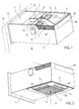
- the cooling unit of the invention formed as a single packet is small enough to be mounted in one inlet provided through the outer wall, e.g. above the doors of GSM antenna boxes, in which case it is difficult for vandals to damage it. Neither does it take up space in equipment racks.
- the fan vaporizer By combining the fan vaporizer and the compressor cooler, the fan vaporizer can be provided with a large front surface, in which case a high mechanical cooling capacity is achieved with respect to the volume of the cooling unit. Air enters the fan vaporizer vertically and exits horizontally.
- the cooling unit can process large amounts of air because, according to the invention, the fresh air of free cooling connected to the unit can be guided past the compressor cooler and fan vaporizer, and mechanical cooling can be used at the same time. In that case the device may be provided with stepless control between free cooling and mechanical cooling.
- a cooling unit of the invention consists of a single assembly which is arranged in the same casing and mounted in an opening provided though an outer wall W.
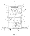
- the unit comprises a compressor cooler 1 at the end that will be mounted through the outer wall W of the building, a fan for free cooling in the middle of the unit at its one edge and a cassette-type fan vaporizer 3 at the end of the unit which protrudes from the wall W.
- the flow channel is connected to a fan space 7 functioning as a location for the fan 2 via a gate valve 6 and to the space R to be cooled via a grid 8 provided at the end of the cooling unit.
- the fan vaporizer 3 comprises a sound-proof steel cover 10, inside of which there is typically a round cooling (or heating) radiator 11. In the middle of the radiator there is a fan 12 which sucks air from the space R to be cooled through its inlet grid 12 provided on the same level with the lower surface of the cooling unit and a filter (not shown) arranged behind the inlet grid. After this, the fan 12 blows the air through the radiator 11, which cools it. Then the fan 12 blows the air back to the space R through flow openings 14 provided on the sides of the fan vaporizer 3 and simultaneously on the lower surface of the cooling unit.
- a round cooling (or heating) radiator 11 In the middle of the radiator there is a fan 12 which sucks air from the space R to be cooled through its inlet grid 12 provided on the same level with the lower surface of the cooling unit and a filter (not shown) arranged behind the inlet grid. After this, the fan 12 blows the air through the radiator 11, which cools it. Then the fan 12 blows the air back
- the compressor cooler 1 is connected to the fan vaporizer 3 with pipes 14. Vaporizable cooling medium coolde by the compressor cooler 1 flows in the pipes 14 to enhance the function of the fan vaporizer 3.
- the compressor cooler 1 and the fan vaporizer 3 provide together mechanical cooling.
- the function of the compressor cooler 1 is not described in greater detail here because it is well known in the field (as well as the fan vaporizer described above). Briefly, using outdoor air as a cooler, the compressor cooler 1 enhances the function of the fan vaporizer 3 which circulates and cools indoor air.
- an exhaust air flow channel 15 in the upper part of the cooling unit next to the flow channel 5 for fresh air, from which the exhaust air flow channel 15 is separated.
- the exhaust air flow channel 15 is connected to the space R to be cooled via one grid 18 in the upper part of one side of the cooling unit and to an exhaust air outlet 17 via a gate valve 16 provided in the middle of the channel 15.
- the cooling unit can be used as follows, for example:
Landscapes
- Engineering & Computer Science (AREA)
- Chemical & Material Sciences (AREA)
- Combustion & Propulsion (AREA)
- Mechanical Engineering (AREA)
- General Engineering & Computer Science (AREA)
- Devices That Are Associated With Refrigeration Equipment (AREA)
- Other Air-Conditioning Systems (AREA)
Abstract
Description
Claims (3)
- A cooling apparatus for cooling inside air, the apparatus comprising a compressor cooler (1) which uses outdoor air as cooling air, a fan vaporizer (3) which circulates indoor air and is connected to the compressor cooler, and a fan (2) for free cooling by means of outdoor air, characterized in that the compressor cooler (1), fan vaporizer (3) and fan (2) for free cooling are arranged in the same casing as a single cooling unit.
- A system according to claim 1, characterized in that the fan vaporizer (3) is a cassette type unit.
- A system according to claim 1 or 2, characterized in that the fan (2) for free cooling can be controlled independently of the compressor cooler (1) and the fan vaporizer (3).
Applications Claiming Priority (2)
| Application Number | Priority Date | Filing Date | Title |
|---|---|---|---|
| FI20012177A FI120705B (en) | 2001-11-09 | 2001-11-09 | Cooling arrangement for cooling indoor air |
| FI20012177 | 2001-11-09 |
Publications (3)
| Publication Number | Publication Date |
|---|---|
| EP1310744A2 true EP1310744A2 (en) | 2003-05-14 |
| EP1310744A3 EP1310744A3 (en) | 2005-08-10 |
| EP1310744B1 EP1310744B1 (en) | 2007-01-10 |
Family
ID=8562222
Family Applications (1)
| Application Number | Title | Priority Date | Filing Date |
|---|---|---|---|
| EP02396165A Expired - Lifetime EP1310744B1 (en) | 2001-11-09 | 2002-11-07 | Cooling system for cooling indoor air |
Country Status (2)
| Country | Link |
|---|---|
| EP (1) | EP1310744B1 (en) |
| FI (1) | FI120705B (en) |
Cited By (3)
| Publication number | Priority date | Publication date | Assignee | Title |
|---|---|---|---|---|
| WO2005116530A1 (en) * | 2004-05-28 | 2005-12-08 | Omas S.R.L. | Portable air conditioner |
| EP1816408A1 (en) * | 2006-02-07 | 2007-08-08 | Emerson Network Power S.R.L. | Conditioning device of the free cooling type |
| CN102538080A (en) * | 2012-01-05 | 2012-07-04 | 北京德能恒信科技有限公司 | Integral energy-saving cooling air conditioner device |
Family Cites Families (5)
| Publication number | Priority date | Publication date | Assignee | Title |
|---|---|---|---|---|
| US4524588A (en) * | 1983-11-21 | 1985-06-25 | Amana Refrigeration, Inc. | Air conditioner with improved fresh air path |
| US5447037A (en) * | 1994-03-31 | 1995-09-05 | American Standard Inc. | Economizer preferred cooling control |
| IT239243Y1 (en) * | 1995-07-27 | 2001-02-26 | Olimpia Srl | TRANSFERABLE TYPE PERFECTED CONDITIONER |
| US6038879A (en) * | 1995-08-08 | 2000-03-21 | Yvon Turcotte | Combined air exchange and air conditioning unit |
| US5970723A (en) * | 1996-03-05 | 1999-10-26 | Kinkel; Stephen W. | Heating and cooling unit |
-
2001
- 2001-11-09 FI FI20012177A patent/FI120705B/en not_active IP Right Cessation
-
2002
- 2002-11-07 EP EP02396165A patent/EP1310744B1/en not_active Expired - Lifetime
Cited By (4)
| Publication number | Priority date | Publication date | Assignee | Title |
|---|---|---|---|---|
| WO2005116530A1 (en) * | 2004-05-28 | 2005-12-08 | Omas S.R.L. | Portable air conditioner |
| EP1816408A1 (en) * | 2006-02-07 | 2007-08-08 | Emerson Network Power S.R.L. | Conditioning device of the free cooling type |
| CN102538080A (en) * | 2012-01-05 | 2012-07-04 | 北京德能恒信科技有限公司 | Integral energy-saving cooling air conditioner device |
| CN102538080B (en) * | 2012-01-05 | 2016-07-06 | 北京德能恒信科技有限公司 | A kind of Integral energy-saving cooling air conditioner device |
Also Published As
| Publication number | Publication date |
|---|---|
| EP1310744A3 (en) | 2005-08-10 |
| FI120705B (en) | 2010-01-29 |
| EP1310744B1 (en) | 2007-01-10 |
| FI20012177A0 (en) | 2001-11-09 |
Similar Documents
| Publication | Publication Date | Title |
|---|---|---|
| US5533357A (en) | Air conditioning apparatus | |
| US20190219277A1 (en) | Air conditioner | |
| US20100041327A1 (en) | Apparatus, system and method for air conditioning using fans located under flooring | |
| US20230250973A1 (en) | Packaged terminal air conditioner (ptac) with an integrated energy recovery ventilator (erv) or heat recovery ventilator (hrv) | |
| KR20060050949A (en) | Ventilation and air conditioning | |
| EP3272562A1 (en) | Air conditioner for vehicle | |
| WO2002077535A1 (en) | Air conditioner and method of installing the air conditioner | |
| JPH02213624A (en) | Thermal exchange unit of air-conditioner | |
| JP2005172309A (en) | Blower and air conditioning system for room | |
| CN112234803A (en) | Frequency converter, refrigeration system and control method thereof | |
| GB2519308A (en) | Evaporative Cooler Apparatus and Method | |
| KR101470317B1 (en) | Outdoor booth having air conditioner | |
| EP1310744B1 (en) | Cooling system for cooling indoor air | |
| US7886555B2 (en) | Mobile communications shelter with air distribution assembly | |
| KR20220071491A (en) | Control method of wall-type data center air conditioning system for energy saving | |
| KR20180100073A (en) | Hybrid air conditioning system and automatic control method of the hybrid air conditioning system | |
| JP2009257644A (en) | Heat exchange apparatus and heating element storage apparatus using the same | |
| CN1423918A (en) | Device for cooling of heat-generating units | |
| JPH06331180A (en) | Outdoor unit for air conditioner | |
| JP3449344B2 (en) | Air conditioning system with outside air processing function | |
| JPS5849022Y2 (en) | Outdoor units such as cooling equipment | |
| JPH0633335Y2 (en) | Air conditioners in stores with showcases | |
| CN223499674U (en) | A ducted air conditioner and air conditioning system | |
| JPS63306329A (en) | Air-conditioning machine for underfloor air-conditioning system | |
| US20250198646A1 (en) | Supplemental Heat Source in Self-Contained Heat Pump Room Conditioning Units |
Legal Events
| Date | Code | Title | Description |
|---|---|---|---|
| PUAI | Public reference made under article 153(3) epc to a published international application that has entered the european phase |
Free format text: ORIGINAL CODE: 0009012 |
|
| AK | Designated contracting states |
Designated state(s): AT BE BG CH CY CZ DE DK EE ES FI FR GB GR IE IT LI LU MC NL PT SE SK TR |
|
| AX | Request for extension of the european patent |
Extension state: AL LT LV MK RO SI |
|
| PUAL | Search report despatched |
Free format text: ORIGINAL CODE: 0009013 |
|
| AK | Designated contracting states |
Kind code of ref document: A3 Designated state(s): AT BE BG CH CY CZ DE DK EE ES FI FR GB GR IE IT LI LU MC NL PT SE SK TR |
|
| AX | Request for extension of the european patent |
Extension state: AL LT LV MK RO SI |
|
| 17P | Request for examination filed |
Effective date: 20060117 |
|
| GRAP | Despatch of communication of intention to grant a patent |
Free format text: ORIGINAL CODE: EPIDOSNIGR1 |
|
| AKX | Designation fees paid |
Designated state(s): GB IT SE |
|
| REG | Reference to a national code |
Ref country code: DE Ref legal event code: 8566 |
|
| GRAS | Grant fee paid |
Free format text: ORIGINAL CODE: EPIDOSNIGR3 |
|
| GRAA | (expected) grant |
Free format text: ORIGINAL CODE: 0009210 |
|
| AK | Designated contracting states |
Kind code of ref document: B1 Designated state(s): GB IT SE |
|
| REG | Reference to a national code |
Ref country code: GB Ref legal event code: FG4D |
|
| REG | Reference to a national code |
Ref country code: SE Ref legal event code: TRGR |
|
| PLBE | No opposition filed within time limit |
Free format text: ORIGINAL CODE: 0009261 |
|
| STAA | Information on the status of an ep patent application or granted ep patent |
Free format text: STATUS: NO OPPOSITION FILED WITHIN TIME LIMIT |
|
| 26N | No opposition filed |
Effective date: 20071011 |
|
| PGFP | Annual fee paid to national office [announced via postgrant information from national office to epo] |
Ref country code: GB Payment date: 20211118 Year of fee payment: 20 Ref country code: SE Payment date: 20211117 Year of fee payment: 20 |
|
| PGFP | Annual fee paid to national office [announced via postgrant information from national office to epo] |
Ref country code: IT Payment date: 20211118 Year of fee payment: 20 |
|
| REG | Reference to a national code |
Ref country code: GB Ref legal event code: PE20 Expiry date: 20221106 |
|
| REG | Reference to a national code |
Ref country code: SE Ref legal event code: EUG |
|
| PG25 | Lapsed in a contracting state [announced via postgrant information from national office to epo] |
Ref country code: GB Free format text: LAPSE BECAUSE OF EXPIRATION OF PROTECTION Effective date: 20221106 |