EP1310728A1 - A process for making a container for pressurized fluids, and corresponding container - Google Patents
A process for making a container for pressurized fluids, and corresponding container Download PDFInfo
- Publication number
- EP1310728A1 EP1310728A1 EP20020023453 EP02023453A EP1310728A1 EP 1310728 A1 EP1310728 A1 EP 1310728A1 EP 20020023453 EP20020023453 EP 20020023453 EP 02023453 A EP02023453 A EP 02023453A EP 1310728 A1 EP1310728 A1 EP 1310728A1
- Authority
- EP
- European Patent Office
- Prior art keywords
- wall
- container
- process according
- lamina
- layers
- Prior art date
- Legal status (The legal status is an assumption and is not a legal conclusion. Google has not performed a legal analysis and makes no representation as to the accuracy of the status listed.)
- Granted
Links
Images


Classifications
-
- B—PERFORMING OPERATIONS; TRANSPORTING
- B65—CONVEYING; PACKING; STORING; HANDLING THIN OR FILAMENTARY MATERIAL
- B65D—CONTAINERS FOR STORAGE OR TRANSPORT OF ARTICLES OR MATERIALS, e.g. BAGS, BARRELS, BOTTLES, BOXES, CANS, CARTONS, CRATES, DRUMS, JARS, TANKS, HOPPERS, FORWARDING CONTAINERS; ACCESSORIES, CLOSURES, OR FITTINGS THEREFOR; PACKAGING ELEMENTS; PACKAGES
- B65D83/00—Containers or packages with special means for dispensing contents
- B65D83/14—Containers for dispensing liquid or semi-liquid contents by internal gaseous pressure, i.e. aerosol containers comprising propellant
- B65D83/38—Details of the container body
-
- F—MECHANICAL ENGINEERING; LIGHTING; HEATING; WEAPONS; BLASTING
- F17—STORING OR DISTRIBUTING GASES OR LIQUIDS
- F17C—VESSELS FOR CONTAINING OR STORING COMPRESSED, LIQUEFIED OR SOLIDIFIED GASES; FIXED-CAPACITY GAS-HOLDERS; FILLING VESSELS WITH, OR DISCHARGING FROM VESSELS, COMPRESSED, LIQUEFIED, OR SOLIDIFIED GASES
- F17C1/00—Pressure vessels, e.g. gas cylinder, gas tank, replaceable cartridge
- F17C1/02—Pressure vessels, e.g. gas cylinder, gas tank, replaceable cartridge involving reinforcing arrangements
- F17C1/04—Protecting sheathings
- F17C1/06—Protecting sheathings built-up from wound-on bands or filamentary material, e.g. wires
-
- B—PERFORMING OPERATIONS; TRANSPORTING
- B29—WORKING OF PLASTICS; WORKING OF SUBSTANCES IN A PLASTIC STATE IN GENERAL
- B29C—SHAPING OR JOINING OF PLASTICS; SHAPING OF MATERIAL IN A PLASTIC STATE, NOT OTHERWISE PROVIDED FOR; AFTER-TREATMENT OF THE SHAPED PRODUCTS, e.g. REPAIRING
- B29C53/00—Shaping by bending, folding, twisting, straightening or flattening; Apparatus therefor
- B29C53/56—Winding and joining, e.g. winding spirally
- B29C53/568—Winding and joining, e.g. winding spirally without using a forming surface
-
- B—PERFORMING OPERATIONS; TRANSPORTING
- B29—WORKING OF PLASTICS; WORKING OF SUBSTANCES IN A PLASTIC STATE IN GENERAL
- B29C—SHAPING OR JOINING OF PLASTICS; SHAPING OF MATERIAL IN A PLASTIC STATE, NOT OTHERWISE PROVIDED FOR; AFTER-TREATMENT OF THE SHAPED PRODUCTS, e.g. REPAIRING
- B29C65/00—Joining or sealing of preformed parts, e.g. welding of plastics materials; Apparatus therefor
- B29C65/66—Joining or sealing of preformed parts, e.g. welding of plastics materials; Apparatus therefor by liberation of internal stresses, e.g. shrinking of one of the parts to be joined
- B29C65/68—Joining or sealing of preformed parts, e.g. welding of plastics materials; Apparatus therefor by liberation of internal stresses, e.g. shrinking of one of the parts to be joined using auxiliary shrinkable elements
-
- B—PERFORMING OPERATIONS; TRANSPORTING
- B29—WORKING OF PLASTICS; WORKING OF SUBSTANCES IN A PLASTIC STATE IN GENERAL
- B29C—SHAPING OR JOINING OF PLASTICS; SHAPING OF MATERIAL IN A PLASTIC STATE, NOT OTHERWISE PROVIDED FOR; AFTER-TREATMENT OF THE SHAPED PRODUCTS, e.g. REPAIRING
- B29C66/00—General aspects of processes or apparatus for joining preformed parts
- B29C66/01—General aspects dealing with the joint area or with the area to be joined
- B29C66/05—Particular design of joint configurations
- B29C66/303—Particular design of joint configurations the joint involving an anchoring effect
- B29C66/3032—Particular design of joint configurations the joint involving an anchoring effect making use of protrusions or cavities belonging to at least one of the parts to be joined
- B29C66/30325—Particular design of joint configurations the joint involving an anchoring effect making use of protrusions or cavities belonging to at least one of the parts to be joined making use of cavities belonging to at least one of the parts to be joined
-
- B—PERFORMING OPERATIONS; TRANSPORTING
- B29—WORKING OF PLASTICS; WORKING OF SUBSTANCES IN A PLASTIC STATE IN GENERAL
- B29C—SHAPING OR JOINING OF PLASTICS; SHAPING OF MATERIAL IN A PLASTIC STATE, NOT OTHERWISE PROVIDED FOR; AFTER-TREATMENT OF THE SHAPED PRODUCTS, e.g. REPAIRING
- B29C66/00—General aspects of processes or apparatus for joining preformed parts
- B29C66/50—General aspects of joining tubular articles; General aspects of joining long products, i.e. bars or profiled elements; General aspects of joining single elements to tubular articles, hollow articles or bars; General aspects of joining several hollow-preforms to form hollow or tubular articles
- B29C66/51—Joining tubular articles, profiled elements or bars; Joining single elements to tubular articles, hollow articles or bars; Joining several hollow-preforms to form hollow or tubular articles
- B29C66/53—Joining single elements to tubular articles, hollow articles or bars
- B29C66/534—Joining single elements to open ends of tubular or hollow articles or to the ends of bars
- B29C66/5344—Joining single elements to open ends of tubular or hollow articles or to the ends of bars said single elements being substantially annular, i.e. of finite length, e.g. joining flanges to tube ends
-
- B—PERFORMING OPERATIONS; TRANSPORTING
- B29—WORKING OF PLASTICS; WORKING OF SUBSTANCES IN A PLASTIC STATE IN GENERAL
- B29L—INDEXING SCHEME ASSOCIATED WITH SUBCLASS B29C, RELATING TO PARTICULAR ARTICLES
- B29L2009/00—Layered products
-
- F—MECHANICAL ENGINEERING; LIGHTING; HEATING; WEAPONS; BLASTING
- F17—STORING OR DISTRIBUTING GASES OR LIQUIDS
- F17C—VESSELS FOR CONTAINING OR STORING COMPRESSED, LIQUEFIED OR SOLIDIFIED GASES; FIXED-CAPACITY GAS-HOLDERS; FILLING VESSELS WITH, OR DISCHARGING FROM VESSELS, COMPRESSED, LIQUEFIED, OR SOLIDIFIED GASES
- F17C2201/00—Vessel construction, in particular geometry, arrangement or size
- F17C2201/01—Shape
- F17C2201/0104—Shape cylindrical
-
- F—MECHANICAL ENGINEERING; LIGHTING; HEATING; WEAPONS; BLASTING
- F17—STORING OR DISTRIBUTING GASES OR LIQUIDS
- F17C—VESSELS FOR CONTAINING OR STORING COMPRESSED, LIQUEFIED OR SOLIDIFIED GASES; FIXED-CAPACITY GAS-HOLDERS; FILLING VESSELS WITH, OR DISCHARGING FROM VESSELS, COMPRESSED, LIQUEFIED, OR SOLIDIFIED GASES
- F17C2201/00—Vessel construction, in particular geometry, arrangement or size
- F17C2201/05—Size
- F17C2201/056—Small (<1 m3)
-
- F—MECHANICAL ENGINEERING; LIGHTING; HEATING; WEAPONS; BLASTING
- F17—STORING OR DISTRIBUTING GASES OR LIQUIDS
- F17C—VESSELS FOR CONTAINING OR STORING COMPRESSED, LIQUEFIED OR SOLIDIFIED GASES; FIXED-CAPACITY GAS-HOLDERS; FILLING VESSELS WITH, OR DISCHARGING FROM VESSELS, COMPRESSED, LIQUEFIED, OR SOLIDIFIED GASES
- F17C2201/00—Vessel construction, in particular geometry, arrangement or size
- F17C2201/05—Size
- F17C2201/058—Size portable (<30 l)
-
- F—MECHANICAL ENGINEERING; LIGHTING; HEATING; WEAPONS; BLASTING
- F17—STORING OR DISTRIBUTING GASES OR LIQUIDS
- F17C—VESSELS FOR CONTAINING OR STORING COMPRESSED, LIQUEFIED OR SOLIDIFIED GASES; FIXED-CAPACITY GAS-HOLDERS; FILLING VESSELS WITH, OR DISCHARGING FROM VESSELS, COMPRESSED, LIQUEFIED, OR SOLIDIFIED GASES
- F17C2203/00—Vessel construction, in particular walls or details thereof
- F17C2203/06—Materials for walls or layers thereof; Properties or structures of walls or their materials
- F17C2203/0602—Wall structures; Special features thereof
- F17C2203/0604—Liners
-
- F—MECHANICAL ENGINEERING; LIGHTING; HEATING; WEAPONS; BLASTING
- F17—STORING OR DISTRIBUTING GASES OR LIQUIDS
- F17C—VESSELS FOR CONTAINING OR STORING COMPRESSED, LIQUEFIED OR SOLIDIFIED GASES; FIXED-CAPACITY GAS-HOLDERS; FILLING VESSELS WITH, OR DISCHARGING FROM VESSELS, COMPRESSED, LIQUEFIED, OR SOLIDIFIED GASES
- F17C2203/00—Vessel construction, in particular walls or details thereof
- F17C2203/06—Materials for walls or layers thereof; Properties or structures of walls or their materials
- F17C2203/0602—Wall structures; Special features thereof
- F17C2203/0607—Coatings
-
- F—MECHANICAL ENGINEERING; LIGHTING; HEATING; WEAPONS; BLASTING
- F17—STORING OR DISTRIBUTING GASES OR LIQUIDS
- F17C—VESSELS FOR CONTAINING OR STORING COMPRESSED, LIQUEFIED OR SOLIDIFIED GASES; FIXED-CAPACITY GAS-HOLDERS; FILLING VESSELS WITH, OR DISCHARGING FROM VESSELS, COMPRESSED, LIQUEFIED, OR SOLIDIFIED GASES
- F17C2203/00—Vessel construction, in particular walls or details thereof
- F17C2203/06—Materials for walls or layers thereof; Properties or structures of walls or their materials
- F17C2203/0602—Wall structures; Special features thereof
- F17C2203/0612—Wall structures
- F17C2203/0614—Single wall
- F17C2203/0621—Single wall with three layers
-
- F—MECHANICAL ENGINEERING; LIGHTING; HEATING; WEAPONS; BLASTING
- F17—STORING OR DISTRIBUTING GASES OR LIQUIDS
- F17C—VESSELS FOR CONTAINING OR STORING COMPRESSED, LIQUEFIED OR SOLIDIFIED GASES; FIXED-CAPACITY GAS-HOLDERS; FILLING VESSELS WITH, OR DISCHARGING FROM VESSELS, COMPRESSED, LIQUEFIED, OR SOLIDIFIED GASES
- F17C2203/00—Vessel construction, in particular walls or details thereof
- F17C2203/06—Materials for walls or layers thereof; Properties or structures of walls or their materials
- F17C2203/0634—Materials for walls or layers thereof
- F17C2203/0658—Synthetics
- F17C2203/066—Plastics
-
- F—MECHANICAL ENGINEERING; LIGHTING; HEATING; WEAPONS; BLASTING
- F17—STORING OR DISTRIBUTING GASES OR LIQUIDS
- F17C—VESSELS FOR CONTAINING OR STORING COMPRESSED, LIQUEFIED OR SOLIDIFIED GASES; FIXED-CAPACITY GAS-HOLDERS; FILLING VESSELS WITH, OR DISCHARGING FROM VESSELS, COMPRESSED, LIQUEFIED, OR SOLIDIFIED GASES
- F17C2205/00—Vessel construction, in particular mounting arrangements, attachments or identifications means
- F17C2205/03—Fluid connections, filters, valves, closure means or other attachments
- F17C2205/0388—Arrangement of valves, regulators, filters
- F17C2205/0394—Arrangement of valves, regulators, filters in direct contact with the pressure vessel
- F17C2205/0397—Arrangement of valves, regulators, filters in direct contact with the pressure vessel on both sides of the pressure vessel
-
- F—MECHANICAL ENGINEERING; LIGHTING; HEATING; WEAPONS; BLASTING
- F17—STORING OR DISTRIBUTING GASES OR LIQUIDS
- F17C—VESSELS FOR CONTAINING OR STORING COMPRESSED, LIQUEFIED OR SOLIDIFIED GASES; FIXED-CAPACITY GAS-HOLDERS; FILLING VESSELS WITH, OR DISCHARGING FROM VESSELS, COMPRESSED, LIQUEFIED, OR SOLIDIFIED GASES
- F17C2209/00—Vessel construction, in particular methods of manufacturing
- F17C2209/21—Shaping processes
-
- F—MECHANICAL ENGINEERING; LIGHTING; HEATING; WEAPONS; BLASTING
- F17—STORING OR DISTRIBUTING GASES OR LIQUIDS
- F17C—VESSELS FOR CONTAINING OR STORING COMPRESSED, LIQUEFIED OR SOLIDIFIED GASES; FIXED-CAPACITY GAS-HOLDERS; FILLING VESSELS WITH, OR DISCHARGING FROM VESSELS, COMPRESSED, LIQUEFIED, OR SOLIDIFIED GASES
- F17C2209/00—Vessel construction, in particular methods of manufacturing
- F17C2209/22—Assembling processes
- F17C2209/227—Assembling processes by adhesive means
-
- F—MECHANICAL ENGINEERING; LIGHTING; HEATING; WEAPONS; BLASTING
- F17—STORING OR DISTRIBUTING GASES OR LIQUIDS
- F17C—VESSELS FOR CONTAINING OR STORING COMPRESSED, LIQUEFIED OR SOLIDIFIED GASES; FIXED-CAPACITY GAS-HOLDERS; FILLING VESSELS WITH, OR DISCHARGING FROM VESSELS, COMPRESSED, LIQUEFIED, OR SOLIDIFIED GASES
- F17C2221/00—Handled fluid, in particular type of fluid
- F17C2221/01—Pure fluids
- F17C2221/011—Oxygen
-
- F—MECHANICAL ENGINEERING; LIGHTING; HEATING; WEAPONS; BLASTING
- F17—STORING OR DISTRIBUTING GASES OR LIQUIDS
- F17C—VESSELS FOR CONTAINING OR STORING COMPRESSED, LIQUEFIED OR SOLIDIFIED GASES; FIXED-CAPACITY GAS-HOLDERS; FILLING VESSELS WITH, OR DISCHARGING FROM VESSELS, COMPRESSED, LIQUEFIED, OR SOLIDIFIED GASES
- F17C2221/00—Handled fluid, in particular type of fluid
- F17C2221/03—Mixtures
- F17C2221/032—Hydrocarbons
- F17C2221/033—Methane, e.g. natural gas, CNG, LNG, GNL, GNC, PLNG
-
- F—MECHANICAL ENGINEERING; LIGHTING; HEATING; WEAPONS; BLASTING
- F17—STORING OR DISTRIBUTING GASES OR LIQUIDS
- F17C—VESSELS FOR CONTAINING OR STORING COMPRESSED, LIQUEFIED OR SOLIDIFIED GASES; FIXED-CAPACITY GAS-HOLDERS; FILLING VESSELS WITH, OR DISCHARGING FROM VESSELS, COMPRESSED, LIQUEFIED, OR SOLIDIFIED GASES
- F17C2223/00—Handled fluid before transfer, i.e. state of fluid when stored in the vessel or before transfer from the vessel
- F17C2223/01—Handled fluid before transfer, i.e. state of fluid when stored in the vessel or before transfer from the vessel characterised by the phase
- F17C2223/0107—Single phase
- F17C2223/0123—Single phase gaseous, e.g. CNG, GNC
-
- F—MECHANICAL ENGINEERING; LIGHTING; HEATING; WEAPONS; BLASTING
- F17—STORING OR DISTRIBUTING GASES OR LIQUIDS
- F17C—VESSELS FOR CONTAINING OR STORING COMPRESSED, LIQUEFIED OR SOLIDIFIED GASES; FIXED-CAPACITY GAS-HOLDERS; FILLING VESSELS WITH, OR DISCHARGING FROM VESSELS, COMPRESSED, LIQUEFIED, OR SOLIDIFIED GASES
- F17C2223/00—Handled fluid before transfer, i.e. state of fluid when stored in the vessel or before transfer from the vessel
- F17C2223/03—Handled fluid before transfer, i.e. state of fluid when stored in the vessel or before transfer from the vessel characterised by the pressure level
- F17C2223/036—Very high pressure (>80 bar)
-
- F—MECHANICAL ENGINEERING; LIGHTING; HEATING; WEAPONS; BLASTING
- F17—STORING OR DISTRIBUTING GASES OR LIQUIDS
- F17C—VESSELS FOR CONTAINING OR STORING COMPRESSED, LIQUEFIED OR SOLIDIFIED GASES; FIXED-CAPACITY GAS-HOLDERS; FILLING VESSELS WITH, OR DISCHARGING FROM VESSELS, COMPRESSED, LIQUEFIED, OR SOLIDIFIED GASES
- F17C2260/00—Purposes of gas storage and gas handling
- F17C2260/01—Improving mechanical properties or manufacturing
- F17C2260/011—Improving strength
-
- F—MECHANICAL ENGINEERING; LIGHTING; HEATING; WEAPONS; BLASTING
- F17—STORING OR DISTRIBUTING GASES OR LIQUIDS
- F17C—VESSELS FOR CONTAINING OR STORING COMPRESSED, LIQUEFIED OR SOLIDIFIED GASES; FIXED-CAPACITY GAS-HOLDERS; FILLING VESSELS WITH, OR DISCHARGING FROM VESSELS, COMPRESSED, LIQUEFIED, OR SOLIDIFIED GASES
- F17C2260/00—Purposes of gas storage and gas handling
- F17C2260/01—Improving mechanical properties or manufacturing
- F17C2260/013—Reducing manufacturing time or effort
-
- F—MECHANICAL ENGINEERING; LIGHTING; HEATING; WEAPONS; BLASTING
- F17—STORING OR DISTRIBUTING GASES OR LIQUIDS
- F17C—VESSELS FOR CONTAINING OR STORING COMPRESSED, LIQUEFIED OR SOLIDIFIED GASES; FIXED-CAPACITY GAS-HOLDERS; FILLING VESSELS WITH, OR DISCHARGING FROM VESSELS, COMPRESSED, LIQUEFIED, OR SOLIDIFIED GASES
- F17C2260/00—Purposes of gas storage and gas handling
- F17C2260/03—Dealing with losses
- F17C2260/035—Dealing with losses of fluid
- F17C2260/036—Avoiding leaks
-
- F—MECHANICAL ENGINEERING; LIGHTING; HEATING; WEAPONS; BLASTING
- F17—STORING OR DISTRIBUTING GASES OR LIQUIDS
- F17C—VESSELS FOR CONTAINING OR STORING COMPRESSED, LIQUEFIED OR SOLIDIFIED GASES; FIXED-CAPACITY GAS-HOLDERS; FILLING VESSELS WITH, OR DISCHARGING FROM VESSELS, COMPRESSED, LIQUEFIED, OR SOLIDIFIED GASES
- F17C2270/00—Applications
- F17C2270/01—Applications for fluid transport or storage
- F17C2270/0165—Applications for fluid transport or storage on the road
- F17C2270/0168—Applications for fluid transport or storage on the road by vehicles
-
- F—MECHANICAL ENGINEERING; LIGHTING; HEATING; WEAPONS; BLASTING
- F17—STORING OR DISTRIBUTING GASES OR LIQUIDS
- F17C—VESSELS FOR CONTAINING OR STORING COMPRESSED, LIQUEFIED OR SOLIDIFIED GASES; FIXED-CAPACITY GAS-HOLDERS; FILLING VESSELS WITH, OR DISCHARGING FROM VESSELS, COMPRESSED, LIQUEFIED, OR SOLIDIFIED GASES
- F17C2270/00—Applications
- F17C2270/07—Applications for household use
-
- F—MECHANICAL ENGINEERING; LIGHTING; HEATING; WEAPONS; BLASTING
- F17—STORING OR DISTRIBUTING GASES OR LIQUIDS
- F17C—VESSELS FOR CONTAINING OR STORING COMPRESSED, LIQUEFIED OR SOLIDIFIED GASES; FIXED-CAPACITY GAS-HOLDERS; FILLING VESSELS WITH, OR DISCHARGING FROM VESSELS, COMPRESSED, LIQUEFIED, OR SOLIDIFIED GASES
- F17C2270/00—Applications
- F17C2270/07—Applications for household use
- F17C2270/0709—Camping gas
-
- F—MECHANICAL ENGINEERING; LIGHTING; HEATING; WEAPONS; BLASTING
- F17—STORING OR DISTRIBUTING GASES OR LIQUIDS
- F17C—VESSELS FOR CONTAINING OR STORING COMPRESSED, LIQUEFIED OR SOLIDIFIED GASES; FIXED-CAPACITY GAS-HOLDERS; FILLING VESSELS WITH, OR DISCHARGING FROM VESSELS, COMPRESSED, LIQUEFIED, OR SOLIDIFIED GASES
- F17C2270/00—Applications
- F17C2270/07—Applications for household use
- F17C2270/0718—Aerosols
-
- F—MECHANICAL ENGINEERING; LIGHTING; HEATING; WEAPONS; BLASTING
- F17—STORING OR DISTRIBUTING GASES OR LIQUIDS
- F17C—VESSELS FOR CONTAINING OR STORING COMPRESSED, LIQUEFIED OR SOLIDIFIED GASES; FIXED-CAPACITY GAS-HOLDERS; FILLING VESSELS WITH, OR DISCHARGING FROM VESSELS, COMPRESSED, LIQUEFIED, OR SOLIDIFIED GASES
- F17C2270/00—Applications
- F17C2270/07—Applications for household use
- F17C2270/0781—Diving equipments
Definitions
- the present invention relates to a process for making a container for pressurized fluids of the type indicated in the preamble of Claim 1 and to a container for pressurized fluids of the type indicated in the preamble of Claim 13.
- the walls formed by a plurality of layers of material notoriously have mechanical characteristics and characteristics of permeability which are better than those that can be obtained from the use of a single layer.
- the provision of multilayer walls enables optimal barrier properties to be obtained, not only in regard to pure fluids or classes of fluids, but also in regard to mixtures the components of which are totally different from one another.
- a tank for pressurized gas the main body of which is made of a multilayer thermoplastic material by means of co-extrusion or blown co-injection, there being used for this purpose an EVOH or PVDC co-polymer as main barrier material.
- the purpose of the present invention is to provide a new and advantageous process for making multilayer-wall containers for pressurized fluids.
- a first purpose of the invention is to provide a process that will enable production in a simple and inexpensive way of containers of the type referred to.
- Another purpose of the invention is that of overcoming the current technological difficulties deriving from the use of a high number of layers of material. It is to be noted, in this connection, that the known processes of co-extrusion or blown co-extrusion presuppose the use of extremely complex machinery, which does not moreover enable production of walls having a number of layers higher than a certain limit, for example nine layers.
- Another purpose of the invention is to provide a process that will enable production of containers of the type referred to, which, albeit extremely light, are characterized by structural sturdiness and excellent barrier properties.
- a further purpose of the invention is to provide a mode of production of containers of the type referred to which will enable convenient recycling of the materials employed, when such a need arises.
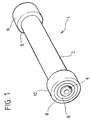
- the reference number 1 designates, as a whole, a container or tank for pressurized fluids, made according to the teachings of the present invention.
- the tank 1 is formed by:
- the main wall 2 is formed by the superimposition of a number of layers of plastic or synthetic material. According to the invention, this is obtained by rolling on itself a number of times at least one sheet or lamina of suitable material, designated by 2A in Figure 2, so as to form a cylindrical chamber 11.
- the said sheet 2A is made via superimposition of a number of layers or films of materials that are different from one another, as will emerge clearly from what follows.
- the sheet 2A may also be entirely made using a single material, whether this be a thermoplastic material or a thermosetting material, selected for example among polyamides, polypropylenes, polyethylenes, polyesters, polyurethanes, polyolefins, polyacrylates, polymethacrylates, and epoxy or elastomeric resins.
- the materials referred to above may conveniently be nanocomposites, meaning thereby the possibility for them to be added with fillers of nanometric dimensions.
- the bushing 3 is full, in as much as it is provided for obstructing the chamber 11 at the rear.
- the bushing 4 is, instead, envisaged for providing a sort of pipe union or pipe fitting and has a through hole for this purpose, the said hole being provided with internal thread so as to enable insertion and fixing thereto of a check valve.
- a similar threaded axial hole from being provided also in the bushing 3.
- the bushings 3 and 4 may be made using any material that is sufficiently rigid for the purpose for which they are designed, such as for example metal or ceramic or synthetic materials.
- the rings 7-10 are preferably made of shape-memory alloy; for this purpose, one of the following alloys may be used: Ni-Ti, Ni-Ti-Cu, Cu-Al-Zn, Cu-Al-Ni.
- SMAs Shape-Memory Alloys
- gaskets 5 and 6 may be made of high-hardness elastomeric material or some other material having similar characteristics.
- the sheet 2A is rolled into a spiral on the bushings 3 and 4, so as to form the main wall 2, of cylindrical shape, which adheres, at its longitudinal ends, to the bushings themselves.
- the seal between the parts may be guaranteed directly by the action of the inner clamping rings 7 and 8, which provide a radial tightening of the wall 2 on the seats 3A and 4A of the bushings 3 and 4, respectively.
- a pressure is applied to the wall 2 so that it will adapt to the external profile of the bushings 3 and 4.
- the cylindrical gaskets 5 and 6 which are provided not so much for guaranteeing a better seal against leakage of the fluid contained in the chamber 11 as for protecting the wall 2 from micro-damage, such damage possibly deriving from the direct contact between the rings 7 and 8 and the wall 2.
- the gaskets 5 and 6 have the purpose of preventing the formation of micro-fractures in the wall 2 from possibly leading to the onset of cracks, which in turn might bring about the subsequent failure of the tank 1.
- the aforesaid degree of protection from micro-damage may possibly be increased by setting further cylindrical gaskets between the wall 2 and the bushings 3 and 4.
- One of such possible further gaskets, set on the bushing 3, is designated in Figure 3 by 5A (a similar gasket may of course be provided also on the bushing 4).
- outer clamping rings 9 and 10 are provided for ensuring uniformity of the radial seal at the longitudinal ends of the tank 1.
- said outer rings 9 and 10 provide in fact for uniform radial loading of the rings 7 and 8 in the direction of the bushings 3 and 4, with the wall 2 and the possible gaskets 5, 6 and 5A set between.
- the sheet 2A that forms the wall 2 may be made up of a plurality of layers of different materials.
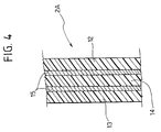
- a possible preferred embodiment in this sense is represented schematically in Figure 4, according to which the sheet 2A is obtained by superimposition of:
- layers of adhesive designated by 15 in Figure 4, which have the job of improving adhesion between the films 12-14; for example, the adhesion between a film 13 made of polyethylene and a film 12 made of polyamide may be improved using a layer 15 of maleic-anhydride based adhesive.
- the various films provided may have different thicknesses from one another, according to the material and the role performed. Any single layer or film provided will preferably have a thickness of between 10 and 100 ⁇ m, so that the superimposition of a number of layers on top of one another will lead to obtaining a sheet 2A of a total thickness of between 50 ⁇ m and 5 mm.
- the layers 12, 13, 14 and 15 of Figure 4 may have thicknesses of up to 30, 30, 20 and 10 ⁇ m, respectively. It is to be noted moreover that the sequence illustrated in Figure 4 may also be repeated for a discrete number of times, until the desired thickness and resistance of the sheet 2A is obtained, the said characteristics being dependent upon the pressure of use of the tank 1.
- the sheet 2A is wound on itself, in the form of a roll, around the bushings 3 and 4, after prior heating of the latter in order to guarantee a perfect adhesion between the parts.
- the main wall 2, having a cylindrical shape, is formed, which adheres at its longitudinal ends to the bushings 3 and 4.
- the gaskets 5A In the case where the gaskets 5A are envisaged, the latter will be fitted on the bushings 3 and 4 before the sheet 2A is rolled a number of times on itself. In the case where the gaskets 5 and 6 are envisaged, these will be fitted on the longitudinal ends of the sheet 2A after the aforesaid winding.
- the pairs of inner clamping rings 7 and 8 are then fitted at the ends of the wall 2 thus formed.
- the rings 7 and 8 are deformed below the martensite-to-austenite transition temperature.
- the said rings, which are made of SMA, are then heated until the aforesaid transition temperature is exceeded, so that they can be fitted on the two longitudinal ends of the wall 2, aligned to the parallel seats 3A and 4A of the bushings themselves.
- the rings 7 and 8 subsequently resume the original shape, tightening in the direction of the bushings 3 and 4, thus guaranteeing the necessary seal.
- outer rings 9 and 10 which are made of SMA, are fitted each on the respective pair of rings 7 and 8, adopting modalities similar to the ones just described, so that the former, as they tend to return to the their original shape, are tightened on the latter, thus guaranteeing the uniformity of the seal in the end areas of the tank 1.
- Containers made according to the invention may find application in various sectors, such as use as tanks for containing gaseous fuels for vehicles, containers for sprays, more or less large-sized cylinders, for example for sport or leisure activities (e.g., cylinders for oxygen, cylinders for camping, etc.).
- the dimensions of the containers according to the invention may hence vary according to the application.
- the number of inner clamping rings 7, 8 made of SMA (and hence of the parallel seats 3A and 4A), as well as of outer rings 9, 10 made of SMA could vary with respect to what is illustrated and described herein by way of example.
- the said means used for radial tightening of the wall 2 on the bushings 3 and 4 may have a shape different from the one illustrated, provided that it is suitable for the proposed purpose, and may be made using a material other than a shape-memory alloy.
- Containers according to the invention may be provided with one or more outer layers of surface coating in order to improve the characteristics of permeability, as well as to provide an adequate mechanical protection and protection against abrasion.
- the materials used for this purpose may be thermosetting plastics (either elastomers or not). It is pointed out that it is also possible to envisage a fire-resistant layer, in order to guarantee flame-proof protection of the container according to the invention.
Landscapes
- Engineering & Computer Science (AREA)
- Mechanical Engineering (AREA)
- Chemical & Material Sciences (AREA)
- Dispersion Chemistry (AREA)
- General Engineering & Computer Science (AREA)
- Filling Or Discharging Of Gas Storage Vessels (AREA)
- Making Paper Articles (AREA)
Abstract
Description
- Figure 1 is a perspective view of a generic container for pressurized fluids, obtained according to the present invention;
- Figure 2 is an exploded view of the container of Figure 1;
- Figure 3 is a cross section of an end area of a container obtained according to the present invention;
- Figure 4 is a partial and schematic cross-sectional view of a portion of a wall of the container of Figure 1, in accordance with a possible embodiment of the invention.
- a
main wall 2, of an on the whole cylindrical shape; - two terminal elements or bushings, designated by 3 and 4, each defining on its own outer surface a pair of parallel seats, designated respectively by 3A and 4A;
- two cylindrical gaskets, which may possibly be used, designated by 5 and 6;
- two pairs of inner clamping rings, designated by 7 and 8; and
- two outer clamping rings, designated by 9 and 10.
- a
first film 12 made of nanocomposite polyamide, which has the job of functioning as barrier for the fluids contained inside the tank 1 and of, at the same time, providing a major structural contribution; - a
second film 13 made of another low-permeability polymeric material, so as to enable use of the tank 1 for containing a given gaseous component. In this perspective, for example, a film made of polyethylene may be employed in the case where the container 1 is to contain alcoholated fuels. It is to be noted therefore that the characteristic of thefilm 13 does not lie so much in the material that makes it up as in the function that it performs; and - a third
elastomeric film 14, for example made of polyurethane, polyester, polyacrylate, polymethacrylate, epoxy resin or polyolefin, which has the job of increasing the mechanical characteristics of the container 1, so guaranteeing a greater resistance to impact. The function of thefilm 14 is likewise that of acting as a bearing between the layers adjacent to it, thus favouring a slight sliding thereof so as to increase the elasticity and resilience, i.e., the impact resistance, of the container.
Claims (17)
- A process for making a container for pressurized fluids (1), which envisages the formation of a wall made of plastic or synthetic material (2), comprising a plurality of adjacent layers and designed to delimit at least in part a chamber (11) for containing the fluid, the said process being characterized in that it envisages the steps of:aligning with respect to one another two terminal elements (3, 4), in particular according to one and the same axis, said terminal elements (3, 4) forming two longitudinal ends of said chamber (11);winding on itself and around said terminal elements (3, 4) at least one lamina (2A), said wall (2) being thus formed by said lamina (2A), the windings of the latter forming said adjacent layers; andtightening radially on said terminal elements (3, 4) the wall (2) formed by the winding of said lamina (2A).
- The process according to Claim 1, in which said wall (2) is tightened radially on each of said terminal elements (3, 4) by means of at least one respective first annular element made of shape-memory alloy (7, 8).
- The process according to Claim 1 or Claim 2, in which said lamina (2A) is in turn formed in a number of layers, in particular made of materials that are different from one another.
- The process according to Claim 1 or Claim 2, in which said lamina (2A) is formed with a single material, in particular a thermoplastic or thermosetting material and selected from the group comprising: polyamides, polypropylenes, polyethylenes, polyesters, polyurethanes, polyolefins, polyacrylates, polymethacrylates, and epoxy or elastomeric resins.
- The process according to Claim 2, in which each of said first annular elements (7, 8) is stressed radially towards the respective terminal element (3, 4) by at least one second element made of shape-memory alloy (9, 10).
- The process according to Claim 1, in which the external profile of each of said terminal elements (3, 4) is previously shaped so as to define at least one depression (3A, 4A) and said wall (2) is liable to undergo deformation to adapt to said profile following said radial tightening.
- The process according to Claim 2, in which between said first annular element (7, 8) and said wall (2) there is inserted at least one gasket (5, 6).
- The process according to Claim 2, in which between said wall (2) and a respective terminal element (3, 4) there is inserted at least one gasket (5A).
- The process according to Claim 3, in which said lamina (2A) is formed by superimposition of at least:between said first, second and third layers there possibly being set an adhesive material (15).one first layer (12) made of nanocomposite polyamide;one second layer (13) made of low-permeability polymeric material; andone third layer (14) made of elastomeric material, in particular set between said first and second layers (12, 13);
- The process according to one or more of the preceding claims, in which said terminal elements (3, 4) are heated before winding of said lamina (2A).
- The process according to one or more of the preceding claims, which envisages the laying of at least one layer of outer surface coating on said wall (2).
- A container for pressurized fluids, which comprises a chamber (11) delimited at least in part by a multilayer wall (2), made using the process according to one or more of Claims 1 to 11.
- A container for pressurized fluids, comprising a chamber (11) delimited at least in part by two longitudinal elements (3, 4), between which there extends a multilayer wall (2), said container being characterized in that said wall (2) is made up of at least one lamina (2A), rolled up on itself and around said longitudinal elements (3, 4) in the form of a roll, and in which there are provided clamping means (7-10), for radially tightening the multilayer wall (2) thus formed on said longitudinal elements (3, 4).
- The container according to Claim 13, characterized in that that said means (7-10) comprise at least a first annular element made of shape-memory alloy (7, 8) which surrounds at least in part a respective longitudinal element (3, 4), with said multilayer wall (2) set between.
- The container according to Claim 14, characterized in that said means (7-10) likewise comprise at least one second annular element made of shape-memory alloy (9, 10), which surrounds a respective first annular element (7, 8).
- A container for pressurized fluids, preferably but not exclusively according to Claim 1, comprising a chamber (11) delimited at least in part by a wall made of multilayer plastic material (2), characterized in that said wall (2) is formed by at least:between two or more of said layers (12, 13, 14) there possibly being set an adhesive material (15).a first layer (12) made of nanocomposite polyamide;a second layer (13) made of polyethylene or similar low-permeability polymeric material; anda third layer (14) made of elastomeric material, such as polyurethane, polyester, polyacrylate, polymethacrylate, epoxy resin or polyolefin, set between said first and second layers (12, 13);
- A process for making a container for pressurized fluids and/or a container for pressurized fluids, substantially as described and illustrated, and for the purposes specified herein.
Applications Claiming Priority (2)
| Application Number | Priority Date | Filing Date | Title |
|---|---|---|---|
| ITTO20011055 ITTO20011055A1 (en) | 2001-11-07 | 2001-11-07 | ,, PROCEDURE FOR THE CREATION OF A CONTAINER FOR PRESSURIZED FLUIDS AND RELATED CONTAINER ,,. |
| ITTO20011055 | 2001-11-07 |
Publications (2)
| Publication Number | Publication Date |
|---|---|
| EP1310728A1 true EP1310728A1 (en) | 2003-05-14 |
| EP1310728B1 EP1310728B1 (en) | 2004-08-04 |
Family
ID=11459289
Family Applications (1)
| Application Number | Title | Priority Date | Filing Date |
|---|---|---|---|
| EP20020023453 Expired - Lifetime EP1310728B1 (en) | 2001-11-07 | 2002-10-21 | A process for making a container for pressurized fluids, and corresponding container |
Country Status (4)
| Country | Link |
|---|---|
| EP (1) | EP1310728B1 (en) |
| DE (1) | DE60200873T2 (en) |
| ES (1) | ES2224012T3 (en) |
| IT (1) | ITTO20011055A1 (en) |
Cited By (1)
| Publication number | Priority date | Publication date | Assignee | Title |
|---|---|---|---|---|
| CN106198371A (en) * | 2016-07-12 | 2016-12-07 | 中国人民解放军第五七九工厂 | A kind of new type rubber oil resistant test device |
Citations (3)
| Publication number | Priority date | Publication date | Assignee | Title |
|---|---|---|---|---|
| US3508677A (en) * | 1968-08-20 | 1970-04-28 | Whittaker Corp | Vessel for storing high-pressure gases |
| US3851786A (en) * | 1971-07-12 | 1974-12-03 | Kaempen Industries | Composite structure |
| US5227208A (en) * | 1991-08-06 | 1993-07-13 | The United States Of America As Represented By The Secretary Of The Army | Integrally wound joint structure |
-
2001
- 2001-11-07 IT ITTO20011055 patent/ITTO20011055A1/en unknown
-
2002
- 2002-10-21 DE DE2002600873 patent/DE60200873T2/en not_active Expired - Fee Related
- 2002-10-21 EP EP20020023453 patent/EP1310728B1/en not_active Expired - Lifetime
- 2002-10-21 ES ES02023453T patent/ES2224012T3/en not_active Expired - Lifetime
Patent Citations (3)
| Publication number | Priority date | Publication date | Assignee | Title |
|---|---|---|---|---|
| US3508677A (en) * | 1968-08-20 | 1970-04-28 | Whittaker Corp | Vessel for storing high-pressure gases |
| US3851786A (en) * | 1971-07-12 | 1974-12-03 | Kaempen Industries | Composite structure |
| US5227208A (en) * | 1991-08-06 | 1993-07-13 | The United States Of America As Represented By The Secretary Of The Army | Integrally wound joint structure |
Cited By (1)
| Publication number | Priority date | Publication date | Assignee | Title |
|---|---|---|---|---|
| CN106198371A (en) * | 2016-07-12 | 2016-12-07 | 中国人民解放军第五七九工厂 | A kind of new type rubber oil resistant test device |
Also Published As
| Publication number | Publication date |
|---|---|
| EP1310728B1 (en) | 2004-08-04 |
| DE60200873D1 (en) | 2004-09-09 |
| ES2224012T3 (en) | 2005-03-01 |
| ITTO20011055A1 (en) | 2003-05-07 |
| DE60200873T2 (en) | 2005-08-04 |
Similar Documents
| Publication | Publication Date | Title |
|---|---|---|
| CA2445586C (en) | Improved composite tubing | |
| EP1314923B1 (en) | Composite high-pressure tube and method of manufacturing the tube | |
| EP1292790B1 (en) | Improvements relating to hose | |
| AU653639B2 (en) | Improved boss for a filament wound pressure vessel | |
| US7568505B2 (en) | Fuel hose | |
| AU2002320710B2 (en) | Composite Pipe Having a PTFE Inner Layer and a Covering Layer of a Fibre-reinforced Plastics Material | |
| CA1155378A (en) | Bearing assembly and method for making same | |
| CN101529144A (en) | Reinforced hose | |
| US6071579A (en) | Laminated air brake tubing | |
| US5885674A (en) | Lining material for pipelines and method for manufacturing the same | |
| EP1310729B1 (en) | A process for making a container for pressurized fluids, and corresponding container | |
| US11994258B2 (en) | Methods of preventing failure of corrugated tube in type IV pressure vessels | |
| EP1310728B1 (en) | A process for making a container for pressurized fluids, and corresponding container | |
| KR100901747B1 (en) | Protective plastic pipes and their manufacture | |
| US6298884B1 (en) | Ebonite hose | |
| EP0027708B1 (en) | Thermoplastic reinforced hose | |
| US20060016499A1 (en) | Flexible, kink resistant, fluid transfer hose construction | |
| CA2756825C (en) | Improved composite tubing | |
| KR100204179B1 (en) | Interance hall of pressure vessel | |
| CA1140845A (en) | Hose | |
| KR20170003618U (en) | Fluoroplastic Color Tube | |
| KR20180030492A (en) | Method for Distinguishing Fluoroplastic Tube for Semiconductor Equipment |
Legal Events
| Date | Code | Title | Description |
|---|---|---|---|
| PUAI | Public reference made under article 153(3) epc to a published international application that has entered the european phase |
Free format text: ORIGINAL CODE: 0009012 |
|
| AK | Designated contracting states |
Designated state(s): AT BE BG CH CY CZ DE DK EE ES FI FR GB GR IE IT LI LU MC NL PT SE SK TR |
|
| AX | Request for extension of the european patent |
Extension state: AL LT LV MK RO SI |
|
| 17P | Request for examination filed |
Effective date: 20030514 |
|
| 17Q | First examination report despatched |
Effective date: 20030716 |
|
| GRAP | Despatch of communication of intention to grant a patent |
Free format text: ORIGINAL CODE: EPIDOSNIGR1 |
|
| AKX | Designation fees paid |
Designated state(s): DE ES FR GB IT SE |
|
| GRAS | Grant fee paid |
Free format text: ORIGINAL CODE: EPIDOSNIGR3 |
|
| GRAA | (expected) grant |
Free format text: ORIGINAL CODE: 0009210 |
|
| AK | Designated contracting states |
Kind code of ref document: B1 Designated state(s): DE ES FR GB IT SE |
|
| REG | Reference to a national code |
Ref country code: GB Ref legal event code: FG4D |
|
| REG | Reference to a national code |
Ref country code: SE Ref legal event code: TRGR |
|
| REG | Reference to a national code |
Ref country code: IE Ref legal event code: FG4D |
|
| REF | Corresponds to: |
Ref document number: 60200873 Country of ref document: DE Date of ref document: 20040909 Kind code of ref document: P |
|
| ET | Fr: translation filed | ||
| REG | Reference to a national code |
Ref country code: ES Ref legal event code: FG2A Ref document number: 2224012 Country of ref document: ES Kind code of ref document: T3 |
|
| PLBE | No opposition filed within time limit |
Free format text: ORIGINAL CODE: 0009261 |
|
| STAA | Information on the status of an ep patent application or granted ep patent |
Free format text: STATUS: NO OPPOSITION FILED WITHIN TIME LIMIT |
|
| 26N | No opposition filed |
Effective date: 20050506 |
|
| PGFP | Annual fee paid to national office [announced via postgrant information from national office to epo] |
Ref country code: SE Payment date: 20061004 Year of fee payment: 5 |
|
| PGFP | Annual fee paid to national office [announced via postgrant information from national office to epo] |
Ref country code: GB Payment date: 20061018 Year of fee payment: 5 |
|
| PGFP | Annual fee paid to national office [announced via postgrant information from national office to epo] |
Ref country code: DE Payment date: 20061019 Year of fee payment: 5 |
|
| PGFP | Annual fee paid to national office [announced via postgrant information from national office to epo] |
Ref country code: IT Payment date: 20061031 Year of fee payment: 5 |
|
| PGFP | Annual fee paid to national office [announced via postgrant information from national office to epo] |
Ref country code: ES Payment date: 20061124 Year of fee payment: 5 |
|
| EUG | Se: european patent has lapsed | ||
| GBPC | Gb: european patent ceased through non-payment of renewal fee |
Effective date: 20071021 |
|
| PG25 | Lapsed in a contracting state [announced via postgrant information from national office to epo] |
Ref country code: DE Free format text: LAPSE BECAUSE OF NON-PAYMENT OF DUE FEES Effective date: 20080501 |
|
| REG | Reference to a national code |
Ref country code: FR Ref legal event code: ST Effective date: 20080630 |
|
| PG25 | Lapsed in a contracting state [announced via postgrant information from national office to epo] |
Ref country code: SE Free format text: LAPSE BECAUSE OF NON-PAYMENT OF DUE FEES Effective date: 20071022 |
|
| PGFP | Annual fee paid to national office [announced via postgrant information from national office to epo] |
Ref country code: FR Payment date: 20061010 Year of fee payment: 5 |
|
| PG25 | Lapsed in a contracting state [announced via postgrant information from national office to epo] |
Ref country code: GB Free format text: LAPSE BECAUSE OF NON-PAYMENT OF DUE FEES Effective date: 20071021 |
|
| REG | Reference to a national code |
Ref country code: ES Ref legal event code: FD2A Effective date: 20071022 |
|
| PG25 | Lapsed in a contracting state [announced via postgrant information from national office to epo] |
Ref country code: ES Free format text: LAPSE BECAUSE OF NON-PAYMENT OF DUE FEES Effective date: 20071022 Ref country code: FR Free format text: LAPSE BECAUSE OF NON-PAYMENT OF DUE FEES Effective date: 20071031 |
|
| PG25 | Lapsed in a contracting state [announced via postgrant information from national office to epo] |
Ref country code: IT Free format text: LAPSE BECAUSE OF NON-PAYMENT OF DUE FEES Effective date: 20071021 |