EP1310726A2 - Fixture for display unit for allowing displayed image to be seen with ease even upon vibrating - Google Patents
Fixture for display unit for allowing displayed image to be seen with ease even upon vibrating Download PDFInfo
- Publication number
- EP1310726A2 EP1310726A2 EP02024477A EP02024477A EP1310726A2 EP 1310726 A2 EP1310726 A2 EP 1310726A2 EP 02024477 A EP02024477 A EP 02024477A EP 02024477 A EP02024477 A EP 02024477A EP 1310726 A2 EP1310726 A2 EP 1310726A2
- Authority
- EP
- European Patent Office
- Prior art keywords
- display unit
- fixing member
- shelf
- connector
- fixture
- Prior art date
- Legal status (The legal status is an assumption and is not a legal conclusion. Google has not performed a legal analysis and makes no representation as to the accuracy of the status listed.)
- Withdrawn
Links
Images


Classifications
-
- G—PHYSICS
- G06—COMPUTING OR CALCULATING; COUNTING
- G06F—ELECTRIC DIGITAL DATA PROCESSING
- G06F1/00—Details not covered by groups G06F3/00 - G06F13/00 and G06F21/00
-
- F—MECHANICAL ENGINEERING; LIGHTING; HEATING; WEAPONS; BLASTING
- F16—ENGINEERING ELEMENTS AND UNITS; GENERAL MEASURES FOR PRODUCING AND MAINTAINING EFFECTIVE FUNCTIONING OF MACHINES OR INSTALLATIONS; THERMAL INSULATION IN GENERAL
- F16M—FRAMES, CASINGS OR BEDS OF ENGINES, MACHINES OR APPARATUS, NOT SPECIFIC TO ENGINES, MACHINES OR APPARATUS PROVIDED FOR ELSEWHERE; STANDS; SUPPORTS
- F16M13/00—Other supports for positioning apparatus or articles; Means for steadying hand-held apparatus or articles
- F16M13/02—Other supports for positioning apparatus or articles; Means for steadying hand-held apparatus or articles for supporting on, or attaching to, an object, e.g. tree, gate, window-frame, cycle
- F16M13/022—Other supports for positioning apparatus or articles; Means for steadying hand-held apparatus or articles for supporting on, or attaching to, an object, e.g. tree, gate, window-frame, cycle repositionable
-
- F—MECHANICAL ENGINEERING; LIGHTING; HEATING; WEAPONS; BLASTING
- F16—ENGINEERING ELEMENTS AND UNITS; GENERAL MEASURES FOR PRODUCING AND MAINTAINING EFFECTIVE FUNCTIONING OF MACHINES OR INSTALLATIONS; THERMAL INSULATION IN GENERAL
- F16M—FRAMES, CASINGS OR BEDS OF ENGINES, MACHINES OR APPARATUS, NOT SPECIFIC TO ENGINES, MACHINES OR APPARATUS PROVIDED FOR ELSEWHERE; STANDS; SUPPORTS
- F16M11/00—Stands or trestles as supports for apparatus or articles placed thereon ; Stands for scientific apparatus such as gravitational force meters
- F16M11/02—Heads
- F16M11/04—Means for attachment of apparatus; Means allowing adjustment of the apparatus relatively to the stand
- F16M11/06—Means for attachment of apparatus; Means allowing adjustment of the apparatus relatively to the stand allowing pivoting
- F16M11/10—Means for attachment of apparatus; Means allowing adjustment of the apparatus relatively to the stand allowing pivoting around a horizontal axis
-
- F—MECHANICAL ENGINEERING; LIGHTING; HEATING; WEAPONS; BLASTING
- F16—ENGINEERING ELEMENTS AND UNITS; GENERAL MEASURES FOR PRODUCING AND MAINTAINING EFFECTIVE FUNCTIONING OF MACHINES OR INSTALLATIONS; THERMAL INSULATION IN GENERAL
- F16M—FRAMES, CASINGS OR BEDS OF ENGINES, MACHINES OR APPARATUS, NOT SPECIFIC TO ENGINES, MACHINES OR APPARATUS PROVIDED FOR ELSEWHERE; STANDS; SUPPORTS
- F16M11/00—Stands or trestles as supports for apparatus or articles placed thereon ; Stands for scientific apparatus such as gravitational force meters
- F16M11/20—Undercarriages with or without wheels
- F16M11/2007—Undercarriages with or without wheels comprising means allowing pivoting adjustment
- F16M11/2021—Undercarriages with or without wheels comprising means allowing pivoting adjustment around a horizontal axis
-
- Y—GENERAL TAGGING OF NEW TECHNOLOGICAL DEVELOPMENTS; GENERAL TAGGING OF CROSS-SECTIONAL TECHNOLOGIES SPANNING OVER SEVERAL SECTIONS OF THE IPC; TECHNICAL SUBJECTS COVERED BY FORMER USPC CROSS-REFERENCE ART COLLECTIONS [XRACs] AND DIGESTS
- Y10—TECHNICAL SUBJECTS COVERED BY FORMER USPC
- Y10S—TECHNICAL SUBJECTS COVERED BY FORMER USPC CROSS-REFERENCE ART COLLECTIONS [XRACs] AND DIGESTS
- Y10S248/00—Supports
- Y10S248/917—Video display screen support
-
- Y—GENERAL TAGGING OF NEW TECHNOLOGICAL DEVELOPMENTS; GENERAL TAGGING OF CROSS-SECTIONAL TECHNOLOGIES SPANNING OVER SEVERAL SECTIONS OF THE IPC; TECHNICAL SUBJECTS COVERED BY FORMER USPC CROSS-REFERENCE ART COLLECTIONS [XRACs] AND DIGESTS
- Y10—TECHNICAL SUBJECTS COVERED BY FORMER USPC
- Y10S—TECHNICAL SUBJECTS COVERED BY FORMER USPC CROSS-REFERENCE ART COLLECTIONS [XRACs] AND DIGESTS
- Y10S248/00—Supports
- Y10S248/917—Video display screen support
- Y10S248/919—Adjustably orientable video screen support
Definitions
- the present invention relates to a fixture for fixing a display unit, in particular a thin display unit such as a liquid crystal display unit, to a shelf.
- Display units such as liquid crystal display units connected to personal computers, for example, are usually placed on a dedicated rack or desk.
- a dedicated rack or desk is called a personal computer rack or personal computer desk, for example.
- a display unit connected to a main unit of a personal computer is placed on a shelf on the rack or desk, and a peripheral device, particularly a printer, of the personal computer is placed on another shelf positioned above and integrally formed with the display unit shelf.
- the personal computer rack or personal computer desk allows the main unit of the personal computer, the display unit, and the peripheral device, particularly a printer to be accommodated in a small space.
- a display unit when the peripheral device operates, e.g., when the printer discharges a printed sheet, it may produce vibrations, which vibrate the personal computer rack or personal computer desk, causing the display unit to resonate.
- the display unit When the display unit resonates, it produces relatively large vibrations, which tend to make it difficult for the user to see the displayed images clearly.
- the present invention is accomplished in view of the aforementioned problem in the prior art, it is therefore an object of the present invention to provide a display unit fixture for preventing a display unit from resonating upon vibrations and allowing the user to see displayed images with ease.
- a fixture for fixing a display unit on a rack having a first shelf and a second shelf disposed upwardly of the first shelf, the display unit being placed on the first shelf and disposed between the first shelf and the second shelf.
- the fixture has a first fixing member fixed to the display unit and a second fixing member removably fixed selectively to a plurality of positions on a surface of the second shelf which faces the first shelf.
- the first fixing member and the second fixing member are connected to each other by a connector for rotation within a plane or planes including an axis interconnecting a joint of the first fixing member to the connector and a joint of the second fixing member to the connector.
- the fixture allows the display unit placed on the first shelf to be also fixed to the second shelf. Even when vibrations occur at the time a printer disposed on the second shelf discharges a printed sheet, the display unit is prevented from resonating by the fixture. Therefore, the user can see-displayed images on the display unit with ease even when vibrations occur.
- the first fixing member and the second fixing member are connected to the connector for rotation in at least a given plane, and the second fixing member is removably fixed to the second shelf at a selected one of the positions. Therefore, after the display screen of the display unit is tilted upwardly or downwardly or to the left or the right, the display unit can be fixed to the second shelf again.
- the second shelf should preferably be made of a material for attracting a magnet, and the second fixing member should preferably have a magnet. While the first fixing member and the second fixing member may be connected to the connector for rotation within any planes including the axis interconnecting the joint of the first fixing member and the joint of the second fixing member, it is enough for the first fixing member and the second fixing member to be connected to the connector for rotation within one and the same plane. The latter arrangement is preferable as it is simpler.
- the connector may have holes defined in opposite ends thereof, and the first fixing member and the second fixing member may have holes defined therein which are held in alignment with the holes defined in the opposite ends of the connector, with a first shaft extending through the hole defined in one of the opposite ends of the connector and the hole defined in the first fixing member, and a second shaft extending through the hole defined in the other of the opposite ends of the connector and the hole defined in the second fixing member.
- the first fixing member should preferably be fixed to an uppermost end of the display unit for effectively suppressing resonation of the display unit.
- the first fixing member may be fixed to the display unit by a double-sided adhesive tape.
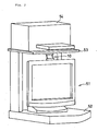
- Display unit 51 comprises a liquid crystal display unit, for example, and has a thin display panel.
- the display panel is supported on a support mounted on shelf 52 for turning its display screen to the left or the right about a vertical axis and also turning the display screen from a vertical plane through a desired angle within a plane perpendicular to the display screen and a horizontal plane.
- Display unit fixture 10 according to the present invention is interposed between the upper end of the display panel and shelf 53.
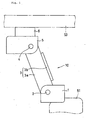
- display unit fixture 10 comprises display unit fixing member (first fixing member) 1 fixed to display unit 51, shelf fixing member 5, and connector 3 interconnecting display unit fixing member 1 and shelf fixing member 5.
- Connector 3 comprises two parallel plates 3a and joint plate 3b interconnecting parallel plates 3a.
- Display unit fixing member 1 is rotatably connected to lower ends of parallel plates 3a by shaft 2
- shelf fixing member 5 is rotatably connected to upper ends of parallel plates 3a by shaft 4.
- Shaft 2 extends through holes defined in the lower ends of parallel plates 3a and holes defined in display unit fixing member 1 which are held in alignment with the holes defined in the lower ends of parallel plates 3a.
- Shaft 4 extends through holes defined in the upper ends of parallel plates 3a and holes defined in shelf fixing member 5 which are held in alignment with the holes defined in the upper ends of parallel plates 3a.
- Display unit fixing member 1 and shelf fixing member 5 are thus coupled to each other for rotation with respect to connector 3 within a plane perpendicular to the display screen of display unit 51 and a horizontal plane.
- Display unit fixing member 1 may be fixed to display unit 51 by a double-sided adhesive tape, for example. However, display unit fixing member 1 may be fixed to display unit 51 by any of various fixing arrangements. Shelf 53 which is positioned above shelf 52 on which display unit 51 is placed is made of a material capable of attracting a magnet under magnetic forces. Magnet 6 is fixed to shelf fixing member 5. Shelf fixing member 5 and magnet 6 jointly make up a second fixing member which can removably be fixed to shelf 53 at any desired position on its lower surface.
- Display unit fixture 10 thus constructed is installed between display unit 51 and shelf 53 disposed thereabove, with display unit fixing member 1 fixed to display unit 51 and magnet 6 fixed to the lower surface of shelf 53 at any desired variable position thereon. Even when vibrations occur when printer 54 discharges a printed sheet and such vibrations are transmitted to shelf 52, display unit fixture 10 prevents display unit 51 from resonating. Therefore, even when vibrations are produced, the user can see displayed images on display unit 51 with ease.
- Display unit fixture 10 allows the display panel of display unit 51 to be turned to the left or the right about a vertical axis and also allows the display panel to be tilted from a vertical plane. Even after the display panel is thus turned or tilted, display unit fixture 10 keeps display unit 51 fixed in position. Operation of display unit fixture 10 for moving the display panel of display unit 51 will be described below.
- a mode of operation of display unit fixture 10 for tilting the display panel within a plane perpendicular to the display screen and a horizontal plane, i.e., for tilting the display screen upwardly or downwardly will be described below with reference to Figs. 3 through 5.
- Figs. 3 through 5 show the display unit 51 or the display unit fixture 10 when the display screen of display unit 51 which is tilted upwardly from the position shown in Fig. 2.
- display unit fixing member 1 fixed to the upper end of display unit 51 is tilted with respect to the surface of shelf 52 in unison with the display screen and is moved in position.
- connector 3 is turned about shafts 2 and 4 in the plane perpendicular to the display screen and the horizontal plane and is moved.
- shelf fixing member 5 and magnet 6 fixed thereto move along the lower surface of shelf 53, the surface of magnet 6 being attracted to and kept along the lower surface of shelf 53.
- a mode of operation of display unit fixture 10 for turning the display panel in a horizontal plane, i.e., for orienting the display panel to the left or the right, will be described below with reference to Figs. 6 through 8.
- display unit fixture 10 When the display panel is turned to the right, display unit fixture 10 operates in the same manner as described above. Display unit 51 remains fixed to shelf 53 by display unit fixture 10 after the display panel is oriented to the right as shown in Fig. 8. After the display panel is oriented to the right, display unit fixture 10 therefore prevents display unit 51 from resonating.
- connector 3 comprises members of fixed length. However, connector 3 may be arranged to change its length as the distance between the portion of display unit 51 which is fixed to display unit fixture 10 and the lower surface of shelf 53 is changed when the display screen of display unit 51 changes its orientation.
- the display unit to which display unit fixture 10 is attached is not limited to a liquid crystal display unit, but may be any of various other display units, e.g., a CRT display unit.
- the second fixing member is fixed to the lower surface of shelf 53 by magnet 6, and hence can have its fixed position changed.
- the second fixing member may be removably fixed to the lower surface of shelf 53 at least at a selected one of plural positions thereon. With such a selective positioning mechanism, if the fixed position of the second fixing member, including its orientation, needs to be changed, then the second fixing member is removed from the present fixed position and fixed to a new fixed position.
- first fixing member and the second fixing member are coupled to the respective opposite ends of the connector for rotation within one and the same plane.
- first fixing member and the second fixing member may be respectively rotatable within any planes including an axis interconnecting the joint of the first fixing member to the connector and the joint of the second fixing member to the connector.
Landscapes
- Engineering & Computer Science (AREA)
- General Engineering & Computer Science (AREA)
- Mechanical Engineering (AREA)
- Theoretical Computer Science (AREA)
- Physics & Mathematics (AREA)
- General Physics & Mathematics (AREA)
- Devices For Indicating Variable Information By Combining Individual Elements (AREA)
Abstract
Description
Claims (6)
- A fixture for fixing a display unit on a rack having a first shelf and a second shelf disposed upwardly of said first shelf, said display unit being placed on the first shelf and disposed between the first shelf and the second shelf, comprising:a first fixing member fixed to said display unit;a second fixing member removably fixed selectively to a plurality of positions on a surface of said second shelf which faces said first shelf; anda connector interconnecting said first fixing member and said second fixing member;said first fixing member and said second fixing member being connected to said connector for rotation within a plane or planes including an axis interconnecting a joint of said first fixing member to said connector and a joint of said second fixing member to said connector.
- A fixture according to claim 1, wherein said second shelf is made of a material for attracting a magnet, and said second fixing member has a magnet.
- A fixture according to claim 1 or 2, wherein
said first fixing member and said second fixing member are connected to said connector for rotation within one and the same plane. - A fixture according to claim 3, wherein said connector has holes defined in opposite ends thereof, and said first fixing member and said second fixing member have holes defined therein which are held in alignment with said holes defined in the opposite ends of said connector, further comprising a first shaft extending through the hole defined in one of the opposite ends of said connector and the hole defined in said first fixing member, and a second shaft extending through the hole defined in the other of the opposite ends of said connector and the hole defined in said second fixing member.
- A fixture according to claim 1, 2, 3 or 4, wherein
said first fixing member is fixed to an uppermost end of said display unit. - A fixture according to claim 1, 2, 3, 4 or 5, wherein
said first fixing member is fixed to said display unit by a double-sided adhesive tape.
Applications Claiming Priority (2)
| Application Number | Priority Date | Filing Date | Title |
|---|---|---|---|
| JP2001346604 | 2001-11-12 | ||
| JP2001346604A JP3687589B2 (en) | 2001-11-12 | 2001-11-12 | Fixture for display device |
Publications (2)
| Publication Number | Publication Date |
|---|---|
| EP1310726A2 true EP1310726A2 (en) | 2003-05-14 |
| EP1310726A3 EP1310726A3 (en) | 2004-03-17 |
Family
ID=19159754
Family Applications (1)
| Application Number | Title | Priority Date | Filing Date |
|---|---|---|---|
| EP02024477A Withdrawn EP1310726A3 (en) | 2001-11-12 | 2002-10-30 | Fixture for display unit for allowing displayed image to be seen with ease even upon vibrating |
Country Status (6)
| Country | Link |
|---|---|
| US (2) | US7341235B2 (en) |
| EP (1) | EP1310726A3 (en) |
| JP (1) | JP3687589B2 (en) |
| KR (1) | KR100483419B1 (en) |
| CN (1) | CN1196883C (en) |
| TW (1) | TW558616B (en) |
Cited By (4)
| Publication number | Priority date | Publication date | Assignee | Title |
|---|---|---|---|---|
| US7661645B2 (en) | 2001-11-12 | 2010-02-16 | Nec Corporation | Fixture for display unit for allowing displayed image to be seen with ease even upon vibrating |
| EP1973447A4 (en) * | 2006-01-06 | 2012-05-23 | Sung Jin Kim | Shelf for display apparatus |
| CN102962699A (en) * | 2012-10-26 | 2013-03-13 | 南通德玛瑞机械制造有限公司 | Universal support frame |
| ITRM20120087A1 (en) * | 2012-03-08 | 2013-09-09 | Silvia Verna | "ANCHORABLE SUPPORT STRUCTURE FOR THE CEILING, FOR SUPPORT TABLES AND / OR FOR FIXING ELEMENTS" |
Families Citing this family (7)
| Publication number | Priority date | Publication date | Assignee | Title |
|---|---|---|---|---|
| WO2007052410A1 (en) * | 2005-11-04 | 2007-05-10 | Nec Personal Products, Ltd. | Electronic device and rack member |
| JP2007334258A (en) * | 2006-06-19 | 2007-12-27 | Sharp Corp | Thin display device |
| US8174823B2 (en) * | 2009-06-15 | 2012-05-08 | Twelve South LLC | Computer monitor with a shelf |
| KR101126558B1 (en) | 2011-07-08 | 2012-03-13 | 이정근 | Fence type led advertising apparatus |
| US9420887B2 (en) * | 2014-02-25 | 2016-08-23 | Marc Reviel | Detachable shelf with swivel point for monitors |
| US10066783B2 (en) * | 2015-01-02 | 2018-09-04 | Suncraft Solutions, Inc. | Support assembly for vertically disposed objects, such as televisions and video monitors |
| USD792419S1 (en) | 2015-01-02 | 2017-07-18 | Suncraft Solutions, Inc. | Support assembly for vertically disposed objects |
Family Cites Families (44)
| Publication number | Priority date | Publication date | Assignee | Title |
|---|---|---|---|---|
| US3726498A (en) * | 1971-11-23 | 1973-04-10 | All American Ind | Pendant supporting and retaining device for arresting aircraft |
| US3774873A (en) * | 1971-11-24 | 1973-11-27 | Jacobsen As J | Equipoised arm assembly |
| US4470106A (en) * | 1983-04-06 | 1984-09-04 | Norton Larry G | Shop light |
| US4577788A (en) * | 1984-09-24 | 1986-03-25 | Richardson Jennings R | Portable multipurpose desk container |
| JPS63175224A (en) | 1987-01-14 | 1988-07-19 | Matsushita Electric Ind Co Ltd | magnetic recording medium |
| GB2206279B (en) * | 1987-06-26 | 1991-06-05 | Vincent Anthony Yates | Stand for a computer keyboard and a separately framed display unit |
| US4836478A (en) * | 1987-10-15 | 1989-06-06 | Ergotron, Inc. | Suspension system for personal computers and monitors |
| JP3057684B2 (en) | 1989-05-09 | 2000-07-04 | 淀川化成株式会社 | Glass substrate cassette |
| JPH0754036Y2 (en) | 1989-06-28 | 1995-12-13 | 株式会社本田ロック | Vehicle outside mirror |
| JPH0357684U (en) | 1989-10-12 | 1991-06-04 | ||
| US4964606A (en) * | 1989-10-26 | 1990-10-23 | Ncr Corporation | Overhead mount for a CRT |
| US4993676A (en) * | 1990-01-16 | 1991-02-19 | Fitts William E | Apparatus for supporting a television set from a ceiling |
| JP2933092B2 (en) | 1990-10-15 | 1999-08-09 | 富士通株式会社 | Document reading device |
| US5143338A (en) * | 1991-07-30 | 1992-09-01 | Woodwork Restoration, Inc. | Holding device |
| US5180136A (en) * | 1991-08-19 | 1993-01-19 | Weber-Knapp Company | Counterbalance mechanism |
| US5154390A (en) * | 1991-08-30 | 1992-10-13 | Bain Charles E | Articulated stand for supporting object |
| JPH0580306A (en) | 1991-09-19 | 1993-04-02 | Hitachi Ltd | Liquid crystal display device |
| US5381991A (en) * | 1992-02-21 | 1995-01-17 | Sign-Up, Inc. | Suspended display holder |
| US5400993A (en) * | 1993-08-17 | 1995-03-28 | Hamilton; Clifton | Adjustable overhead suspension apparatus for TV and VCR |
| CN2193279Y (en) | 1994-06-02 | 1995-03-29 | 怡利电子工业股份有限公司 | A lever type hanging rack |
| DE9409337U1 (en) * | 1994-06-09 | 1994-07-28 | E. Lead Electronic Co. Ltd., Changhua | Holding device for utensils or equipment, especially in motor vehicles |
| JPH0899450A (en) | 1994-09-30 | 1996-04-16 | Bridgestone Corp | Apparatus for preventing rolling of printer |
| US5584253A (en) * | 1995-06-08 | 1996-12-17 | Stranford; James A. | Television supported shelf |
| US5738320A (en) * | 1996-05-13 | 1998-04-14 | Fellowes Manufacturing Company | Support shelf for computer monitors |
| US5842672A (en) * | 1996-06-07 | 1998-12-01 | Ergotron, Inc. | Mounting system for flat panel display, keyboard and stand |
| US5988571A (en) * | 1997-09-22 | 1999-11-23 | Ward; Glenn F. | TV/VCR mount |
| US5996954A (en) * | 1997-10-14 | 1999-12-07 | Rosen Products Llc | Stowable support apparatus |
| JPH11282421A (en) | 1998-03-26 | 1999-10-15 | Advanced Display Inc | Liquid crystal display device |
| JPH11259050A (en) | 1998-03-13 | 1999-09-24 | Advanced Display Inc | Driving method and driving device of liquid crystal display device |
| JPH11327783A (en) | 1998-05-21 | 1999-11-30 | Canon Inc | Information equipment |
| US6061104A (en) * | 1998-07-22 | 2000-05-09 | Silicon Graphics, Inc. | Flat panel display and stand with vertical adjustment and tilt adjustment |
| US6247205B1 (en) * | 1999-02-17 | 2001-06-19 | Jevan A. Damadian | Apparatus to enable hands-free use of a long-distance magnifying device |
| JP3825598B2 (en) * | 1999-11-25 | 2006-09-27 | パイオニア株式会社 | Display device |
| US7077373B1 (en) * | 2000-01-05 | 2006-07-18 | Da-Lite Screen Co., Inc. | Mount for TV monitor |
| US6466278B1 (en) * | 2000-01-06 | 2002-10-15 | Icebox, Llc | Appliances |
| US6398178B1 (en) * | 2000-04-26 | 2002-06-04 | Anthony Azola | Organizational device |
| TW487277U (en) * | 2000-12-01 | 2002-05-11 | Acer Inc | Flat-panel display device and mounting device thereof |
| USD455949S1 (en) * | 2000-12-27 | 2002-04-23 | Associated Industries China, Inc. | Arm for supporting LCD displayer |
| US6478275B1 (en) * | 2001-08-31 | 2002-11-12 | Min Hwa Huang | Support device for monitor, displayer or other object |
| US6595104B2 (en) * | 2001-09-27 | 2003-07-22 | Tri Motion Industries Of Florida | Pilot control for a hoist and balancing apparatus |
| JP3687589B2 (en) | 2001-11-12 | 2005-08-24 | 日本電気株式会社 | Fixture for display device |
| US7019786B2 (en) * | 2002-01-15 | 2006-03-28 | Hannstar Display Corp. | TV wall for liquid crystal displays |
| JP2003330379A (en) * | 2002-03-04 | 2003-11-19 | Canon Inc | Display panel support device |
| US6595482B1 (en) * | 2002-07-29 | 2003-07-22 | Franz O. Armbruster | Magnetic suspension bracket construction |
-
2001
- 2001-11-12 JP JP2001346604A patent/JP3687589B2/en not_active Expired - Fee Related
-
2002
- 2002-10-23 TW TW091124445A patent/TW558616B/en not_active IP Right Cessation
- 2002-10-30 EP EP02024477A patent/EP1310726A3/en not_active Withdrawn
- 2002-11-08 CN CNB021504091A patent/CN1196883C/en not_active Expired - Fee Related
- 2002-11-08 US US10/290,238 patent/US7341235B2/en not_active Expired - Fee Related
- 2002-11-11 KR KR10-2002-0069495A patent/KR100483419B1/en not_active Expired - Fee Related
-
2007
- 2007-06-15 US US11/812,190 patent/US7661645B2/en not_active Expired - Fee Related
Cited By (4)
| Publication number | Priority date | Publication date | Assignee | Title |
|---|---|---|---|---|
| US7661645B2 (en) | 2001-11-12 | 2010-02-16 | Nec Corporation | Fixture for display unit for allowing displayed image to be seen with ease even upon vibrating |
| EP1973447A4 (en) * | 2006-01-06 | 2012-05-23 | Sung Jin Kim | Shelf for display apparatus |
| ITRM20120087A1 (en) * | 2012-03-08 | 2013-09-09 | Silvia Verna | "ANCHORABLE SUPPORT STRUCTURE FOR THE CEILING, FOR SUPPORT TABLES AND / OR FOR FIXING ELEMENTS" |
| CN102962699A (en) * | 2012-10-26 | 2013-03-13 | 南通德玛瑞机械制造有限公司 | Universal support frame |
Also Published As
| Publication number | Publication date |
|---|---|
| US7341235B2 (en) | 2008-03-11 |
| KR100483419B1 (en) | 2005-04-18 |
| TW558616B (en) | 2003-10-21 |
| KR20030040079A (en) | 2003-05-22 |
| US7661645B2 (en) | 2010-02-16 |
| EP1310726A3 (en) | 2004-03-17 |
| US20080035829A1 (en) | 2008-02-14 |
| JP2003150069A (en) | 2003-05-21 |
| CN1196883C (en) | 2005-04-13 |
| JP3687589B2 (en) | 2005-08-24 |
| US20030089835A1 (en) | 2003-05-15 |
| CN1419070A (en) | 2003-05-21 |
Similar Documents
| Publication | Publication Date | Title |
|---|---|---|
| US7661645B2 (en) | Fixture for display unit for allowing displayed image to be seen with ease even upon vibrating | |
| JP3682467B2 (en) | Multi display device | |
| KR100553677B1 (en) | Portable computer having a structure for supporting the cover | |
| JP3543729B2 (en) | Display panel housing of information processing device | |
| US9824547B2 (en) | Cash register system with pivotable arms | |
| CN102622047A (en) | Portable electronic device | |
| US7268999B2 (en) | Display apparatus | |
| EP1772661A2 (en) | Stand for image display device | |
| US8009414B2 (en) | Electronic equipment and shelf member | |
| JP2000187446A (en) | Supporting device for flat display | |
| JP2006064786A (en) | Liquid crystal display device | |
| JP7123784B2 (en) | Display device with touch panel | |
| JP4561866B2 (en) | Display screen support mechanism and television apparatus | |
| JP3125333U (en) | Stand device for portable game machine | |
| JP6760618B1 (en) | POS terminal device | |
| JP7500518B2 (en) | Information processing device, display device and housing | |
| JP2002229676A (en) | Information processing system and display device | |
| JP6624315B1 (en) | Electronics | |
| JP3069891U (en) | Information processing device, thin display device of information processing device, and dedicated desk | |
| JP2008089928A (en) | Projection device | |
| JP2001189901A (en) | Projection display device | |
| JPH1195318A (en) | Multi-screen display device | |
| KR20050123452A (en) | Display apparatus | |
| JPH01206390A (en) | Display device | |
| JPH11194712A (en) | Display device |
Legal Events
| Date | Code | Title | Description |
|---|---|---|---|
| PUAI | Public reference made under article 153(3) epc to a published international application that has entered the european phase |
Free format text: ORIGINAL CODE: 0009012 |
|
| AK | Designated contracting states |
Designated state(s): AT BE BG CH CY CZ DE DK EE ES FI FR GB GR IE IT LI LU MC NL PT SE SK TR |
|
| AX | Request for extension of the european patent |
Extension state: AL LT LV MK RO SI |
|
| PUAL | Search report despatched |
Free format text: ORIGINAL CODE: 0009013 |
|
| AK | Designated contracting states |
Kind code of ref document: A3 Designated state(s): AT BE BG CH CY CZ DE DK EE ES FI FR GB GR IE IT LI LU MC NL PT SE SK TR |
|
| AX | Request for extension of the european patent |
Extension state: AL LT LV MK RO SI |
|
| 17P | Request for examination filed |
Effective date: 20040203 |
|
| 17Q | First examination report despatched |
Effective date: 20040721 |
|
| AKX | Designation fees paid |
Designated state(s): DE FR GB |
|
| STAA | Information on the status of an ep patent application or granted ep patent |
Free format text: STATUS: THE APPLICATION IS DEEMED TO BE WITHDRAWN |
|
| 18D | Application deemed to be withdrawn |
Effective date: 20130403 |