EP1310676A1 - Pumping device with Moineau pump - Google Patents
Pumping device with Moineau pump Download PDFInfo
- Publication number
- EP1310676A1 EP1310676A1 EP02292711A EP02292711A EP1310676A1 EP 1310676 A1 EP1310676 A1 EP 1310676A1 EP 02292711 A EP02292711 A EP 02292711A EP 02292711 A EP02292711 A EP 02292711A EP 1310676 A1 EP1310676 A1 EP 1310676A1
- Authority
- EP
- European Patent Office
- Prior art keywords
- rotor
- connecting rod
- driving shaft
- cavity
- pumping device
- Prior art date
- Legal status (The legal status is an assumption and is not a legal conclusion. Google has not performed a legal analysis and makes no representation as to the accuracy of the status listed.)
- Granted
Links
Images


Classifications
-
- F—MECHANICAL ENGINEERING; LIGHTING; HEATING; WEAPONS; BLASTING
- F04—POSITIVE - DISPLACEMENT MACHINES FOR LIQUIDS; PUMPS FOR LIQUIDS OR ELASTIC FLUIDS
- F04C—ROTARY-PISTON, OR OSCILLATING-PISTON, POSITIVE-DISPLACEMENT MACHINES FOR LIQUIDS; ROTARY-PISTON, OR OSCILLATING-PISTON, POSITIVE-DISPLACEMENT PUMPS
- F04C2/00—Rotary-piston machines or pumps
- F04C2/08—Rotary-piston machines or pumps of intermeshing-engagement type, i.e. with engagement of co-operating members similar to that of toothed gearing
- F04C2/10—Rotary-piston machines or pumps of intermeshing-engagement type, i.e. with engagement of co-operating members similar to that of toothed gearing of internal-axis type with the outer member having more teeth or tooth-equivalents, e.g. rollers, than the inner member
- F04C2/107—Rotary-piston machines or pumps of intermeshing-engagement type, i.e. with engagement of co-operating members similar to that of toothed gearing of internal-axis type with the outer member having more teeth or tooth-equivalents, e.g. rollers, than the inner member with helical teeth
- F04C2/1071—Rotary-piston machines or pumps of intermeshing-engagement type, i.e. with engagement of co-operating members similar to that of toothed gearing of internal-axis type with the outer member having more teeth or tooth-equivalents, e.g. rollers, than the inner member with helical teeth the inner and outer member having a different number of threads and one of the two being made of elastic materials, e.g. Moineau type
-
- F—MECHANICAL ENGINEERING; LIGHTING; HEATING; WEAPONS; BLASTING
- F04—POSITIVE - DISPLACEMENT MACHINES FOR LIQUIDS; PUMPS FOR LIQUIDS OR ELASTIC FLUIDS
- F04C—ROTARY-PISTON, OR OSCILLATING-PISTON, POSITIVE-DISPLACEMENT MACHINES FOR LIQUIDS; ROTARY-PISTON, OR OSCILLATING-PISTON, POSITIVE-DISPLACEMENT PUMPS
- F04C15/00—Component parts, details or accessories of machines, pumps or pumping installations, not provided for in groups F04C2/00 - F04C14/00
- F04C15/0057—Driving elements, brakes, couplings, transmission specially adapted for machines or pumps
- F04C15/0061—Means for transmitting movement from the prime mover to driven parts of the pump, e.g. clutches, couplings, transmissions
- F04C15/0065—Means for transmitting movement from the prime mover to driven parts of the pump, e.g. clutches, couplings, transmissions for eccentric movement
Definitions
- the ball 15 forms a offset rotary joint compatible with the double rotation movement inherent in the pump Sparrow (rotational movement of the rotor around its own axis and rotational movement of the rotor axis in reverse around the stator axis) and suitable for authorize a significant mutual inclination of the connecting rod 5 relative to the end of the rotor 2 or of the driving shaft 3, respectively, when rotating the driving shaft driving the rotor.
- the connecting rod 5 can be constituted by the assembly of three parts, namely a rigid bar, in particular metallic (for example steel) forming the aforementioned connecting rod 13 - it may be in particular of a round section of steel in diameter suitable and cut to the desired length - and two metallic spheres (especially steel) which are attached and secured to the front ends of the rigid bar.
- a rigid bar in particular metallic (for example steel) forming the aforementioned connecting rod 13 - it may be in particular of a round section of steel in diameter suitable and cut to the desired length - and two metallic spheres (especially steel) which are attached and secured to the front ends of the rigid bar.
- metallic spheres especially steel
Abstract
Description
La présente invention concerne des perfectionnements apportés aux dispositifs de pompage comprenant une pompe à cavités progressives ou pompes Moineau avec un rotor hélicoïdal intérieur à une cavité hélicoïdale d'un stator, des moyens moteurs avec un arbre menant sensiblement coaxial à la cavité du stator, et une bielle d'entraínement qui est interposée entre l'arbre menant des moyens moteurs et une extrémité du rotor auxquels elle est accouplée par des moyens d'accouplement respectifs agencés pour que ladite bielle puisse accompagner le double mouvement de rotation du rotor (rotation du rotor autour de son propre axe et rotation de l'axe du rotor autour de l'axe de la cavité du stator).The present invention relates to improvements supplied to pumping devices comprising a progressive cavity pump or sparrow pumps with a helical rotor inside a helical cavity of a stator, motor means with a driving shaft substantially coaxial with the stator cavity, and a connecting rod which is interposed between the shaft leading to motor means and one end of the rotor to which it is coupled by respective coupling means arranged so that said rod can accompany double rotor rotation movement (rotor rotation around of its own axis and rotation of the rotor axis around the axis of the stator cavity).
Compte tenu du double mouvement de rotation du rotor, d'une part, et de l'absence de coaxialité du rotor et de l'arbre menant des moyens moteurs, d'autre part, la bielle occupe une position inclinée et, au cours de son mouvement de rotation, elle se déplace selon une enveloppe conique. Il en résulte l'obligation d'accoupler la bielle à l'arbre menant des moyens moteurs et à l'extrémité du rotor de façon qu'elle puisse occuper une position inclinée par rapport aux axes respectifs, parallèles mais non coaxiaux, de ceux-ci en même temps qu'elle assume sa fonction de transmission du couple.Given the double rotational movement of the rotor, on the one hand, and the absence of coaxiality of the rotor and of the shaft driving the driving means, on the other hand, the connecting rod occupies an inclined position and, during its rotational movement, it moves in an envelope conical. This results in the obligation to couple the connecting rod to the shaft leading to the driving means and to the end of the rotor so that it can occupy a position inclined with respect to the respective axes, parallel but non-coaxial, of these at the same time as it assumes its torque transmission function.
Pour satisfaire cette obligation, il est courant de réaliser la bielle sous forme d'un barreau métallique et de prévoir des accouplements appropriés entre ses deux extrémités et respectivement l'arbre menant des moyens moteurs et l'extrémité du rotor. De nombreux types d'accouplement sont connus dans ce contexte. Un accouplement cardan classique ne permettant pas une inclinaison suffisante de la bielle (ou exigeant alors une bielle de longueur importante), on connaít notamment diverses réalisations d'accouplement dérivées de l'accouplement cardan, mais autorisant des inclinaisons plus importantes, et donc permettant de réaliser des bielles plus courtes.To meet this obligation, it is common to make the rod in the form of a metal bar and to provide appropriate couplings between its two ends and respectively the shaft leading means motors and the rotor end. Many types are known in this context. A classic cardan coupling not allowing a sufficient inclination of the connecting rod (or requiring a connecting rod of significant length), we know in particular various mating designs derived from the cardan coupling, but allowing inclinations more important, and therefore allowing to realize shorter connecting rods.
Toutefois ces accouplements connus présentent l'inconvénient d'être constitués d'un nombre élevé de pièces, ce qui en accroít le coût de fabrication et le coût d'entretien.However, these known couplings have the disadvantage of being made up of a large number of parts, which increases the manufacturing cost and maintenance cost.
En outre, certaines de ces pièces, mutuellement rotatives, sont assemblées par l'intermédiaire d'axes de rotation ou de pivotement. Or, la bielle doit être en mesure de supporter des efforts de compression axiaux générés par les réactions du rotor de pompe en cours de fonctionnement : les axes précités doivent notamment être en mesure d'encaisser ces efforts sans rupture, ce qui conduit à les surdimensionner.In addition, some of these pieces, mutually rotary, are assembled by means of axes rotation or pivoting. However, the connecting rod must be in able to withstand axial compression forces generated by the reactions of the pump rotor during operation: the aforementioned axes must in particular be able to withstand these efforts without breaking, which leads to oversize them.
L'invention a essentiellement pour but de proposer un agencement perfectionné d'accouplement propre à autoriser une inclinaison importante de la bielle - et donc de conduire à un raccourcissement de cette bielle - tout en ne comportant qu'un nombre très restreint de pièces constitutives qui ne font appel à aucun axe d'articulation, et qui par conséquent est propre à supporter sans endommagement des efforts élevés de réaction axiaux, les pièces constitutives étant simples et peu coûteuses.The object of the invention is essentially to propose an improved coupling arrangement specific to allow a significant inclination of the connecting rod - and therefore lead to a shortening of this connecting rod - while having only a very limited number of constituent parts which do not use any axis of articulation, and which consequently is specific to withstand without damage the high efforts of axial reaction, the constituent parts being simple and inexpensive.
A ces fins, un dispositif de pompage tel que mentionné au préambule se caractérise, étant agencé conformément à l'invention, en ce que chacun desdits moyens d'accouplement comprend
- une tête sphérique solidaire de la bielle, respectivement de l'extrémité du rotor ou de l'arbre menant,
- une cavité cylindrique de révolution de même diamètre que la susdite tête sphérique pour recevoir celle-ci et solidaire coaxialement de l'extrémité du rotor ou de l'arbre menant, respectivement de la bielle, et
- une bille abritée, pour partie, dans une cuvette en calotte sphérique de forme complémentaire pratiquée dans la tête sphérique qui est disposée de manière que son axe soit sensiblement perpendiculaire à l'axe de la bielle, respectivement de l'extrémité du rotor ou de l'arbre menant, et, pour partie, dans un évidement latéral de dimensions complémentaires pratiqué dans la cavité cylindrique de révolution,
- a spherical head secured to the connecting rod, respectively to the end of the rotor or of the driving shaft,
- a cylindrical cavity of revolution of the same diameter as the aforementioned spherical head to receive the latter and coaxially secured to the end of the rotor or of the driving shaft, respectively of the connecting rod, and
- a ball sheltered, in part, in a bowl in a spherical cap of complementary shape formed in the spherical head which is arranged so that its axis is substantially perpendicular to the axis of the connecting rod, respectively from the end of the rotor or of the 'driving shaft, and, in part, in a lateral recess of complementary dimensions made in the cylindrical cavity of revolution,
Dans un mode de réalisation préféré, la tête sphérique est solidaire de la bielle et la cavité cylindrique de révolution est prévue sur l'extrémité du rotor, respectivement sur l'arbre menant. Dans un exemple de mise en oeuvre simple, on profite du fait que de telles têtes sphériques sont couramment disponibles dans le commerce : on peut alors faire en sorte que la bielle comprenne un barreau rigide formant une tige de bielle aux extrémités respectives de laquelle sont solidarisées (notamment par soudure) deux têtes sphériques. In a preferred embodiment, the head spherical is integral with the connecting rod and the cavity cylindrical of revolution is provided on the end of the rotor, respectively on the driving shaft. In an example simple implementation, we take advantage of the fact that such spherical heads are commonly available in the trade: we can then arrange for the connecting rod includes a rigid bar forming a connecting rod rod respective ends of which are secured (in particular by welding) two spherical heads.
Dans un mode de réalisation de conception simple, la cavité cylindrique de révolution est définie dans une douille creuse solidaire de l'extrémité du rotor ou de l'arbre menant et le susdit évidement latéral prévu dans ladite cavité est défini par un trou traversant radialement la paroi latérale de ladite douille et par une bague rapportée sur la paroi externe de ladite douille pour obturer extérieurement le susdit trou. Notamment, la bague externe est fixée à la douille par au moins une vis radiale.In a simple design embodiment, the cylindrical cavity of revolution is defined in a hollow socket integral with the end of the rotor or the driving shaft and the aforesaid lateral recess provided in said cavity is defined by a through hole radially the side wall of said socket and by a ring attached to the outer wall of said socket to seal the above-mentioned hole externally. In particular, the outer ring is fixed to the socket by at least one screw radial.
Grâce aux dispositions qui viennent d'être énoncées, on constitue un accouplement dans lequel la bille assume la double fonction d'articulation rotative et d'organe de transmission des efforts axiaux : ainsi il n'existe plus d'axe de pivotement. Au surplus, le nombre des pièces composantes est réduit et leur assemblage est simple sans qu'il soit nécessaire d'exécuter des usinages complexes. Enfin, conformément au but poursuivi, la bielle est susceptible d'inclinaisons notables, de sorte qu'il est possible d'envisager un raccourcissement sensible de la bielle entraínant une plus grande compacité du dispositif de pompage.Thanks to the provisions which have just been stated, we constitute a coupling in which the ball assumes the double function of rotary articulation and organ for transmitting axial forces: thus it there is no longer a pivot axis. In addition, the number component parts is reduced and their assembly is simple without the need to perform machining complex. Finally, in accordance with the aim pursued, the connecting rod is susceptible to notable inclinations, so it is possible to consider a significant shortening of the rod resulting in greater compactness of the pumping device.
On peut encore obtenir des inclinaisons plus prononcées de la bielle en prévoyant que la partie annulaire de la paroi interne de la douille située entre ledit évidement latéral et l'extrémité de la douille soit de conformation tronconique.We can still get more inclinations pronounced from the connecting rod providing that the part annular of the inner wall of the socket located between said lateral recess and the end of the socket either of frustoconical conformation.
L'invention sera mieux comprise à la lecture de la description détaillée qui suit de certains modes de réalisation préférés donnés uniquement à titre d'exemples nullement limitatifs. Dans cette description, on se réfère aux dessins annexés sur lesquels :
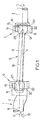
- la figure 1 est une vue de côté de la partie d'un dispositif de pompage à pompe à cavités progressives plus spécifiquement visée par la présente invention ;
- la figure 2 est une vue en coupe de côté, à échelle agrandie, d'un accouplement visible à la figure 1 ;
- la figure 3 est une vue en coupe transversale selon la ligne III-III de la figure 2 ; et
- la figure 4 est une variante de réalisation de l'accouplement de la figure 2.
- Figure 1 is a side view of the portion of a progressive cavity pump pumping device more specifically covered by the present invention;
- Figure 2 is a side sectional view, on an enlarged scale, of a coupling visible in Figure 1;
- Figure 3 is a cross-sectional view along line III-III of Figure 2; and
- FIG. 4 is an alternative embodiment of the coupling of FIG. 2.
En se reportant tout d'abord à la figure 1, un dispositif de pompage concerné par l'invention comporte
- une pompe à cavités progressives ou pompe Moineau 1 avec un rotor hélicoïdal 2 qui est intérieur à une cavité hélicoïdale d'un stator (non montré) ;
- des moyens moteurs (non montrés) ayant un arbre de sortie ou arbre menant 3 qui est coaxial (axe 4) à la cavité hélicoïdale du stator ; et
- une bielle d'entraínement 5 qui est interposée
entre une extrémité du
rotor 2 et l'arbre menant 3 auxquels elle est accouplée par des moyens d'accouplement respectifs 6, 7.
- a progressive cavity pump or Moineau pump 1 with a
helical rotor 2 which is inside a helical cavity of a stator (not shown); - motor means (not shown) having an output shaft or driving
shaft 3 which is coaxial (axis 4) with the helical cavity of the stator; and - a drive rod 5 which is interposed between one end of the
rotor 2 and thedrive shaft 3 to which it is coupled by respective coupling means 6, 7.
Il est connu que, dans une pompe Moineau, le rotor
2 est animé d'un double mouvement de rotation, à savoir
une rotation du rotor 2 autour de son propre axe 8 (flèche
9) et une rotation de sens inverse de son axe 8 autour de
l'axe 4 de la cavité statorique (flèche 10). Les moyens
d'accouplement 6, 7 sont donc agencés pour que la bielle 5
puisse accompagner la double rotation de l'extrémité du
rotor alors que l'arbre menant 3 tourne autour de l'axe 4
(flèche 11).It is known that, in a Moineau pump, the
Les moyens d'accouplement 6 entre la bielle 5 et
l'extrémité du rotor 2 et les moyens d'accouplement 7
entre la bielle 5 et l'arbre menant 3 sont identiques et
sont disposés avec la même orientation radiale par rapport
à la bielle, comme visible à la figure 1. Aux figures 2 et
3 ont été représentés à plus grande échelle, à titre
d'exemple, les moyens d'accouplement 7 entre la bielle 5
et l'arbre menant 3.The coupling means 6 between the connecting rod 5 and
the end of the
Les moyens d'accouplement 7 comprennent :
- une tête sphérique 12 solidaire de l'extrémité
correspondante de la tige de
bielle 13 et disposée coaxialement à celle-ci ; - une cavité cylindrique de
révolution 14 de même diamètre que la tête sphérique 12 pour recevoir celle-ci, cettecavité 14 étant solidaire coaxialement de l'extrémité de l'arbre menant 3 ; et - une
bille 15 abritée, pour partie, dans unecuvette 16 en calotte sphérique de forme complémentaire creusée dans la tête sphérique 12 de manière que son axe 17 soit sensiblement perpendiculaire à l'axe 18 de labielle 13 et, pour partie, dans un évidement latéral 19 de dimensions complémentaires creusé dans la paroi définissant la cavité cylindrique 14.
- a
spherical head 12 secured to the corresponding end of the connectingrod 13 and arranged coaxially therewith; - a cylindrical cavity of
revolution 14 of the same diameter as thespherical head 12 to receive the latter, thiscavity 14 being coaxially secured to the end of the drivingshaft 3; and - a
ball 15 sheltered, in part, in abowl 16 in a spherical cap of complementary shape hollowed out in thespherical head 12 so that its axis 17 is substantially perpendicular to theaxis 18 of the connectingrod 13 and, in part, in a recess lateral 19 of complementary dimensions hollowed out in the wall defining thecylindrical cavity 14.
Grâce à cet agencement, la bille 15 forme une
articulation rotative désaxée et compatible avec le
mouvement de la double rotation inhérent à la pompe
Moineau (mouvement de rotation du rotor autour de son
propre axe et mouvement de rotation de l'axe du rotor en
sens inverse autour de l'axe du stator) et propre à
autoriser une inclinaison mutuelle sensible de la bielle 5
par rapport à l'extrémité du rotor 2 ou de l'arbre menant
3, respectivement, lors de la rotation de l'arbre menant
entraínant le rotor.Thanks to this arrangement, the
De façon avantageuse en raison du coût réduit qui résulte d'une telle structure, la bielle 5 peut être constituée par l'assemblage de trois pièces, à savoir un barreau rigide notamment métallique (par exemple en acier) formant la tige de bielle précitée 13 - il peut s'agir en particulier d'un tronçon de rond en acier de diamètre approprié et sectionné à la longueur souhaitée - et deux sphères métalliques (notamment en acier) qui sont rapportées et solidarisées sur les extrémités frontales du barreau rigide. De telles sphères sont disponibles dans le commerce ; il suffit de former un plat de manière à pouvoir les solidariser sur l'extrémité frontale du barreau par tout moyen approprié, par exemple de préférence par soudure.Advantageously due to the reduced cost which results from such a structure, the connecting rod 5 can be constituted by the assembly of three parts, namely a rigid bar, in particular metallic (for example steel) forming the aforementioned connecting rod 13 - it may be in particular of a round section of steel in diameter suitable and cut to the desired length - and two metallic spheres (especially steel) which are attached and secured to the front ends of the rigid bar. Such spheres are available in the trade ; just form a dish so that ability to secure them on the front end of the bar by any appropriate means, for example preferably by welding.
De la même manière, la cavité cylindrique 14 peut
être usinée directement dans l'extrémité élargie du rotor
et de l'arbre menant, cette extrémité élargie formant
alors une douille creuse 20 intégrale avec le rotor ou
l'arbre menant (cas illustré à la figure 2). Mais, là
encore, la douille creuse 20 pourrait être usinée sous
forme d'une pièce indépendante rapportée ensuite et
solidarisée (notamment soudée) sur l'extrémité frontale du
rotor ou de l'arbre menant.Likewise, the
Quelle que soit la solution retenue, l'évidement
19 prévu latéralement dans la cavité 14 est, de façon
structurellement simple, défini par un trou traversant 21
percé à travers la paroi latérale de la douille 20. Une
fois la tête sphérique 12 introduite dans la cavité 14 de
la douille 20 avec la cuvette 16 disposée en regard du
trou traversant 21 et une fois la bille 15 introduite dans
le trou 21 depuis l'extérieur, une bague 22 est rapportée
sur la douille 20, extérieurement à celle-ci, afin
d'obturer le trou 21 et de retenir la bille. Cette bague
pourrait être vissée sur la surface externe filetée de la
douille. Dans l'exemple illustré aux figures 1 et 3,
cependant, la fixation est obtenue à l'aide d'une ou
plusieurs vis radiales de blocage 23 engagées dans des
alésages respectifs alignés de la bague 22 et de la paroi
de la douille 20 (voir figure 3).Whatever solution is chosen, the
Les dimensions de l'évidement 19 doivent être
telles que la bille 15 y soit reçue à libre rotation, mais
sans jeu substantiel autre que le jeu fonctionnel.The dimensions of the
Grâce à cet agencement, dans chacun des moyens
d'accouplement 6, 7, la bille 15 assume la double
fonction, d'une part, de pivot ou d'articulation rotative
de la bielle 5 par rapport à l'arbre menant 3 ou de
l'extrémité du rotor 2, et ce dans toutes les directions,
et, d'autre part, d'organe de transmission des efforts
rotatifs entre l'arbre menant 3 et la bielle 5 et entre la
bielle 5 et le rotor 2 et d'organe de transmission des
efforts axiaux de réaction entre le rotor 2 et la bielle 5
et entre la bielle 5 et l'arbre menant 3. Il s'agit d'une
structure simple, avec peu de pièces composantes, et
notamment dépourvue d'axes, d'une très grande robustesse
mécanique, et d'un coût modique.Thanks to this arrangement, in each of the means
6, 7,
Au surplus, et il s'agit là d'un avantage
important recherché conformément à l'invention, la bielle
5 est susceptible d'une inclinaison très prononcée par
rapport à l'arbre menant 3 et à l'extrémité du rotor 2,
sans qu'il existe de point dur lors de la rotation. A
titre d'exemple il est possible d'atteindre des
inclinaisons de la bielle de l'ordre de 5° avec un
fonctionnement parfaitement satisfaisant.In addition, and this is an advantage
important sought in accordance with the invention, the connecting rod
5 is susceptible to a very pronounced inclination by
relative to the driving
Au surplus, en raison même de ces inclinaisons
élevées rendues possibles par la structure conforme à
l'invention, il devient envisageable de corrélativement
raccourcir la bielle 5, c'est-à-dire de mettre en oeuvre
une tige de bielle 13 plus courte, ce qui conduit à un
dispositif de pompage globalement plus compact donnant en
cela satisfaction aux souhaits des utilisateurs. Dans un
exemple typique, pour une inclinaison de la bielle de
l'ordre de 5°, on peut donner à la bielle une longueur de
l'ordre de 135 mm (alors que classiquement une inclinaison
maximale de la bielle de l'ordre de 1 à 2° conduit à
donner à la bielle une longueur de l'ordre de 675 mm pour
les mêmes conditions de fonctionnement).In addition, because of these inclinations
made possible by the structure conforming to
the invention, it becomes possible to correlatively
shorten the connecting rod 5, that is to say to implement
a shorter connecting
On peut encore accroítre sensiblement
l'inclinaison de la bielle 5 par rapport à l'arbre menant
3 et à l'extrémité du rotor 2 en dégageant mieux l'entrée
de la douille creuse 20. Comme illustré à la figure 4, on
peut agencer la portion annulaire de la cavité 14 qui est
comprise entre la face frontale de la douille 20 et le
trou traversant 21 sous la forme d'une zone tronconique
24, qui peut présenter une conicité pouvant aller jusqu'à
environ 10°. Ainsi, l'inclinaison de la bielle 5 peut être
accrue de façon notable jusqu'à atteindre maintenant une
valeur de l'ordre de 10°.We can still significantly increase
the inclination of the connecting rod 5 relative to the driving
On notera également que la structure adoptée pour
les moyens d'accouplement conduit à une solidarisation et
une désolidarisation très simples de chaque extrémité de
la bielle vis-à-vis de l'organe respectif auquel elle est
accouplée. Par exemple, pour ce qui concerne
l'accouplement 6 entre la bielle 5 et le rotor 2, il
suffit de démonter le stator et de le dégager axialement
du rotor tout en soutenant celui-ci ; puis d'élever le
rotor en le maintenant parallèle à sa position initiale,
ce qui accroít progressivement l'inclinaison relative du
rotor et de la bielle, jusqu'à ce que la bille 15 puisse
se dégager de l'évidement 19 ; ensuite de quoi le rotor 1
et la bielle 5 peuvent être dégagés l'un de l'autre. It should also be noted that the structure adopted for
the coupling means leads to a connection and
a very simple decoupling of each end of
the connecting rod vis-à-vis the respective organ to which it is
mated. For example, with regard to
the coupling 6 between the connecting rod 5 and the
D'après les explications qui précèdent, on
comprendra que, pour l'un et l'autre des moyens
d'accouplement 6 et 7, les positions de la tête sphérique
12 avec sa bille 15 et de la douille 20 sont des positions
relatives et que les organes en question peuvent être
inversés, c'est-à-dire la douille 20 avec sa bague 22 être
montée en bout de la tige de bielle 13 et la tête
sphérique 12 avec sa bille 15 être montée en bout de
l'arbre menant 3, respectivement de l'extrémité du rotor
2.From the above explanations, we
will understand that, for both means
coupling 6 and 7, the positions of the
Claims (6)
caractérisé en ce que chacun desdits moyens d'accouplement (6, 7) comprend
characterized in that each of said coupling means (6, 7) comprises
Applications Claiming Priority (2)
| Application Number | Priority Date | Filing Date | Title |
|---|---|---|---|
| FR0114391A FR2831926B1 (en) | 2001-11-07 | 2001-11-07 | SPRAY PUMP PUMPING DEVICE |
| FR0114391 | 2001-11-07 |
Publications (2)
| Publication Number | Publication Date |
|---|---|
| EP1310676A1 true EP1310676A1 (en) | 2003-05-14 |
| EP1310676B1 EP1310676B1 (en) | 2008-12-24 |
Family
ID=8869140
Family Applications (1)
| Application Number | Title | Priority Date | Filing Date |
|---|---|---|---|
| EP02292711A Expired - Fee Related EP1310676B1 (en) | 2001-11-07 | 2002-10-30 | Pumping device with Moineau pump |
Country Status (4)
| Country | Link |
|---|---|
| US (1) | US6962489B2 (en) |
| EP (1) | EP1310676B1 (en) |
| DE (1) | DE60230477D1 (en) |
| FR (1) | FR2831926B1 (en) |
Cited By (1)
| Publication number | Priority date | Publication date | Assignee | Title |
|---|---|---|---|---|
| FR2994229A1 (en) * | 2012-08-06 | 2014-02-07 | Pcm | Pumping facility for pumping hydrocarbon or water in deep well, has connecting rod assembly articulated with rotors of progressive suction cavity pump and progressive drive cavity pump, where one of rotors is rotated in stator |
Families Citing this family (3)
| Publication number | Priority date | Publication date | Assignee | Title |
|---|---|---|---|---|
| FR2876755B1 (en) * | 2004-10-20 | 2007-01-26 | Pcm Pompes Sa | PUMPING DEVICE WITH PROGRESSIVE CAVITY PUMP |
| US8246477B2 (en) | 2010-05-20 | 2012-08-21 | Moyno, Inc. | Gear joint with super finished surfaces |
| US20140103766A1 (en) * | 2012-10-17 | 2014-04-17 | Jhao-Tang Huang | Centrifugal dynamic power generating system using a lever structure |
Citations (3)
| Publication number | Priority date | Publication date | Assignee | Title |
|---|---|---|---|---|
| DE3205222A1 (en) * | 1982-02-13 | 1983-08-25 | Resch, Maschinen- und Gerätebau GmbH, 8266 Töging | Eccentric wire screw pump with homokinetic joints in a space-saving construction |
| US4549872A (en) * | 1981-05-14 | 1985-10-29 | Skf Industrial Trading & Development Company B.V. | Homokinetic coupling |
| DE19530978A1 (en) * | 1995-08-23 | 1997-02-27 | Masch Gmbh Otto Hoelz | Flexible drive for eccentric worm pump |
Family Cites Families (5)
| Publication number | Priority date | Publication date | Assignee | Title |
|---|---|---|---|---|
| US1551323A (en) * | 1925-08-25 | Joint | ||
| US2140295A (en) * | 1937-01-18 | 1938-12-13 | Logan L Mallard | Universal joint |
| US3802803A (en) * | 1971-10-13 | 1974-04-09 | A Bogdanov | Submersible screw pump |
| US5267905A (en) * | 1990-08-10 | 1993-12-07 | Douglas Wenzel | Sealed downhole motor drive shaft universal joint assembly |
| US5688114A (en) * | 1996-03-20 | 1997-11-18 | Robbins & Myers, Inc. | Progressing cavity pumps with split extension tubes |
-
2001
- 2001-11-07 FR FR0114391A patent/FR2831926B1/en not_active Expired - Fee Related
-
2002
- 2002-10-30 DE DE60230477T patent/DE60230477D1/en not_active Expired - Lifetime
- 2002-10-30 EP EP02292711A patent/EP1310676B1/en not_active Expired - Fee Related
- 2002-11-06 US US10/288,588 patent/US6962489B2/en not_active Expired - Fee Related
Patent Citations (3)
| Publication number | Priority date | Publication date | Assignee | Title |
|---|---|---|---|---|
| US4549872A (en) * | 1981-05-14 | 1985-10-29 | Skf Industrial Trading & Development Company B.V. | Homokinetic coupling |
| DE3205222A1 (en) * | 1982-02-13 | 1983-08-25 | Resch, Maschinen- und Gerätebau GmbH, 8266 Töging | Eccentric wire screw pump with homokinetic joints in a space-saving construction |
| DE19530978A1 (en) * | 1995-08-23 | 1997-02-27 | Masch Gmbh Otto Hoelz | Flexible drive for eccentric worm pump |
Cited By (1)
| Publication number | Priority date | Publication date | Assignee | Title |
|---|---|---|---|---|
| FR2994229A1 (en) * | 2012-08-06 | 2014-02-07 | Pcm | Pumping facility for pumping hydrocarbon or water in deep well, has connecting rod assembly articulated with rotors of progressive suction cavity pump and progressive drive cavity pump, where one of rotors is rotated in stator |
Also Published As
| Publication number | Publication date |
|---|---|
| EP1310676B1 (en) | 2008-12-24 |
| FR2831926B1 (en) | 2004-07-02 |
| FR2831926A1 (en) | 2003-05-09 |
| DE60230477D1 (en) | 2009-02-05 |
| US20040131491A1 (en) | 2004-07-08 |
| US6962489B2 (en) | 2005-11-08 |
Similar Documents
| Publication | Publication Date | Title |
|---|---|---|
| EP1650403B1 (en) | Progressive cavity pump unit | |
| FR2513208A1 (en) | PEDALIER FOR A BICYCLE | |
| FR2717769A1 (en) | CV joint. | |
| FR2790799A1 (en) | GROUP COMPRISING A FIXED HOMOCINETIC JOINT AND A CONNECTING SHAFT | |
| CA1235915A (en) | Minor deflection coupling device for oscillating shafts | |
| FR2701741A1 (en) | Constant velocity joint, in particular of the tripod type. | |
| FR2781729A1 (en) | Mono-block universal joint with centering action for vehicle drive shafts | |
| EP1310676B1 (en) | Pumping device with Moineau pump | |
| FR2800818A1 (en) | PROTECTIVE DEVICE FOR A DRIVE TRAIN COMPRISING A DOUBLE CROSS-JOINT | |
| EP0057123B1 (en) | Coupling means for the rotor of a single screw pump | |
| FR2772842A1 (en) | Pump unit without own bearing | |
| EP0943759B1 (en) | Arrangement for the transmission of motion between a bolt and a motor vehicle lock | |
| EP0913595A1 (en) | Manufacturing method of an inner ring of a metallic ball joint and ball joint so obtained | |
| EP1152446A1 (en) | Circuit breaker having a mobile assembly in a gas filled housing | |
| EP0949426B1 (en) | Set of two interconnected articulated objects having two degrees of freedom | |
| FR2859770A1 (en) | ACTUATOR WITH TWO OPERATING MODES | |
| WO2002000141A1 (en) | Articulated prosthesis | |
| CH696392A5 (en) | cutterhead for motorized scissors. | |
| FR2511098A1 (en) | CROSS-JOINT FOR ARTICULATED SHAFT | |
| FR2823537A1 (en) | Pump with spiral rotor and drive has transmission unit with cavities connected by elongated member with end pivots inside tubular sleeve | |
| FR2827926A1 (en) | UNIVERSAL JOINT WITH DOUBLE CROSSOVER, CENTER | |
| EP1167756B1 (en) | Axial piston pump | |
| EP0592303B1 (en) | Electric motor bearing, retaining cup for such a bearing and electric motor equipped with such a bearing | |
| FR2801942A1 (en) | Unit formed from cylindrical spindle and hollow part for use in clutches has radial drillings in spindle and longitudinal groove in hollow part drilling | |
| WO2003089800A2 (en) | Constant velocity universal joint comprising at most three mobile parts |
Legal Events
| Date | Code | Title | Description |
|---|---|---|---|
| PUAI | Public reference made under article 153(3) epc to a published international application that has entered the european phase |
Free format text: ORIGINAL CODE: 0009012 |
|
| AK | Designated contracting states |
Designated state(s): AT BE BG CH CY CZ DE DK EE ES FI FR GB GR IE IT LI LU MC NL PT SE SK TR |
|
| AX | Request for extension of the european patent |
Extension state: AL LT LV MK RO SI |
|
| 17P | Request for examination filed |
Effective date: 20030412 |
|
| AKX | Designation fees paid |
Designated state(s): DE FR GB IT |
|
| 17Q | First examination report despatched |
Effective date: 20070911 |
|
| GRAP | Despatch of communication of intention to grant a patent |
Free format text: ORIGINAL CODE: EPIDOSNIGR1 |
|
| GRAS | Grant fee paid |
Free format text: ORIGINAL CODE: EPIDOSNIGR3 |
|
| GRAA | (expected) grant |
Free format text: ORIGINAL CODE: 0009210 |
|
| AK | Designated contracting states |
Kind code of ref document: B1 Designated state(s): DE FR GB IT |
|
| REG | Reference to a national code |
Ref country code: GB Ref legal event code: FG4D Free format text: NOT ENGLISH |
|
| REF | Corresponds to: |
Ref document number: 60230477 Country of ref document: DE Date of ref document: 20090205 Kind code of ref document: P |
|
| PLBE | No opposition filed within time limit |
Free format text: ORIGINAL CODE: 0009261 |
|
| STAA | Information on the status of an ep patent application or granted ep patent |
Free format text: STATUS: NO OPPOSITION FILED WITHIN TIME LIMIT |
|
| 26N | No opposition filed |
Effective date: 20090925 |
|
| REG | Reference to a national code |
Ref country code: GB Ref legal event code: 732E Free format text: REGISTERED BETWEEN 20150305 AND 20150311 |
|
| REG | Reference to a national code |
Ref country code: FR Ref legal event code: TP Owner name: PCM TECHNOLOGIES, FR Effective date: 20150325 Ref country code: FR Ref legal event code: CD Owner name: PCM TECHNOLOGIES, FR Effective date: 20150325 Ref country code: FR Ref legal event code: CA Effective date: 20150325 |
|
| REG | Reference to a national code |
Ref country code: DE Ref legal event code: R082 Ref document number: 60230477 Country of ref document: DE Representative=s name: KLINGSEISEN & PARTNER, DE |
|
| REG | Reference to a national code |
Ref country code: DE Ref legal event code: R082 Ref document number: 60230477 Country of ref document: DE Representative=s name: KLINGSEISEN & PARTNER, DE Effective date: 20150515 Ref country code: DE Ref legal event code: R081 Ref document number: 60230477 Country of ref document: DE Owner name: PCM TECHNOLOGIES, FR Free format text: FORMER OWNER: PCM POMPES, VANVES, FR Effective date: 20150515 Ref country code: DE Ref legal event code: R082 Ref document number: 60230477 Country of ref document: DE Representative=s name: KLINGSEISEN, RINGS & PARTNER PATENTANWAELTE, DE Effective date: 20150515 |
|
| REG | Reference to a national code |
Ref country code: FR Ref legal event code: PLFP Year of fee payment: 14 |
|
| PGFP | Annual fee paid to national office [announced via postgrant information from national office to epo] |
Ref country code: DE Payment date: 20151014 Year of fee payment: 14 Ref country code: IT Payment date: 20151014 Year of fee payment: 14 Ref country code: GB Payment date: 20151019 Year of fee payment: 14 |
|
| PGFP | Annual fee paid to national office [announced via postgrant information from national office to epo] |
Ref country code: FR Payment date: 20150929 Year of fee payment: 14 |
|
| REG | Reference to a national code |
Ref country code: DE Ref legal event code: R119 Ref document number: 60230477 Country of ref document: DE |
|
| GBPC | Gb: european patent ceased through non-payment of renewal fee |
Effective date: 20161030 |
|
| REG | Reference to a national code |
Ref country code: FR Ref legal event code: ST Effective date: 20170630 |
|
| PG25 | Lapsed in a contracting state [announced via postgrant information from national office to epo] |
Ref country code: DE Free format text: LAPSE BECAUSE OF NON-PAYMENT OF DUE FEES Effective date: 20170503 Ref country code: FR Free format text: LAPSE BECAUSE OF NON-PAYMENT OF DUE FEES Effective date: 20161102 Ref country code: GB Free format text: LAPSE BECAUSE OF NON-PAYMENT OF DUE FEES Effective date: 20161030 |
|
| PG25 | Lapsed in a contracting state [announced via postgrant information from national office to epo] |
Ref country code: IT Free format text: LAPSE BECAUSE OF NON-PAYMENT OF DUE FEES Effective date: 20161030 |