EP1310663A1 - Fuel feed device - Google Patents
Fuel feed device Download PDFInfo
- Publication number
- EP1310663A1 EP1310663A1 EP00953483A EP00953483A EP1310663A1 EP 1310663 A1 EP1310663 A1 EP 1310663A1 EP 00953483 A EP00953483 A EP 00953483A EP 00953483 A EP00953483 A EP 00953483A EP 1310663 A1 EP1310663 A1 EP 1310663A1
- Authority
- EP
- European Patent Office
- Prior art keywords
- housing
- joining end
- fuel
- end faces
- flash
- Prior art date
- Legal status (The legal status is an assumption and is not a legal conclusion. Google has not performed a legal analysis and makes no representation as to the accuracy of the status listed.)
- Granted
Links
Images


Classifications
-
- F—MECHANICAL ENGINEERING; LIGHTING; HEATING; WEAPONS; BLASTING
- F02—COMBUSTION ENGINES; HOT-GAS OR COMBUSTION-PRODUCT ENGINE PLANTS
- F02M—SUPPLYING COMBUSTION ENGINES IN GENERAL WITH COMBUSTIBLE MIXTURES OR CONSTITUENTS THEREOF
- F02M37/00—Apparatus or systems for feeding liquid fuel from storage containers to carburettors or fuel-injection apparatus; Arrangements for purifying liquid fuel specially adapted for, or arranged on, internal-combustion engines
- F02M37/04—Feeding by means of driven pumps
- F02M37/08—Feeding by means of driven pumps electrically driven
- F02M37/10—Feeding by means of driven pumps electrically driven submerged in fuel, e.g. in reservoir
- F02M37/103—Mounting pumps on fuel tanks
-
- B—PERFORMING OPERATIONS; TRANSPORTING
- B01—PHYSICAL OR CHEMICAL PROCESSES OR APPARATUS IN GENERAL
- B01D—SEPARATION
- B01D29/00—Filters with filtering elements stationary during filtration, e.g. pressure or suction filters, not covered by groups B01D24/00 - B01D27/00; Filtering elements therefor
- B01D29/11—Filters with filtering elements stationary during filtration, e.g. pressure or suction filters, not covered by groups B01D24/00 - B01D27/00; Filtering elements therefor with bag, cage, hose, tube, sleeve or like filtering elements
- B01D29/111—Making filtering elements
-
- B—PERFORMING OPERATIONS; TRANSPORTING
- B01—PHYSICAL OR CHEMICAL PROCESSES OR APPARATUS IN GENERAL
- B01D—SEPARATION
- B01D29/00—Filters with filtering elements stationary during filtration, e.g. pressure or suction filters, not covered by groups B01D24/00 - B01D27/00; Filtering elements therefor
- B01D29/11—Filters with filtering elements stationary during filtration, e.g. pressure or suction filters, not covered by groups B01D24/00 - B01D27/00; Filtering elements therefor with bag, cage, hose, tube, sleeve or like filtering elements
- B01D29/13—Supported filter elements
- B01D29/15—Supported filter elements arranged for inward flow filtration
-
- B—PERFORMING OPERATIONS; TRANSPORTING
- B01—PHYSICAL OR CHEMICAL PROCESSES OR APPARATUS IN GENERAL
- B01D—SEPARATION
- B01D29/00—Filters with filtering elements stationary during filtration, e.g. pressure or suction filters, not covered by groups B01D24/00 - B01D27/00; Filtering elements therefor
- B01D29/60—Filters with filtering elements stationary during filtration, e.g. pressure or suction filters, not covered by groups B01D24/00 - B01D27/00; Filtering elements therefor integrally combined with devices for controlling the filtration
- B01D29/606—Filters with filtering elements stationary during filtration, e.g. pressure or suction filters, not covered by groups B01D24/00 - B01D27/00; Filtering elements therefor integrally combined with devices for controlling the filtration by pressure measuring
-
- B—PERFORMING OPERATIONS; TRANSPORTING
- B01—PHYSICAL OR CHEMICAL PROCESSES OR APPARATUS IN GENERAL
- B01D—SEPARATION
- B01D35/00—Filtering devices having features not specifically covered by groups B01D24/00 - B01D33/00, or for applications not specifically covered by groups B01D24/00 - B01D33/00; Auxiliary devices for filtration; Filter housing constructions
- B01D35/02—Filters adapted for location in special places, e.g. pipe-lines, pumps, stop-cocks
- B01D35/027—Filters adapted for location in special places, e.g. pipe-lines, pumps, stop-cocks rigidly mounted in or on tanks or reservoirs
- B01D35/0273—Filtering elements with a horizontal or inclined rotation or symmetry axis submerged in tanks or reservoirs
-
- B—PERFORMING OPERATIONS; TRANSPORTING
- B01—PHYSICAL OR CHEMICAL PROCESSES OR APPARATUS IN GENERAL
- B01D—SEPARATION
- B01D35/00—Filtering devices having features not specifically covered by groups B01D24/00 - B01D33/00, or for applications not specifically covered by groups B01D24/00 - B01D33/00; Auxiliary devices for filtration; Filter housing constructions
- B01D35/30—Filter housing constructions
-
- B—PERFORMING OPERATIONS; TRANSPORTING
- B29—WORKING OF PLASTICS; WORKING OF SUBSTANCES IN A PLASTIC STATE IN GENERAL
- B29C—SHAPING OR JOINING OF PLASTICS; SHAPING OF MATERIAL IN A PLASTIC STATE, NOT OTHERWISE PROVIDED FOR; AFTER-TREATMENT OF THE SHAPED PRODUCTS, e.g. REPAIRING
- B29C65/00—Joining or sealing of preformed parts, e.g. welding of plastics materials; Apparatus therefor
- B29C65/02—Joining or sealing of preformed parts, e.g. welding of plastics materials; Apparatus therefor by heating, with or without pressure
- B29C65/18—Joining or sealing of preformed parts, e.g. welding of plastics materials; Apparatus therefor by heating, with or without pressure using heated tools
- B29C65/20—Joining or sealing of preformed parts, e.g. welding of plastics materials; Apparatus therefor by heating, with or without pressure using heated tools with direct contact, e.g. using "mirror"
-
- B—PERFORMING OPERATIONS; TRANSPORTING
- B29—WORKING OF PLASTICS; WORKING OF SUBSTANCES IN A PLASTIC STATE IN GENERAL
- B29C—SHAPING OR JOINING OF PLASTICS; SHAPING OF MATERIAL IN A PLASTIC STATE, NOT OTHERWISE PROVIDED FOR; AFTER-TREATMENT OF THE SHAPED PRODUCTS, e.g. REPAIRING
- B29C66/00—General aspects of processes or apparatus for joining preformed parts
- B29C66/01—General aspects dealing with the joint area or with the area to be joined
- B29C66/05—Particular design of joint configurations
- B29C66/10—Particular design of joint configurations particular design of the joint cross-sections
- B29C66/11—Joint cross-sections comprising a single joint-segment, i.e. one of the parts to be joined comprising a single joint-segment in the joint cross-section
- B29C66/114—Single butt joints
- B29C66/1142—Single butt to butt joints
-
- B—PERFORMING OPERATIONS; TRANSPORTING
- B29—WORKING OF PLASTICS; WORKING OF SUBSTANCES IN A PLASTIC STATE IN GENERAL
- B29C—SHAPING OR JOINING OF PLASTICS; SHAPING OF MATERIAL IN A PLASTIC STATE, NOT OTHERWISE PROVIDED FOR; AFTER-TREATMENT OF THE SHAPED PRODUCTS, e.g. REPAIRING
- B29C66/00—General aspects of processes or apparatus for joining preformed parts
- B29C66/01—General aspects dealing with the joint area or with the area to be joined
- B29C66/32—Measures for keeping the burr form under control; Avoiding burr formation; Shaping the burr
- B29C66/322—Providing cavities in the joined article to collect the burr
-
- B—PERFORMING OPERATIONS; TRANSPORTING
- B29—WORKING OF PLASTICS; WORKING OF SUBSTANCES IN A PLASTIC STATE IN GENERAL
- B29C—SHAPING OR JOINING OF PLASTICS; SHAPING OF MATERIAL IN A PLASTIC STATE, NOT OTHERWISE PROVIDED FOR; AFTER-TREATMENT OF THE SHAPED PRODUCTS, e.g. REPAIRING
- B29C66/00—General aspects of processes or apparatus for joining preformed parts
- B29C66/50—General aspects of joining tubular articles; General aspects of joining long products, i.e. bars or profiled elements; General aspects of joining single elements to tubular articles, hollow articles or bars; General aspects of joining several hollow-preforms to form hollow or tubular articles
- B29C66/51—Joining tubular articles, profiled elements or bars; Joining single elements to tubular articles, hollow articles or bars; Joining several hollow-preforms to form hollow or tubular articles
- B29C66/54—Joining several hollow-preforms, e.g. half-shells, to form hollow articles, e.g. for making balls, containers; Joining several hollow-preforms, e.g. half-cylinders, to form tubular articles
- B29C66/542—Joining several hollow-preforms, e.g. half-shells, to form hollow articles, e.g. for making balls, containers; Joining several hollow-preforms, e.g. half-cylinders, to form tubular articles joining hollow covers or hollow bottoms to open ends of container bodies
-
- B—PERFORMING OPERATIONS; TRANSPORTING
- B29—WORKING OF PLASTICS; WORKING OF SUBSTANCES IN A PLASTIC STATE IN GENERAL
- B29C—SHAPING OR JOINING OF PLASTICS; SHAPING OF MATERIAL IN A PLASTIC STATE, NOT OTHERWISE PROVIDED FOR; AFTER-TREATMENT OF THE SHAPED PRODUCTS, e.g. REPAIRING
- B29C66/00—General aspects of processes or apparatus for joining preformed parts
- B29C66/90—Measuring or controlling the joining process
- B29C66/91—Measuring or controlling the joining process by measuring or controlling the temperature, the heat or the thermal flux
- B29C66/914—Measuring or controlling the joining process by measuring or controlling the temperature, the heat or the thermal flux by controlling or regulating the temperature, the heat or the thermal flux
- B29C66/9141—Measuring or controlling the joining process by measuring or controlling the temperature, the heat or the thermal flux by controlling or regulating the temperature, the heat or the thermal flux by controlling or regulating the temperature
- B29C66/91411—Measuring or controlling the joining process by measuring or controlling the temperature, the heat or the thermal flux by controlling or regulating the temperature, the heat or the thermal flux by controlling or regulating the temperature of the parts to be joined, e.g. the joining process taking the temperature of the parts to be joined into account
-
- F—MECHANICAL ENGINEERING; LIGHTING; HEATING; WEAPONS; BLASTING
- F02—COMBUSTION ENGINES; HOT-GAS OR COMBUSTION-PRODUCT ENGINE PLANTS
- F02M—SUPPLYING COMBUSTION ENGINES IN GENERAL WITH COMBUSTIBLE MIXTURES OR CONSTITUENTS THEREOF
- F02M37/00—Apparatus or systems for feeding liquid fuel from storage containers to carburettors or fuel-injection apparatus; Arrangements for purifying liquid fuel specially adapted for, or arranged on, internal-combustion engines
- F02M37/22—Arrangements for purifying liquid fuel specially adapted for, or arranged on, internal-combustion engines, e.g. arrangements in the feeding system
- F02M37/32—Arrangements for purifying liquid fuel specially adapted for, or arranged on, internal-combustion engines, e.g. arrangements in the feeding system characterised by filters or filter arrangements
- F02M37/44—Filters structurally associated with pumps
-
- F—MECHANICAL ENGINEERING; LIGHTING; HEATING; WEAPONS; BLASTING
- F02—COMBUSTION ENGINES; HOT-GAS OR COMBUSTION-PRODUCT ENGINE PLANTS
- F02M—SUPPLYING COMBUSTION ENGINES IN GENERAL WITH COMBUSTIBLE MIXTURES OR CONSTITUENTS THEREOF
- F02M37/00—Apparatus or systems for feeding liquid fuel from storage containers to carburettors or fuel-injection apparatus; Arrangements for purifying liquid fuel specially adapted for, or arranged on, internal-combustion engines
- F02M37/22—Arrangements for purifying liquid fuel specially adapted for, or arranged on, internal-combustion engines, e.g. arrangements in the feeding system
- F02M37/32—Arrangements for purifying liquid fuel specially adapted for, or arranged on, internal-combustion engines, e.g. arrangements in the feeding system characterised by filters or filter arrangements
- F02M37/50—Filters arranged in or on fuel tanks
-
- B—PERFORMING OPERATIONS; TRANSPORTING
- B29—WORKING OF PLASTICS; WORKING OF SUBSTANCES IN A PLASTIC STATE IN GENERAL
- B29C—SHAPING OR JOINING OF PLASTICS; SHAPING OF MATERIAL IN A PLASTIC STATE, NOT OTHERWISE PROVIDED FOR; AFTER-TREATMENT OF THE SHAPED PRODUCTS, e.g. REPAIRING
- B29C66/00—General aspects of processes or apparatus for joining preformed parts
- B29C66/80—General aspects of machine operations or constructions and parts thereof
- B29C66/83—General aspects of machine operations or constructions and parts thereof characterised by the movement of the joining or pressing tools
- B29C66/832—Reciprocating joining or pressing tools
- B29C66/8322—Joining or pressing tools reciprocating along one axis
-
- B—PERFORMING OPERATIONS; TRANSPORTING
- B29—WORKING OF PLASTICS; WORKING OF SUBSTANCES IN A PLASTIC STATE IN GENERAL
- B29K—INDEXING SCHEME ASSOCIATED WITH SUBCLASSES B29B, B29C OR B29D, RELATING TO MOULDING MATERIALS OR TO MATERIALS FOR MOULDS, REINFORCEMENTS, FILLERS OR PREFORMED PARTS, e.g. INSERTS
- B29K2995/00—Properties of moulding materials, reinforcements, fillers, preformed parts or moulds
- B29K2995/0003—Properties of moulding materials, reinforcements, fillers, preformed parts or moulds having particular electrical or magnetic properties, e.g. piezoelectric
- B29K2995/0005—Conductive
-
- B—PERFORMING OPERATIONS; TRANSPORTING
- B29—WORKING OF PLASTICS; WORKING OF SUBSTANCES IN A PLASTIC STATE IN GENERAL
- B29L—INDEXING SCHEME ASSOCIATED WITH SUBCLASS B29C, RELATING TO PARTICULAR ARTICLES
- B29L2031/00—Other particular articles
- B29L2031/712—Containers; Packaging elements or accessories, Packages
- B29L2031/7172—Fuel tanks, jerry cans
-
- B—PERFORMING OPERATIONS; TRANSPORTING
- B29—WORKING OF PLASTICS; WORKING OF SUBSTANCES IN A PLASTIC STATE IN GENERAL
- B29L—INDEXING SCHEME ASSOCIATED WITH SUBCLASS B29C, RELATING TO PARTICULAR ARTICLES
- B29L2031/00—Other particular articles
- B29L2031/748—Machines or parts thereof not otherwise provided for
- B29L2031/7496—Pumps
-
- F—MECHANICAL ENGINEERING; LIGHTING; HEATING; WEAPONS; BLASTING
- F02—COMBUSTION ENGINES; HOT-GAS OR COMBUSTION-PRODUCT ENGINE PLANTS
- F02M—SUPPLYING COMBUSTION ENGINES IN GENERAL WITH COMBUSTIBLE MIXTURES OR CONSTITUENTS THEREOF
- F02M37/00—Apparatus or systems for feeding liquid fuel from storage containers to carburettors or fuel-injection apparatus; Arrangements for purifying liquid fuel specially adapted for, or arranged on, internal-combustion engines
- F02M37/22—Arrangements for purifying liquid fuel specially adapted for, or arranged on, internal-combustion engines, e.g. arrangements in the feeding system
- F02M37/30—Arrangements for purifying liquid fuel specially adapted for, or arranged on, internal-combustion engines, e.g. arrangements in the feeding system characterised by heating means
Definitions
- the present invention relates to a fuel supply system for raising a pressure of a fuel and supplying the fuel from a fuel tank to an internal-combustion engine or the like and, more particularly, to a fuel supply system that is prevented from influence of flash produced at the time of forming a housing including fuel passages by welding resin materials.
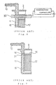
- Figs. 4 and 5 show a conventional fuel supply system disclosed in the International Publication No. WO96/23967.
- Fig. 4 is a sectional side view
- Fig. 5 is a plan view.
- Fig. 6 is an explanatory view of hot plate welding for forming a housing
- Fig. 7 is a sectional view taken along the line X-Y-Z.
- numeral 1 is a fuel tank
- numeral 2 is an opening of the fuel tank 1.
- a lid 3 made of a synthetic resin is formed so as to cover the opening 2, and a sealing gasket 4 is interposed between the lid 3 and the fuel tank 1.
- a fuel pump 5, a fuel filter 6, a pressure regulator 7, a fuel level gauge 8, an electric connector 9, and a discharge pipe 10 respectively serving as functional parts of a fuel supply system are integrally built in the lid 3 forming a unit.
- the fuel filter 6 is constructed such that a filtration element 12 is accommodated in a housing 11. Moreover, the lid 3 is a part of the housing 11, and the fuel filter 6 is suspended from the lid 3.
- the housing 11 is comprised of the lid 3 serving as an upper housing and a lower housing 13, and the lower housing 13 is molded of a synthetic resin material. the lid 3 and the lower housing 13 are welded fluid-tight at a boundary portion 14 over the whole circumference, and the filtration element 12 is disposed in the internal space.
- An intake pipe 15 serving as a fuel intake port is formed at an upper part on the inner circumferential side of the housing 11 of the fuel filter 6 and is connected to a discharge pipe of the fuel pump 5.
- a pipe 16 (indicated by the one-dot chain line in Fig. 4) forming a first fuel discharge port, among two fuel discharge ports of the housing 11, communicates to the discharge pipe 10 provided on the lid 3 and extends upward from a lower end of the lower housing 13.
- a return pipe 18 serving as a second fuel discharge port is formed at a lower portion of the lower housing 13 and is connected to the pressure regulator 7.
- the electric connector 8 integrally formed with the lid 3 is connected to a power source and a controller (not shown) outside of the fuel tank 1.
- the electric connector 8 is connected to the fuel pump 5 through a lead wire not shown, and supplies an electric power to a motor of the fuel pump 5.
- the electric connector 8 is connected to the fuel level gauge 8 (shown in Fig. 8) through a lead wire not shown and transmits an electric signal indicating a level of the fuel.
- the lower housing 13 is made of a conductive synthetic resin and discharges static electricity generated when the fuel passes through the filtration element 12 through the electric connector 8.
- the fuel pump 5 when an electric power is supplied to the fuel pump 5 through the electric connector 8, the fuel pump 5 sucks the fuel through a filter 19, raises a pressure of the fuel, and delivers the fuel to the intake pipe 15 located at the upper part on the inner circumferential side of the housing 11.
- the fuel flows through a passage 20 between the lower housing 13 and the lid 3 in the direction indicated by the arrow A.
- the fuel filter 6 the fuel flows downwards in the housing 11, whereby dust or the like in the fuel is filtered during the passage of the fuel through the filtration element 12.
- the fuel having passed through the filtration element 12, further passing through the discharge pipe 10, is supplied from the pipe 16 to an injector (not shown) of an engine fuel injection system.
- the pressure regulator 7 regulates the pressure of the fuel supplied to the injector so that the pressure may be constant, and a surplus fuel generated due to the change in consumption amount is returned from the pressure regulator 7 to the fuel tank 1.
- the lid 3 and the lower housing 13 are welded fluid-tight at the boundary portion 14 over the whole circumference, and hot plate welding is generally employed for the welding.
- hot plate welding as shown in Fig. 6, end faces of the lower housing 13 and the lid 3 to be welded are heated to a melting temperature with a heating plate 30 as a heating source. Then the heating plate 30 is removed, and the joining end faces of the lower housing 13 and the lid 3 are pressed to each other and heat-welded.
- an end portion of the molten portion is pushed out due to the pressing and forms a flash 21.
- the flash 21 varies in size and shape depending upon the state of melting of the joining end faces and the amount of the portion moved due to the pressing.
- the housing 11 varies in length.
- the flash 21 protruding at a portion serving as a fuel passage makes the passage area narrow and increases resistance of the passage.
- pulsation in the fuel flow applies a deformation stress to the flash 21, and a weak portion in the flash 21 sometimes drops due to fatigue fracture.
- the present invention was made to solve the above-discussed problems and has an object of providing a fuel supply system in which the housing is restrained from variation in longitudinal dimensions due to hot plate welding, the flash does not protrude into the passage, and even if any flash of the welded portion drops, the dropped flash does not flow into the passage.
- the housing for forming a passage for liquid fuel supplied from a fuel pump in a housing, the housing is formed fluid-tight by heat welding joining end faces of an upper housing and a lower housing both made of a synthetic resin, the upper housing and the lower housing are respectively provided with contact ribs facing each other at a tier lower down from the joining end faces, and the joining end faces are subject to melting, pressing and heat welding so that the contact ribs of the upper housing and the lower housing may come in contact with each other.
- the contact ribs are provided with space grooves interposed along the joining end faces, the space grooves being formed into a closed staying space at the time of completing the heat welding, and flash getting out at the time of heat welding is caused to stay in the staying space.
- the staying space formed by the contact ribs is provided at least in a passage downstream a filtration element.
- Fig. 1 is a sectional side view of a fuel supply system showing Embodiment 1 of the invention
- Fig. 2 is an explanatory view of hot plate welding for forming a housing according to the invention
- Fig. 3 is an enlarged partially sectional view of a welded portion.
- numerals 1 to 21 and 30 indicate the same parts as those in the foregoing description of the conventional system.
- the lid 3 and the lower housing 13 are made of a synthetic resin material.
- Numeral 3a is a joining end face of the lid 3 forming an upper portion of the housing 11
- numeral 3b is a contact rib provided along the joining end face 3a at a portion a little lower than the joining end face 3a
- numeral 3c is a space groove provided between the joining end face 3a and the contact rib 3b.
- Numeral 13a is a joining end face of the lower housing 13, and this joining end face 13a of the lower housing 13 and the joining end face 3a of the lid 3 are welded and formed into the boundary portion 14.
- End faces of a partition wall of the housing 11 perpendicular to the boundary portion 14 are the joining end faces 3a, 13a, and an outer shell of the housing 11 and a passage are formed fluid-tight by welding and joining the lid 3 and the lower housing 13 at the joining end faces 3a, 13a.
- Numeral 13b is a contact rib provided along the joining end face 13a at a portion a little lower than the joining end face 13a
- numeral 13c is a space groove provided between the joining end face 13a and the contact rib 13b.
- the joining end faces 3a, 13a and the contact ribs 3b, 13b of the lid 3 and the lower housing 13 are facing each other respectively.
- the heating plate 30 serving as the heating source is interposed between the joining end face 3a of the lid 3 and the joining end face 13a of the lower housing 13, and both of the joining end faces are heated to a melting temperature. Then the heating plate 30 is removed, and the joining end faces are pressed and welded fluid-tight together. In this process, since the contact ribs 3b, 13b of the lid 3 and the lower housing 13 are at a portion a little lower than the joining end faces 3a, 13a and are not heated up to a melting and softening temperature, the contact ribs 3b, 13b are not deformed by the pressing.
- deformation of the boundary portion 14 stops at a portion where the contact ribs 3b, 13b come in contact with each other, and the finished housing 11 has a constant length.
- a staying space 22 is formed by the space grooves 3c, 13c of the lid 3 and the lower housing 13.
- the flash 21, that is formed by pressing and deforming the joining end faces of the lid 3 and the lower housing 13 can be caused to remain in the staying space 22.
- forming the staying space 22 on the side where the fuel flows makes it possible to prevent the passage area from narrowing due to protruding of the flash 21 and restrain the flash 21 from dropping due to pulsation of the flowing liquid fuel. Even if the flash 21 drops, it is possible to prevent the downstream pipe from clogging by causing the flash 21 to remain in the staying space 22 so as not to flow downstream.
- the space grooves 3c, 13c and the contact ribs 3b, 13b may be the most preferable to provide the space grooves 3c, 13c and the contact ribs 3b, 13b on the circumference of the joining end faces. In this case, however, the sectional area of the fuel supply system becomes large, which is not desirable from the viewpoint of downsizing of the system. Therefore, it is also preferable that a portion not seriously affected by the flash 21 is dotted with the contact ribs 3b, 13b within a limited range in which the dimensions after the heat welding are constant. It is also preferable that the staying space 22 is formed only at a portion where dropping of the flash 21 influences the fuel system and the other parts remains in the same welding structure as in the prior art.
- the liquid fuel is supplied by driving the fuel pump 5 in the same manner as in the conventional system, and therefore further description thereof is omitted herein.
- the contact ribs 3b, 13b are provided with the space grooves 3c, 13c interposed along the joining end face 3a of the lid 3 and the joining end face 13a of the lower housing 13 at a portion lower than the joining end faces 3a, 13a.
- the space 22 formed on the passage side at the time of completing the welding causes to stay therein the flash 21 produced by the pressing and deformation process, thereby preventing the passage area from being narrowed, restraining the flash 21 from dropping due to the pulsation of the flowing liquid fuel, the flash 21 once dropped stays in the space 22, and the downstream pipe is prevented from clogging.
Landscapes
- Engineering & Computer Science (AREA)
- Chemical & Material Sciences (AREA)
- Mechanical Engineering (AREA)
- Chemical Kinetics & Catalysis (AREA)
- Combustion & Propulsion (AREA)
- General Engineering & Computer Science (AREA)
- Physics & Mathematics (AREA)
- Thermal Sciences (AREA)
- Lining Or Joining Of Plastics Or The Like (AREA)
- Fuel-Injection Apparatus (AREA)
- Cooling, Air Intake And Gas Exhaust, And Fuel Tank Arrangements In Propulsion Units (AREA)
- Filtration Of Liquid (AREA)
- Feeding And Controlling Fuel (AREA)
Abstract
Description
Claims (3)
- A fuel supply system in which a passage(16) for a liquid fuel supplied from a fuel pump(5) is formed in a housing(11), said passage being disposed being sunk into a fuel tank(1) integrally with a fuel pump and the housing, wherein said housing is formed fluid-tight by heat welding joining end faces (3a) (13a) of an upper housing (3) and a lower housing (13) both made of a synthetic resin, said upper housing and lower housing are respectively provided with contact ribs facing (3b) (13b) each other at a portion lower than the joining end faces(3a)(13a), and said joining end faces are subject to melting, pressing and heat welding so that both contact ribs may come in contact with each other.
- The fuel supply system according to claim 1, wherein the contact ribs (3b)(13b)are provided with space grooves (3c)(13c)interposed along the joining end faces, the space grooves being formed into a staying space(22) closed with said ribs at the time of completing the heat welding, and a flash getting out at the time of heat welding is caused to stay in the staying space(22).
- The fuel supply system according to claim 2, wherein the staying space(22) formed by the contact ribs(3b)(13b) is provided at least in a passage downstream a filtration element(12).
Applications Claiming Priority (1)
| Application Number | Priority Date | Filing Date | Title |
|---|---|---|---|
| PCT/JP2000/005527 WO2002016752A1 (en) | 2000-08-18 | 2000-08-18 | Fuel feed device |
Publications (3)
| Publication Number | Publication Date |
|---|---|
| EP1310663A1 true EP1310663A1 (en) | 2003-05-14 |
| EP1310663A4 EP1310663A4 (en) | 2004-06-02 |
| EP1310663B1 EP1310663B1 (en) | 2006-03-22 |
Family
ID=11736368
Family Applications (1)
| Application Number | Title | Priority Date | Filing Date |
|---|---|---|---|
| EP20000953483 Expired - Lifetime EP1310663B1 (en) | 2000-08-18 | 2000-08-18 | Fuel supply system |
Country Status (6)
| Country | Link |
|---|---|
| US (1) | US6729308B1 (en) |
| EP (1) | EP1310663B1 (en) |
| CN (1) | CN1215256C (en) |
| DE (1) | DE60026852T2 (en) |
| TW (1) | TW467997B (en) |
| WO (1) | WO2002016752A1 (en) |
Families Citing this family (11)
| Publication number | Priority date | Publication date | Assignee | Title |
|---|---|---|---|---|
| JP2002282620A (en) * | 2001-03-28 | 2002-10-02 | Kyosan Denki Co Ltd | Filter |
| JP2005297820A (en) * | 2004-04-13 | 2005-10-27 | Mitsubishi Motors Corp | Fuel tank |
| JP4340898B2 (en) * | 2004-11-17 | 2009-10-07 | 株式会社デンソー | Fuel supply device |
| JP4313289B2 (en) * | 2004-11-24 | 2009-08-12 | 本田技研工業株式会社 | Fuel tank pump module structure |
| JP5276848B2 (en) * | 2008-01-08 | 2013-08-28 | 株式会社ケーヒン | Fuel supply module |
| US7677225B2 (en) * | 2008-02-04 | 2010-03-16 | Kohler Co. | Fuel delivery system for engine |
| US9206777B2 (en) | 2012-10-26 | 2015-12-08 | Edelbrock, Llc | Fuel system conversions for carburetor to electronic fuel injection systems, methods of production thereof |
| US10851719B2 (en) | 2014-05-29 | 2020-12-01 | Cummins Power Generation Ip, Inc. | Systems for supplying fuel to fuel-injected engines in gensets |
| DE102015207137A1 (en) * | 2015-04-20 | 2016-10-20 | Robert Bosch Gmbh | Device for conveying fuel |
| US11203164B2 (en) * | 2016-02-11 | 2021-12-21 | Monoflo International, Inc. | Integrated weld stop |
| US12196160B2 (en) * | 2019-04-12 | 2025-01-14 | Auto Gas Services, LLC | Liquid injected propane fuel system |
Family Cites Families (12)
| Publication number | Priority date | Publication date | Assignee | Title |
|---|---|---|---|---|
| US5343902A (en) * | 1992-09-18 | 1994-09-06 | Solvay Automotive, Inc. | Internal gas removal system for fuel tank and method of making thereof |
| JPH08210212A (en) * | 1994-11-04 | 1996-08-20 | Nippondenso Co Ltd | Fuel feeding device |
| DE69532525T2 (en) * | 1995-02-03 | 2007-02-08 | Denso Corp., Kariya | FILTER |
| US5623907A (en) * | 1995-06-09 | 1997-04-29 | Walbro Corporation | Liquid propane fuel delivery system |
| US5769061A (en) * | 1996-04-01 | 1998-06-23 | Denso Corporation | Fuel supply system having a suction filter in a sub-tank |
| EP0969200B1 (en) * | 1997-03-11 | 2004-02-11 | Aisan Kogyo Kabushiki Kaisha | In-tank fuel filter improved to resist electrification |
| JP3130269B2 (en) * | 1997-05-30 | 2001-01-31 | 愛三工業株式会社 | Fuel supply device |
| FR2765632B1 (en) * | 1997-07-03 | 1999-09-24 | Marwal Systems | FUEL PUMP DEVICE FOR A MOTOR VEHICLE TANK |
| JP3967798B2 (en) * | 1997-08-29 | 2007-08-29 | 京三電機株式会社 | In-tank fuel filter |
| TW371699B (en) * | 1997-12-08 | 1999-10-11 | Mitsubishi Electric Corp | Fuel supply apparatus |
| JPH11200974A (en) * | 1998-01-07 | 1999-07-27 | Denso Corp | Fuel filter and in-tank fuel pump using the same |
| JP2002283455A (en) * | 2001-03-26 | 2002-10-03 | Kyosan Denki Co Ltd | Connecting structure of resin component |
-
2000
- 2000-08-18 DE DE2000626852 patent/DE60026852T2/en not_active Expired - Fee Related
- 2000-08-18 WO PCT/JP2000/005527 patent/WO2002016752A1/en not_active Ceased
- 2000-08-18 EP EP20000953483 patent/EP1310663B1/en not_active Expired - Lifetime
- 2000-08-18 US US10/110,694 patent/US6729308B1/en not_active Expired - Fee Related
- 2000-08-18 CN CNB008143552A patent/CN1215256C/en not_active Expired - Fee Related
- 2000-08-28 TW TW89117346A patent/TW467997B/en not_active IP Right Cessation
Also Published As
| Publication number | Publication date |
|---|---|
| CN1379844A (en) | 2002-11-13 |
| US6729308B1 (en) | 2004-05-04 |
| WO2002016752A1 (en) | 2002-02-28 |
| DE60026852D1 (en) | 2006-05-11 |
| DE60026852T2 (en) | 2006-11-16 |
| EP1310663A4 (en) | 2004-06-02 |
| TW467997B (en) | 2001-12-11 |
| CN1215256C (en) | 2005-08-17 |
| EP1310663B1 (en) | 2006-03-22 |
Similar Documents
| Publication | Publication Date | Title |
|---|---|---|
| US6729308B1 (en) | Fuel feed device | |
| US6923208B2 (en) | Fluid supply device | |
| US4321136A (en) | Fuel filtering device for engine | |
| US6062203A (en) | Apparatus for supplying fuel in an internal combustion engine | |
| US5649514A (en) | Fuel supply apparatus | |
| JP3758274B2 (en) | Fuel filter | |
| EP0939218B1 (en) | Fuel supply apparatus | |
| US8297260B2 (en) | Fuel supply system | |
| US20080217231A1 (en) | Component for a fluid filter, and fluid filter | |
| US20070175807A1 (en) | Liquid circuit | |
| US6655364B1 (en) | Fuel feed device | |
| JP6786606B2 (en) | Physical quantity detector | |
| US6029629A (en) | Constant fuel-pump-inlet pressure system | |
| US6305417B1 (en) | Reservoir for fuel feeding module, and fuel feeding module provided with the same | |
| KR20010067449A (en) | Fuel-delivery device for internal combustion engine in a vehicle | |
| US20100252651A1 (en) | Fuel injection apparatus | |
| US20140023115A1 (en) | Fuel property sensor | |
| US20070104589A1 (en) | Delivery unit that is mounted in a fuel tank | |
| EP1777407B1 (en) | Diesel filter | |
| JP2001214825A (en) | Fuel supply module for cars | |
| JPS6153547B2 (en) | ||
| JPWO2002016752A1 (en) | fuel supply device | |
| JP2005098212A (en) | Fuel filter | |
| JP4015936B2 (en) | Fuel supply device | |
| JPH1137010A (en) | Fuel filter and method for forming it |
Legal Events
| Date | Code | Title | Description |
|---|---|---|---|
| PUAI | Public reference made under article 153(3) epc to a published international application that has entered the european phase |
Free format text: ORIGINAL CODE: 0009012 |
|
| 17P | Request for examination filed |
Effective date: 20020415 |
|
| AK | Designated contracting states |
Designated state(s): AT BE CH CY DE DK ES FI FR GB GR IE IT LI LU MC NL PT SE |
|
| RBV | Designated contracting states (corrected) |
Designated state(s): AT BE CH DE FR GB LI |
|
| A4 | Supplementary search report drawn up and despatched |
Effective date: 20040421 |
|
| RIC1 | Information provided on ipc code assigned before grant |
Ipc: 7F 02M 37/22 B Ipc: 7F 02M 37/10 B Ipc: 7B 01D 35/027 A |
|
| 17Q | First examination report despatched |
Effective date: 20041230 |
|
| RTI1 | Title (correction) |
Free format text: FUEL SUPPLY SYSTEM |
|
| GRAP | Despatch of communication of intention to grant a patent |
Free format text: ORIGINAL CODE: EPIDOSNIGR1 |
|
| RBV | Designated contracting states (corrected) |
Designated state(s): DE FR GB |
|
| GRAS | Grant fee paid |
Free format text: ORIGINAL CODE: EPIDOSNIGR3 |
|
| GRAA | (expected) grant |
Free format text: ORIGINAL CODE: 0009210 |
|
| AK | Designated contracting states |
Kind code of ref document: B1 Designated state(s): DE FR GB |
|
| REG | Reference to a national code |
Ref country code: GB Ref legal event code: FG4D |
|
| RAP2 | Party data changed (patent owner data changed or rights of a patent transferred) |
Owner name: MITSUBISHI DENKI KABUSHIKI KAISHA |
|
| REF | Corresponds to: |
Ref document number: 60026852 Country of ref document: DE Date of ref document: 20060511 Kind code of ref document: P |
|
| REG | Reference to a national code |
Ref country code: GB Ref legal event code: 727 |
|
| REG | Reference to a national code |
Ref country code: GB Ref legal event code: 727A |
|
| ET | Fr: translation filed | ||
| PLBE | No opposition filed within time limit |
Free format text: ORIGINAL CODE: 0009261 |
|
| STAA | Information on the status of an ep patent application or granted ep patent |
Free format text: STATUS: NO OPPOSITION FILED WITHIN TIME LIMIT |
|
| REG | Reference to a national code |
Ref country code: GB Ref legal event code: 727B |
|
| 26N | No opposition filed |
Effective date: 20061227 |
|
| PGFP | Annual fee paid to national office [announced via postgrant information from national office to epo] |
Ref country code: DE Payment date: 20070816 Year of fee payment: 8 |
|
| PGFP | Annual fee paid to national office [announced via postgrant information from national office to epo] |
Ref country code: GB Payment date: 20070815 Year of fee payment: 8 |
|
| PGFP | Annual fee paid to national office [announced via postgrant information from national office to epo] |
Ref country code: FR Payment date: 20070808 Year of fee payment: 8 |
|
| GBPC | Gb: european patent ceased through non-payment of renewal fee |
Effective date: 20080818 |
|
| REG | Reference to a national code |
Ref country code: FR Ref legal event code: ST Effective date: 20090430 |
|
| PG25 | Lapsed in a contracting state [announced via postgrant information from national office to epo] |
Ref country code: FR Free format text: LAPSE BECAUSE OF NON-PAYMENT OF DUE FEES Effective date: 20080901 Ref country code: DE Free format text: LAPSE BECAUSE OF NON-PAYMENT OF DUE FEES Effective date: 20090303 |
|
| PG25 | Lapsed in a contracting state [announced via postgrant information from national office to epo] |
Ref country code: GB Free format text: LAPSE BECAUSE OF NON-PAYMENT OF DUE FEES Effective date: 20080818 |