EP1310636A2 - A System and Method for an Engine - Google Patents
A System and Method for an Engine Download PDFInfo
- Publication number
- EP1310636A2 EP1310636A2 EP02102505A EP02102505A EP1310636A2 EP 1310636 A2 EP1310636 A2 EP 1310636A2 EP 02102505 A EP02102505 A EP 02102505A EP 02102505 A EP02102505 A EP 02102505A EP 1310636 A2 EP1310636 A2 EP 1310636A2
- Authority
- EP
- European Patent Office
- Prior art keywords
- camshaft
- camshafts
- crankshaft
- phase angle
- faster rate
- Prior art date
- Legal status (The legal status is an assumption and is not a legal conclusion. Google has not performed a legal analysis and makes no representation as to the accuracy of the status listed.)
- Granted
Links
- 238000000034 method Methods 0.000 title claims abstract description 34
- 238000004519 manufacturing process Methods 0.000 claims description 5
- 230000003287 optical effect Effects 0.000 claims description 5
- 230000005355 Hall effect Effects 0.000 claims description 4
- 238000004590 computer program Methods 0.000 claims description 2
- 230000007246 mechanism Effects 0.000 description 31
- 239000000446 fuel Substances 0.000 description 13
- 238000002485 combustion reaction Methods 0.000 description 4
- 230000009977 dual effect Effects 0.000 description 4
- 239000012530 fluid Substances 0.000 description 3
- 238000002347 injection Methods 0.000 description 3
- 239000007924 injection Substances 0.000 description 3
- 238000005259 measurement Methods 0.000 description 3
- 230000006870 function Effects 0.000 description 2
- 230000000630 rising effect Effects 0.000 description 2
- 101100521334 Mus musculus Prom1 gene Proteins 0.000 description 1
- 206010044048 Tooth missing Diseases 0.000 description 1
- 238000013459 approach Methods 0.000 description 1
- 230000009286 beneficial effect Effects 0.000 description 1
- 230000008901 benefit Effects 0.000 description 1
- 238000010276 construction Methods 0.000 description 1
- 239000002826 coolant Substances 0.000 description 1
- 230000008878 coupling Effects 0.000 description 1
- 238000010168 coupling process Methods 0.000 description 1
- 238000005859 coupling reaction Methods 0.000 description 1
- 230000007423 decrease Effects 0.000 description 1
- 230000003247 decreasing effect Effects 0.000 description 1
- 238000010586 diagram Methods 0.000 description 1
- 239000002828 fuel tank Substances 0.000 description 1
- 239000007789 gas Substances 0.000 description 1
- 239000000203 mixture Substances 0.000 description 1
- 238000012986 modification Methods 0.000 description 1
- 230000004048 modification Effects 0.000 description 1
- 230000001360 synchronised effect Effects 0.000 description 1
Images



Classifications
-
- F—MECHANICAL ENGINEERING; LIGHTING; HEATING; WEAPONS; BLASTING
- F01—MACHINES OR ENGINES IN GENERAL; ENGINE PLANTS IN GENERAL; STEAM ENGINES
- F01L—CYCLICALLY OPERATING VALVES FOR MACHINES OR ENGINES
- F01L1/00—Valve-gear or valve arrangements, e.g. lift-valve gear
- F01L1/02—Valve drive
-
- F—MECHANICAL ENGINEERING; LIGHTING; HEATING; WEAPONS; BLASTING
- F01—MACHINES OR ENGINES IN GENERAL; ENGINE PLANTS IN GENERAL; STEAM ENGINES
- F01L—CYCLICALLY OPERATING VALVES FOR MACHINES OR ENGINES
- F01L1/00—Valve-gear or valve arrangements, e.g. lift-valve gear
- F01L1/34—Valve-gear or valve arrangements, e.g. lift-valve gear characterised by the provision of means for changing the timing of the valves without changing the duration of opening and without affecting the magnitude of the valve lift
Definitions
- Said step of indicating which one of said first and second camshafts has said faster rate of movement may include multiplying said phase angle difference value by a positive value if said first camshaft is being advanced or a negative value if said first camshaft is being retarded to obtain a first value wherein when said first value is greater than a predetermined threshold value said first camshaft has said faster rate of movement.
- the inventive system and method for selecting one of first and second camshafts of an engine solves the problem of which camshaft to use to reduce engine torque fluctuations.
- the inventive system and method selects the faster camshaft when modifying the speed of one of the camshafts to reduce engine torque fluctuations.
Landscapes
- Engineering & Computer Science (AREA)
- Mechanical Engineering (AREA)
- General Engineering & Computer Science (AREA)
- Combined Controls Of Internal Combustion Engines (AREA)
- Output Control And Ontrol Of Special Type Engine (AREA)
- Valve Device For Special Equipments (AREA)
Abstract
Description
- The invention relates to a system and method for selecting a camshaft in an engine having dual camshafts to reduce engine torque fluctuations.
- Known engines have utilized variable cam timing (VCT) mechanisms to control the opening and closing of intake valves and exhaust valves communicating with engine cylinders. In particular, each VCT mechanism is utilized to adjust a position of a camshaft (which actuates either an intake valve or exhaust valve or both) with respect to a crankshaft position. By varying the position of the camshaft (i.e., camshaft angle) with respect to the position of the crankshaft, engine fuel economy can be increased and engine emissions can be decreased.
- In known engines having VCT mechanisms, it is desired to shift the position of camshafts in the VCT mechanisms synchronously (i.e., at the same speed) to a desired phase angle with respect to the crankshaft. However, the inventors herein have recognized that first and second camshafts associated with first and second VCT mechanisms, respectively, in an engine, may not move to the desired phase angle at the same speed. For example, the first VCT mechanism may be actuated at a lower pressure that a second VCT mechanism due to a clogged oil line communicating with the first VCT, resulting in slower movement of the first camshaft. Still further, the first VCT mechanism may "stick" at cold temperatures resulting in slower movement of the first camshaft as compared to the second camshaft of the second VCT mechanism. During non-synchronous movement of the first and second camshafts, the air charge delivered to first and second cylinder banks, respectively, are different. The difference in air charge can result in a differing torques being produced by the first and second cylinder banks resulting in undesirable engine shaking and increased engine noise.
- It is an object of this invention to provide an improved system and method for and engine to reduce engine torque fluctuations.
- According to a first aspect of the invention there is provided a method for selecting one of first and second phase shiftable camshafts in a variable camshaft timing engine, said first and second camshafts controlling air flow communicating with said first and second cylinders, respectively, of said engine, said engine further including a crankshaft being driven by first and second pistons within said first and second cylinders, respectively, characterised in that the method comprises determining which of said first and second camshafts is moving at a faster rate of movement toward a first scheduled phase angle with respect to said crankshaft and selecting one of said first and second camshafts having said faster rate of movement for reducing engine torque fluctuations.
- Said determining step may include determining whether said first camshaft is being advanced or retarded with respect to a present position of said crankshaft, determining a phase angle difference between said first camshaft and said second camshaft with respect to said crankshaft and indicating which one of said first and second camshafts has said faster rate of movement based on said phase angle difference and whether said first camshaft is being advanced or retarded.
- Said step of determining whether said first camshaft is being advanced or retarded may include measuring a present phase angle of said first camshaft with respect to said crankshaft and comparing said present phase angle with a scheduled phase angle of said first camshaft.
- Said step of indicating which one of said first and second camshafts has said faster rate of movement may include multiplying said phase angle difference value by a positive value if said first camshaft is being advanced or a negative value if said first camshaft is being retarded to obtain a first value wherein when said first value is greater than a predetermined threshold value said first camshaft has said faster rate of movement.
- According to a second aspect of the invention there is provided a system for selecting one of first and second phase shiftable camshafts in a variable camshaft timing engine, said first and second camshafts controlling air flow communicating with first and second cylinders, respectively, of said engine, said engine further including a crankshaft being driven by first and second pistons within said first and second cylinders, respectively, characterised in that the system comprises a first sensor generating a first signal indicative of a position of said first camshaft, a second sensor generating a second signal indicative of a position of said second camshaft, a third sensor generating a third signal indicative of a position of said crankshaft and a controller configured to determine which of said first and second camshafts is moving toward a first scheduled phase angle with respect to said crankshaft at a faster rate of movement based on said first, second, and third signals, said controller being further configured to select one of said first and second camshafts having said faster rate of movement for reducing torque fluctuations when changing said faster rate of movement.
- Said first, second, and third sensors may comprise one of a Hall Effect sensor, an optical encoder and a variable reluctance sensor.
- According to a third aspect of the invention there is provided an article of manufacture comprising a computer storage medium having a computer program encoded therein for selecting one of first and second phase shiftable camshafts in a variable camshaft timing engine, said first and second camshafts controlling air flow communicating with said first and second cylinders, respectively, of said engine, said engine further including a crankshaft being driven by first and second pistons within said first and second cylinders, respectively characterised in that said computer storage medium comprises code for determining which of said first and second camshafts is moving at a faster rate of movement toward a first scheduled phase angle with respect to said crankshaft and code for selecting one of said first and second camshafts having said faster rate of movement for reducing torque fluctuations when changing said faster rate of movement.
- Said code for determining which of said first and second camshafts is moving at said faster rate may include code for determining whether said first camshaft is being advanced or retarded with respect to a present position of said camshaft, code for determining a phase angle difference between said first camshaft and said second camshaft with respect to said crankshaft and code for indicating which one of said first and second camshafts has said faster rate of movement based on said phase angle difference and whether said first camshaft is being advanced or retarded.
- Said code for determining whether said first camshaft is being advanced or retarded may includes code for determining a present phase angle of said first camshaft with respect to said crankshaft and code for comparing said present phase angle with said scheduled phase angle of said first camshaft.
- Said code for indicating which one of said first and second camshafts has said faster rate of movement may include code for multiplying said phase angle difference value by a positive value if said first camshaft is being advanced or a negative value if said first camshaft is being retarded to obtain a first value wherein when said first value is a greater than a predetermined threshold value said first camshaft has said faster rate of movement.
- According to a fourth aspect of the invention there is provided a motor vehicle having a system in accordance with said second aspect of the invention.
- The invention will now be described by way of example with reference to the accompanying drawing of which:-
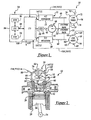
- Figure 1 is block diagram of an automotive vehicle having two variable cam timing mechanisms and a control system for controlling the mechanisms;
- Figure 2 is a cross-section view of one of the variable cam timing mechanisms shown in Figure 1;
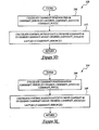
- Figures 3A-3E are flowcharts of a method of selecting a camshaft in one of dual variable cam timing mechanisms in an engine in accordance with the present invention;
- Figure 4 is a schematic of signals generated by a conventional control system for dual variable cam timing mechanisms; and
- Figures 5A-5B are schematics of signals generated by a control system for dual variable cam timing mechanisms in accordance with the present invention.
-
- Referring to the drawings, like reference numerals are used to identify identical components in the various views. Referring to Figure 1, an
automotive vehicle 10 having anengine 12 and acontrol system 14 is illustrated. -
Engine 12 includescylinder banks VCT mechanisms crankshaft 24. Referring to Figure 2, each ofcylinder banks cylinder bank 16 is shown along withVCT mechanism 20 for purposes of simplicity. - As illustrated,
engine 12 further includes acombustion chamber 26,cylinder walls 28, apiston 30, aspark plug 32, anintake manifold 34, anexhaust manifold 36, anintake valve 38, anexhaust valve 40, and afuel injector 42. - As used herein, the term "cylinder bank" refers to a related group of cylinders having one or more common characteristics, such as being located proximate one another or having a common emission control device (ECD), intake manifold, and/or exhaust manifold for example. This would include configurations having a group of cylinders on the same side of engine treated as a bank even though these cylinders may not share a common intake or exhaust manifold (i.e., the exhaust manifold could be configured with separate exhaust runners or branches if desired or beneficial). Similarly, cylinder banks can also be defined for in-line cylinder configurations which are within the scope of this invention.
- Referring to Figures 1 and 2,
VCT mechanisms cylinder banks VCT mechanism 20 is utilized to actuateintake valve 38 andexhaust valve 40 of a cylinder associated withcylinder bank 16 to control air flow entering the cylinder and exhaust gases exiting the cylinder, respectively. -
VCT mechanism 20 cooperates with acamshaft 44, which is shown communicating withrocker arms valves housing 52.Housing 52 forms atoothed cam wheel 54 havingteeth Housing 52 is hydraulically coupled to an inner shaft (not shown), which is in turn directly linked tocamshaft 44 via a timing chain (not shown). Therefore,housing 52 andcamshaft 44 rotate at a speed substantially equivalent to the inner camshaft. The inner camshaft rotates at a constant speed ratio tocrankshaft 24. - However, by manipulation of the hydraulic coupling as will be described later herein, the relative position of
camshaft 44 tocrankshaft 24 can be varied by hydraulic pressure inadvance chamber 68 andretard chamber 70. By allowing high-pressure hydraulic fluid to enteradvance chamber 68, the relative relationship betweencamshaft 44 andcrankshaft 24 is advanced. Thus,intake valve 38 andexhaust valve 40 open and close at a time earlier than normal relative tocrankshaft 24. - Similarly, by allowing high-pressure hydraulic fluid to enter
retard chamber 70, the relative relationship betweencamshaft 44 andcrankshaft 24 is retarded. Thus,intake valve 38 andexhaust valve 40 open and close at a time later than normal relative tocrankshaft 24. -
VCT mechanism 22 may include like components as illustrated forVCT mechanism 20 and may be hydraulically actuated as discussed above with reference tomechanism 20. In particular,VCT mechanism 22 includescam wheel 56 andteeth mechanism 22. -
Teeth cam wheel 54 are coupled tohousing 52 andcamshaft 44 and allow for measurement of relative position ofcamshaft 44 viacam timing sensor 80 which provides signal CAM_POS[1] to controller 84.Tooth 62 is used for cylinder identification. As illustrated,teeth cam wheel 54. - Similarly,
teeth cam wheel 56 are coupled tocam wheel 56 andcamshaft 46 and allow for measurement of relative position ofcamshaft 46 viacam timing sensor 82 which provides signal CAM_POS[2] to controller 84.Teeth cam wheel 56 may also be equally spaced around the perimeter ofwheel 56 for measurement of camshaft timing. - Referring to Figures 1 and 2,
controller 84 sends control signal LACT[1] to a conventional solenoid spool valve (not shown) to control the flow of hydraulic fluid either intoadvance chamber 68,retard chamber 70, or neither ofVCT mechanism 20. Similarly,controller 84 sends a control signal LACT[2] to another spool valve (not shown) to controlVCT mechanism 22. - Relative position of
camshaft 44 is measured in general terms, using the time, or rotation angle between the rising edge of a PIP signal (explained in greater detail below) and receiving a signal from one of theteeth - Similarly, the position of
camshaft 46 is measured using the time, or rotation angle between the rising edge of the PIP signal and receiving a signal from one of theteeth toothed cam wheel 54, a measured of cam timing for acamshaft 44 is received four times per revolution, with the extra signal used for cylinder identification. A detailed description of the method for determining relative position of thecamshafts - Referring to Figure 2, the
combustion chamber 26 communicates withintake manifold 34 and theexhaust manifold 36 via respective intake andexhaust valves - A
piston 30 is positioned withincombustion chamber 26 betweencylinder walls 28 and is connected tocrankshaft 24. Ignition of an air-fuel mixture withincombustion chamber 26 is controlled viaspark plug 32 which delivers ignition spark responsive to a signal from a distributorless ignition system (not shown). -
Intake manifold 34 is also shown havingfuel injector 42 coupled thereto for delivering fuel in proportion to the pulse width of signals (FPW) fromcontroller 84. Fuel is delivered tofuel injector 42 by a conventional fuel system (not shown) including a fuel tank, fuel pump, and fuel rail (now shown). Although port fuel injection is shown, direct fuel injection could be utilized instead of port fuel injection. - Referring to Figure 1,
control system 14 is provided to control the operation ofengine 12 and to implement a method for controllingVCT mechanisms Control system 14 includescamshaft position sensors crankshaft position sensor 86,ignition system controller 88, andengine controller 84. -
Camshaft position sensors camshafts Sensors - As
cam wheel 54 rotates,teeth engine 12 is a V8 engine for example) around thewheel 54 pass bysensor 80. Thesensor 80 senses the passing of each tooth and generates respective electric cam pulses or position signals CAM_POS[1] which are received bycontroller 84. Similarly, ascam wheel 56 rotates,teeth sensor 82 which generates respective electric cam pulses or position signals CAM_POS[2] which are received bycontroller 84. - The
crankshaft position sensor 86 is provided to generate a signal indicative of a position ofcrankshaft 24.Sensor 86 is conventional in the art and may comprise a hall effect sensor, an optical sensor, or a variable reluctance sensor. Acamshaft sprocket 90 is fixed tocrankshaft 24 and therefore rotates withcrankshaft 24.Sprocket 90 may include thirty-fivegear teeth 92 spaced ten degrees apart which results in one tooth missing thatsensor 86 uses for sensing the position ofsprocket 90. - The
sensor 86 generates position signal CS_POS that is transmitted toignition system controller 88.Controller 88 converts the signal CS_POS into the PIP signal which is then transmitted toengine controller 84. A PIP pulse occurs at evenly spaced rotational intervals ofcrankshaft 24 with one pulse per cylinder per engine cylinder cycle. This series of pulses comprise the PIP signal. - The
engine controller 84 is provided to implement the method for controllingVCT mechanisms camshafts controller 84 is provided to compare signal CAM_POS[1] to signal PIP to determine a relative position (i.e., phase angle) ofcamshaft 44 with respect tocrankshaft 24. Similarly,controller 84 compares signal CAM_POS[2] to signal PIP to determine a relative position ofcamshaft 46 with respect tocrankshaft 24. As illustrated,controller 84 includes aCPU 94 and a computer readable storage media comprising non-volatile and volatile storage in a read-only memory (ROM) 96 and a random-access memory (RAM) 98. - The computer readable media may be implemented using any of a number of known memory devices such as PROMs, EPROMs, EEPROMs, flash memory or any other electric, magnetic, optical or combination memory device capable of storing data, some of which represent executable instructions, used by
microprocessor 94 in controllingengine 12. - The
microprocessor 94 communicates with various sensors and actuators (discussed above) via an input/output (I/O)interface 100. Of course, the present invention could utilize more than one physical controller to provide engine/vehicle control depending upon the particular application. - Before discussing the method for controlling
VCT mechanisms - Referring to Figure 4 a scheduled camshaft position signal (Sched_camshaft_angle) for both
camshafts controller 84 is requesting that bothcamshafts crankshaft 24. As illustrated, the signal Camshaft_pos[1] represents the movement ofcamshaft 44 and signal Camshaft_pos[2] represents the movement ofcamshaft 46. As shown in this example, thecamshaft 44 is moving faster toward the desired phase angle than thecamshaft 46. As such, at time T = 1.35 seconds, the phase difference betweencamshafts - As discussed above, this phase difference can result in differing torques being produced by
cylinder banks - Referring to Figures 5A and 5B, the signals used by a method for controlling
camshafts - In Figure 5A, the signals Desired_camshaft_angle[1] represents a commanded position of
camshaft 44 over time toward a desired phase angle with respect tocrankshaft 24. - Similarly, Desired_camshaft_angle[2] represents a commanded position of
camshaft 46 over time toward a desired phase angle with respect tocrankshaft 24. In this example,controller 84 determines thatcrankshaft 24 is moving toward the desired phase angle at a faster rate thancrankshaft 24. - At time T=1.15 seconds when the phase difference between the
camshafts controller 84 decreases the value Desired_camshaft_angle[1] to slow movement of thefaster camshaft 44. Further, because thecrankshaft 24 is moving at a slower rate, the commanded position signal Desired_camshaft_angle[2] is not adjusted by the method and corresponds to the calculated Sched_camshaft_angle signal. - Thus, the rate of movement of the
faster crankshaft 24 approaches the rate of movement of theslower crankshaft 24 resulting in equivalent torques being produced in bothcylinder banks - Referring to Figure 3A, a
method 102 for controllingcamshafts step 104 determines a scheduled camshaft phase angle (Sched_camshaft_angle) based on engine operating parameters. Those skilled in the art will recognize that the desired camshaft phase angle forcamshafts engine 12 has a mechanically controlled throttle (not shown) controlling air flow intointake manifold 34,controller 84 may utilize a throttle position, engine speed, barometric pressure, air charge temperature, and coolant temperature to determine a scheduled camshaft phase angle from a lookup table. - Alternately, for example, when
engine 12 has an electronically controlled throttle (not shown) controlling air flow intomanifold 34,controller 84 may use an accelerator pedal position and a vehicle speed to determine the schedule camshaft phase angle from a lookup table. - Next at
step 106,controller 84 determines the current position (Camshaft_pos[1]) ofcamshaft 44, based on the signal CAM_POS[1] and the signal PIP. - Similarly, at
step 108,controller 84 determines the current position (Camshaft_pos[2]) ofcamshaft 46 based on the signal CAM_POS[2] and the signal PIP. - Next,
controller 84 simultaneously executessteps camshaft 44 andsteps camshaft 46. - The
step 110 determines a desired camshaft phase angle (Desired_camshaft_angle[1]) forcamshaft 44. - Referring to Figure 3B, the
underlying method 118 for implementingstep 110 will now be discussed. As shown,step 120 calculates the value (Camshaft_difference[1]) based on the following equation:camshafts - Camshaft_pos[1] represents the current position of
camshaft 44. - Next at
step 122, a determination is made as to whether Camshaft_difference[1] is greater than or equal to zero. If the answer to step 122 equals "Yes" indicatingcamshaft 44 is being advanced from a present position, a step 124 sets the value Direction_sign[1] equal to one. Otherwise,camshaft 44 is being retarded from a present position and astep 126 sets the value Direction_sign[1] equal to negative one. - Next at
step 128, an alternate camshaft angle forcamshaft 44 is calculated using the following equation:camshaft 44 corresponds to the position of thecamshaft 46 plus an offset. As will be discussed below, the value Alt_camshaft_angle[1] will only be used to controlcamshaft 44 if a phase difference betweencamshafts - Next at
step 130, an angular difference betweencamshafts - When Camshaft_bank_difference[1] is greater than a predetermined value, such zero for example, it indicates that
camshaft 44 is moving at a faster speed thancamshaft 46 toward the scheduled camshaft phase angle (Sched_camshaft_angle). - Alternately, when Camshaft_bank_difference[1] is less than the predetermined threshold value, it indicates that
camshaft 44 is moving at a slower speed thancamshaft 46 toward the scheduled camshaft phase angle (Sched_camshaft_angle). - Next at
step 132, a determination is made as to whether Camshaft_bank_difference[1] is greater than a value Camshaft_diff_threshold. The Camshaft_diff_threshold may be equal to a constant value such as 4° for example. When the value ofstep 132 equals "Yes", thestep 134 calculates the value Desired_camshaft_angle[1] using the following equation: - Otherwise, the
step 136 calculates the value Desired_camshaft_angle[1] using the following equation: - After either of
steps - Referring to Figure 3A, at
step 112, thecamshaft 44 is moved to a position represented by the value Desired_camshaft_angle[1]. Referring to Figure 3D, theunderlying method 138 for implementingstep 112 will now be discussed. Atstep 140, a camshaft position error is calculated using the following equation:
Camshaft _ error [1] = Desired _ camshaft _ angle [1] - Camshaft _ pos [1]] - Next at
step 142, control signal LACT[1] is calculated to movecamshaft 44 to Desired_camshaft_angle[1]. In particular, the signal LACT[1] is calculated as a function of the camshaft position error using the following equation: - After
step 142, themethod 138 is ended. - Referring to Figure 3A, the
steps camshaft 46. At step 114 a desired camshaft phase angle (Desired_camshaft_angle[2]) is determined forcamshaft 46. - Referring to Figure 3C, a
method 144 for implementingstep 114 will now be discussed. As shown,step 146 calculates the value Camshaft_difference[2] based on the following equation:camshaft 46. - Next at step 148, a determination is made as to whether Camshaft_difference[2] is greater than or equal to zero. If the answer to step 148 equals "Yes" indicating
camshaft 46 is being advanced from its present position, astep 150 sets the value Direction_sign[2] equal to one. Otherwise,camshaft 46 is being retarded from a present position and astep 152 sets the value Direction_sign[1] equal to negative one. - Next at
step 154, an alternate camshaft angle forcamshaft 46 is calculated using the following equation: - Thus, the value Alt_camshaft_angle[2] for
camshaft 46 corresponds to the position ofcamshaft 44 plus an offset. - Next at
step 156, an angular difference betweencamshafts - When Camshaft_bank_difference[2] is greater than a predetermined value, it indicates that
camshaft 46 is moving at a faster speed thancamshaft 44 toward the scheduled camshaft phase angle (Sched_camshaft_angle). Alternately, when Camshaft_bank_difference[2] is less than the predetermined value, it indicates thatcamshaft 46 is moving at a slower speed thancamshaft 44 toward the scheduled camshaft phase angle (Sched_camshaft_angle). - Next at
step 158, a determination is made as to whether Camshaft_bank_difference[2] is greater than the value Camshaft_diff_threshold. As discussed above, the Camshaft_diff_threshold may be equal to a constant value such as 4° for example. - When the value of
step 158 equals "Yes", thestep 160 calculates the value (Desired_camshaft_angle[2]) using the following equation: - Otherwise, the
step 162 calculates the value Desired_camshaft_angle[2] using the following equation: - After either of
steps - Referring to Figure 3A, at
step 116, thecamshaft 46 is moved to a position represented by the value Desired_camshaft_angle[2]. Referring to Figure 3E, theunderlying method 164 for implementingstep 116 will now be discussed. Atstep 166, a camshaft position error is calculated using the following equation: - Next at
step 168, control signal LACT[2] is calculated to movecamshaft 46 to Desired_camshaft_angle [2]. In particular, the signal LACT[2] is calculated as a function of the camshaft position error using the following equation:step 168, themethod 164 is ended. - The
control system 14 andmethod 102 for controllingcamshafts VCT mechanisms system 14 andmethod 102 selects the faster camshaft when modifying the speed of one of the camshafts to reduce engine torque fluctuations. - Therefore in summary, the inventive system and method for selecting one of first and second camshafts of an engine solves the problem of which camshaft to use to reduce engine torque fluctuations. In particular, the inventive system and method selects the faster camshaft when modifying the speed of one of the camshafts to reduce engine torque fluctuations.
- It will appreciate by the person skilled in the art that the invention is not limited to the specific embodiments described herein and that various modifications or alternative construction could be made without departing from the scope of the invention.
Claims (10)
- A method (102) for selecting one of first and second phase shiftable camshafts (44, 46) in a variable camshaft timing engine (10), said first and second camshafts (44, 46) controlling air flow communicating with said first and second cylinders, respectively, of said engine (10), said engine (10) further including a crankshaft (24) being driven by first and second pistons within said first and second cylinders, respectively, characterised in that the method comprises determining which of said first and second camshafts (44, 46) is moving at a faster rate of movement toward a first scheduled phase angle with respect to said crankshaft (24) and selecting one of said first and second camshafts (44, 46) having said faster rate of movement for reducing engine torque fluctuations.
- A method as claimed in claim 1 wherein said determining step includes determining whether said first camshaft (44) is being advanced or retarded with respect to a present position of said crankshaft (24), determining a phase angle difference between said first camshaft (44) and said second camshaft (46) with respect to said crankshaft (24) and indicating which one of said first and second camshafts (44 and 46) has said faster rate of movement based on said phase angle difference and whether said first camshaft (44) is being advanced or retarded.
- A method as claimed in claim 2 wherein said step of determining whether said first camshaft (44) is being advanced or retarded includes measuring a present phase angle of said first camshaft (44) with respect to said crankshaft (24) and comparing said present phase angle with a scheduled phase angle of said first camshaft (44).
- A method as claimed in claim 2 or in claim 3 wherein said step of indicating which one of said first and second camshafts (44 and 46) has said faster rate of movement includes multiplying said phase angle difference value by a positive value if said first camshaft (44) is being advanced or a negative value if said first camshaft (44) is being retarded to obtain a first value wherein when said first value is greater than a predetermined threshold value said first camshaft (44) has said faster rate of movement.
- A system for selecting one of first and second phase shiftable camshafts (44 and 46) in a variable camshaft timing engine (10), said first and second camshafts (44 and 46) controlling air flow communicating with first and second cylinders, respectively, of said engine (10), said engine (10) further including a crankshaft (24) being driven by first and second pistons within said first and second cylinders, respectively, characterised in that the system comprises a first sensor (80) generating a first signal indicative of a position of said first camshaft (44), a second sensor (82) generating a second signal indicative of a position of said second camshaft (46), a third sensor (86) generating a third signal indicative of a position of said crankshaft (24) and a controller (84) configured to determine which of said first and second camshafts (44 and 46) is moving toward a first scheduled phase angle with respect to said crankshaft (24) at a faster rate of movement based on said first, second, and third signals, said controller (84) being further configured to select one of said first and second camshafts (44 and 46) having said faster rate of movement for reducing torque fluctuations when changing said faster rate of movement.
- A system as claimed in claim 5 wherein said first, second, and third sensors (80,82 and 86) comprises one of a hall effect sensor, an optical encoder and or a variable reluctance sensor.
- An article of manufacture comprising a computer storage medium (96, 98) having a computer program encoded therein for selecting one of first and second phase shiftable camshafts (44 and 46) in a variable camshaft timing engine (10), said first and second camshafts (44 and 46) controlling air flow communicating with said first and second cylinders, respectively, of said engine (10), said engine (10) further including a crankshaft (24) being driven by first and second pistons within said first and second cylinders, respectively characterised in that said computer storage medium (96, 98) comprises code for determining which of said first and second camshafts (44 and 46) is moving at a faster rate of movement toward a first scheduled phase angle with respect to said crankshaft (24) and code for selecting one of said first and second camshafts (44 and 46) having said faster rate of movement for reducing torque fluctuations when changing said faster rate of movement.
- An article of manufacture as claimed in claim 7 wherein said code for determining which of said first and second camshafts (44 and 46) is moving at said faster rate includes code for determining whether said first camshaft is being advanced or retarded with respect to a present position of said camshaft, code for determining a phase angle difference between said first camshaft (44) and said second camshaft (46) with respect to said crankshaft (24) and code for indicating which one of said first and second camshafts (44 and 46) has said faster rate of movement based on said phase angle difference and whether said first camshaft (44) is being advanced or retarded.
- An article of manufacture as claimed in claim 8 wherein said code for determining whether said first camshaft (44) is being advanced or retarded includes code for determining a present phase angle of said first camshaft (44) with respect to said crankshaft (24) and code for comparing said present phase angle with said scheduled phase angle of said first camshaft (44).
- An article manufacture as claimed in claim 8 or in claim 9 wherein said code for indicating which one of said first and second camshafts (44 and 46) has said faster rate of movement includes code for multiplying said phase angle difference value by a positive value if said first camshaft (44) is being advanced or a negative value if said first camshaft (44) is being retarded to obtain a first value wherein when said first value is a greater than a predetermined threshold value said first camshaft (44) has said faster rate of movement.
Applications Claiming Priority (2)
| Application Number | Priority Date | Filing Date | Title |
|---|---|---|---|
| US45228 | 2001-11-09 | ||
| US10/045,228 US6650992B2 (en) | 2001-11-09 | 2001-11-09 | System and method for selecting a camshaft in an engine having dual camshafts |
Publications (3)
| Publication Number | Publication Date |
|---|---|
| EP1310636A2 true EP1310636A2 (en) | 2003-05-14 |
| EP1310636A3 EP1310636A3 (en) | 2007-01-10 |
| EP1310636B1 EP1310636B1 (en) | 2010-06-30 |
Family
ID=21936710
Family Applications (1)
| Application Number | Title | Priority Date | Filing Date |
|---|---|---|---|
| EP02102505A Expired - Lifetime EP1310636B1 (en) | 2001-11-09 | 2002-10-27 | A System and Method for an Engine |
Country Status (3)
| Country | Link |
|---|---|
| US (1) | US6650992B2 (en) |
| EP (1) | EP1310636B1 (en) |
| DE (1) | DE60236838D1 (en) |
Families Citing this family (13)
| Publication number | Priority date | Publication date | Assignee | Title |
|---|---|---|---|---|
| JP2004308652A (en) * | 2003-04-07 | 2004-11-04 | Robert Bosch Gmbh | Combustion engine with device for detecting absolute rotation angle of crankshaft |
| US20080172160A1 (en) * | 2003-09-05 | 2008-07-17 | Borgwarner Inc. | Method to measure VCT phase by tracking the absolute angular positions of the camshaft and the crankshaft |
| US6994061B2 (en) * | 2003-11-13 | 2006-02-07 | Ford Global Technologies, Llc | Computer readable storage medium for use with engine having variable valve actuator during degradation |
| US6938593B2 (en) * | 2003-11-13 | 2005-09-06 | Ford Global Technologies, Llc | Computer readable storage medium for use with engine having variable valve actuator |
| JP2007530872A (en) * | 2004-03-29 | 2007-11-01 | サウスウエスト リサーチ インスティテュート | Engine crankshaft position recognition and tracking method applicable to cam and crankshaft signals with arbitrary patterns |
| US7188021B2 (en) * | 2004-10-25 | 2007-03-06 | Litens Automotive Partnership | Angular position sensor-based engine controller system |
| US7866302B2 (en) * | 2004-10-25 | 2011-01-11 | Litens Automotive Partnership | Method and system for starting or restarting an internal combustion engine via selective combustion |
| US7558669B2 (en) * | 2004-10-25 | 2009-07-07 | Litens Automotive Partnership | Engine controller system and method employing high speed angular position sensor |
| WO2006045181A1 (en) * | 2004-10-25 | 2006-05-04 | Litens Automotive Partnership | System and method for measuring torsional vibrations in an engine and managing operation of the engine to reduce those vibrations |
| US8791645B2 (en) * | 2006-02-10 | 2014-07-29 | Honeywell International Inc. | Systems and methods for controlling light sources |
| US7779802B2 (en) * | 2007-07-11 | 2010-08-24 | Ford Global Technologies, Llc | Simulated cam position for a V-type engine |
| KR100980865B1 (en) * | 2007-12-14 | 2010-09-10 | 기아자동차주식회사 | Variable Valve Timing Mechanism Control Method |
| JP7345063B2 (en) * | 2020-05-27 | 2023-09-14 | 日立Astemo株式会社 | Control device |
Citations (3)
| Publication number | Priority date | Publication date | Assignee | Title |
|---|---|---|---|---|
| US5245968A (en) | 1992-08-04 | 1993-09-21 | Ford Motor Company | System to determine cam phase and cylinder identification for a variable cam timing engine |
| US5522352A (en) | 1994-02-04 | 1996-06-04 | Nippondenso Co., Ltd. | Valve timing control system for engines |
| JPH08338209A (en) | 1995-06-14 | 1996-12-24 | Mitsubishi Motors Corp | V type engine |
Family Cites Families (3)
| Publication number | Priority date | Publication date | Assignee | Title |
|---|---|---|---|---|
| GB2268570B (en) * | 1989-10-13 | 1994-03-30 | Rover Group | An internal combustion engine camshaft drive mechanism |
| JPH04136404A (en) * | 1990-09-28 | 1992-05-11 | Toyota Motor Corp | Valve timing control device |
| US6219611B1 (en) | 1999-10-18 | 2001-04-17 | Ford Global Technologies, Inc. | Control method for engine having multiple control devices |
-
2001
- 2001-11-09 US US10/045,228 patent/US6650992B2/en not_active Expired - Fee Related
-
2002
- 2002-10-27 EP EP02102505A patent/EP1310636B1/en not_active Expired - Lifetime
- 2002-10-27 DE DE60236838T patent/DE60236838D1/en not_active Expired - Lifetime
Patent Citations (3)
| Publication number | Priority date | Publication date | Assignee | Title |
|---|---|---|---|---|
| US5245968A (en) | 1992-08-04 | 1993-09-21 | Ford Motor Company | System to determine cam phase and cylinder identification for a variable cam timing engine |
| US5522352A (en) | 1994-02-04 | 1996-06-04 | Nippondenso Co., Ltd. | Valve timing control system for engines |
| JPH08338209A (en) | 1995-06-14 | 1996-12-24 | Mitsubishi Motors Corp | V type engine |
Also Published As
| Publication number | Publication date |
|---|---|
| EP1310636A3 (en) | 2007-01-10 |
| DE60236838D1 (en) | 2010-08-12 |
| US20030093214A1 (en) | 2003-05-15 |
| US6650992B2 (en) | 2003-11-18 |
| EP1310636B1 (en) | 2010-06-30 |
Similar Documents
| Publication | Publication Date | Title |
|---|---|---|
| US7398762B2 (en) | Vehicle control system | |
| US7077085B2 (en) | Variable valve control system and method for multi-cylinder internal combustion engine | |
| US7290527B2 (en) | Vehicle control system | |
| US6650992B2 (en) | System and method for selecting a camshaft in an engine having dual camshafts | |
| US10316765B2 (en) | Control device and control method for internal combustion engine | |
| US20060112927A1 (en) | Engine method | |
| US7762242B2 (en) | Exhaust gas recirculation valve | |
| US6817336B2 (en) | Intake manifold pressure control for variable displacement engines | |
| JP2006257958A (en) | Cam phase sensor, variable valve timing mechanism control device, and variable valve timing mechanism control method | |
| US6842691B2 (en) | Cam synchronization algorithm for engine with variable cam timing | |
| EP1418329B1 (en) | A method and system for controlling an engine | |
| US7082923B2 (en) | Idling speed control system and method | |
| US7779802B2 (en) | Simulated cam position for a V-type engine | |
| US6647335B2 (en) | System and method for controlling dual camshafts in a variable cam timing engine | |
| AU2006321140B2 (en) | Variable valve timing apparatus | |
| JP2008274822A (en) | Control device for internal combustion engine | |
| JP2021124022A (en) | Control device for internal combustion engine | |
| US20070144487A1 (en) | Control system and timing rotor for multi-cylinder internal combustion engine | |
| JPS62135665A (en) | Device for controlling ignition timing of internal combustion engine | |
| JP2001303992A (en) | Valve timing control method for DOHC engine |
Legal Events
| Date | Code | Title | Description |
|---|---|---|---|
| PUAI | Public reference made under article 153(3) epc to a published international application that has entered the european phase |
Free format text: ORIGINAL CODE: 0009012 |
|
| AK | Designated contracting states |
Designated state(s): AT BE BG CH CY CZ DE DK EE ES FI FR GB GR IE IT LI LU MC NL PT SE SK TR |
|
| AX | Request for extension of the european patent |
Extension state: AL LT LV MK RO SI |
|
| REG | Reference to a national code |
Ref country code: IE Ref legal event code: FG4D Free format text: GERMAN |
|
| PUAL | Search report despatched |
Free format text: ORIGINAL CODE: 0009013 |
|
| AK | Designated contracting states |
Kind code of ref document: A3 Designated state(s): AT BE BG CH CY CZ DE DK EE ES FI FR GB GR IE IT LI LU MC NL PT SE SK TR |
|
| AX | Request for extension of the european patent |
Extension state: AL LT LV MK RO SI |
|
| RIC1 | Information provided on ipc code assigned before grant |
Ipc: F01L 1/34 20060101AFI20061201BHEP |
|
| 17P | Request for examination filed |
Effective date: 20070614 |
|
| AKX | Designation fees paid |
Designated state(s): DE GB |
|
| 17Q | First examination report despatched |
Effective date: 20091016 |
|
| GRAP | Despatch of communication of intention to grant a patent |
Free format text: ORIGINAL CODE: EPIDOSNIGR1 |
|
| GRAS | Grant fee paid |
Free format text: ORIGINAL CODE: EPIDOSNIGR3 |
|
| GRAA | (expected) grant |
Free format text: ORIGINAL CODE: 0009210 |
|
| AK | Designated contracting states |
Kind code of ref document: B1 Designated state(s): DE GB |
|
| REG | Reference to a national code |
Ref country code: GB Ref legal event code: FG4D |
|
| REF | Corresponds to: |
Ref document number: 60236838 Country of ref document: DE Date of ref document: 20100812 Kind code of ref document: P |
|
| PGFP | Annual fee paid to national office [announced via postgrant information from national office to epo] |
Ref country code: GB Payment date: 20100923 Year of fee payment: 9 |
|
| PGFP | Annual fee paid to national office [announced via postgrant information from national office to epo] |
Ref country code: DE Payment date: 20101029 Year of fee payment: 9 |
|
| PLBE | No opposition filed within time limit |
Free format text: ORIGINAL CODE: 0009261 |
|
| STAA | Information on the status of an ep patent application or granted ep patent |
Free format text: STATUS: NO OPPOSITION FILED WITHIN TIME LIMIT |
|
| 26N | No opposition filed |
Effective date: 20110331 |
|
| REG | Reference to a national code |
Ref country code: DE Ref legal event code: R097 Ref document number: 60236838 Country of ref document: DE Effective date: 20110330 |
|
| GBPC | Gb: european patent ceased through non-payment of renewal fee |
Effective date: 20111027 |
|
| PG25 | Lapsed in a contracting state [announced via postgrant information from national office to epo] |
Ref country code: DE Free format text: LAPSE BECAUSE OF NON-PAYMENT OF DUE FEES Effective date: 20120501 |
|
| REG | Reference to a national code |
Ref country code: DE Ref legal event code: R119 Ref document number: 60236838 Country of ref document: DE Effective date: 20120501 |
|
| PG25 | Lapsed in a contracting state [announced via postgrant information from national office to epo] |
Ref country code: GB Free format text: LAPSE BECAUSE OF NON-PAYMENT OF DUE FEES Effective date: 20111027 |