EP1310631A2 - Apparatus and method for locating a fluid interface - Google Patents
Apparatus and method for locating a fluid interface Download PDFInfo
- Publication number
- EP1310631A2 EP1310631A2 EP02291077A EP02291077A EP1310631A2 EP 1310631 A2 EP1310631 A2 EP 1310631A2 EP 02291077 A EP02291077 A EP 02291077A EP 02291077 A EP02291077 A EP 02291077A EP 1310631 A2 EP1310631 A2 EP 1310631A2
- Authority
- EP
- European Patent Office
- Prior art keywords
- electrodes
- fluids
- interface
- resistor
- locating
- Prior art date
- Legal status (The legal status is an assumption and is not a legal conclusion. Google has not performed a legal analysis and makes no representation as to the accuracy of the status listed.)
- Granted
Links
Images
Classifications
-
- G—PHYSICS
- G01—MEASURING; TESTING
- G01F—MEASURING VOLUME, VOLUME FLOW, MASS FLOW OR LIQUID LEVEL; METERING BY VOLUME
- G01F23/00—Indicating or measuring liquid level or level of fluent solid material, e.g. indicating in terms of volume or indicating by means of an alarm
- G01F23/22—Indicating or measuring liquid level or level of fluent solid material, e.g. indicating in terms of volume or indicating by means of an alarm by measuring physical variables, other than linear dimensions, pressure or weight, dependent on the level to be measured, e.g. by difference of heat transfer of steam or water
- G01F23/24—Indicating or measuring liquid level or level of fluent solid material, e.g. indicating in terms of volume or indicating by means of an alarm by measuring physical variables, other than linear dimensions, pressure or weight, dependent on the level to be measured, e.g. by difference of heat transfer of steam or water by measuring variations of resistance of resistors due to contact with conductor fluid
-
- E—FIXED CONSTRUCTIONS
- E21—EARTH OR ROCK DRILLING; MINING
- E21B—EARTH OR ROCK DRILLING; OBTAINING OIL, GAS, WATER, SOLUBLE OR MELTABLE MATERIALS OR A SLURRY OF MINERALS FROM WELLS
- E21B47/00—Survey of boreholes or wells
- E21B47/04—Measuring depth or liquid level
- E21B47/047—Liquid level
-
- G—PHYSICS
- G01—MEASURING; TESTING
- G01F—MEASURING VOLUME, VOLUME FLOW, MASS FLOW OR LIQUID LEVEL; METERING BY VOLUME
- G01F23/00—Indicating or measuring liquid level or level of fluent solid material, e.g. indicating in terms of volume or indicating by means of an alarm
- G01F23/22—Indicating or measuring liquid level or level of fluent solid material, e.g. indicating in terms of volume or indicating by means of an alarm by measuring physical variables, other than linear dimensions, pressure or weight, dependent on the level to be measured, e.g. by difference of heat transfer of steam or water
- G01F23/24—Indicating or measuring liquid level or level of fluent solid material, e.g. indicating in terms of volume or indicating by means of an alarm by measuring physical variables, other than linear dimensions, pressure or weight, dependent on the level to be measured, e.g. by difference of heat transfer of steam or water by measuring variations of resistance of resistors due to contact with conductor fluid
- G01F23/241—Indicating or measuring liquid level or level of fluent solid material, e.g. indicating in terms of volume or indicating by means of an alarm by measuring physical variables, other than linear dimensions, pressure or weight, dependent on the level to be measured, e.g. by difference of heat transfer of steam or water by measuring variations of resistance of resistors due to contact with conductor fluid for discrete levels
- G01F23/242—Mounting arrangements for electrodes
Definitions
- the present invention relates to the monitoring of the location of the interface between two different fluids.
- the invention provides new techniques for the permanent location of the fluid interface between two fluids with different resistivities, for example during the drilling of a cavern in the underground formations, in order to store energy therein.
- a known technique to build up gas storage caverns of precisely controlled geometry consists in injecting water from the surface in a tubing, circulating said water in the salt formation and returning the brine to the surface in the annulus between said tubing and a string.
- a diesel cushion is kept between the oversatured brine and the surface in order to control the water level in real time.
- Monitoring in real time the depth of the brine/diesel interface thus controls the cavern shape.
- the known interface monitoring method involves a density measurement with a nuclear logging tool. Unfortunately, this method is incompatible with the drilling method previously explained, because of space constraints. Furthermore, due to the corrosive environment, the chemical and mechanical resistances of the interface monitoring apparatus need to be particularly reliable.
- the location of said interface is achieved by deploying an array of electrodes in the fluids of different resistivities.
- the network comprises a set of passive electrical electrodes evenly spaced and connected in series, a fixed resistor being inserted in this array between each electrode and the next one.
- any conductive fluid will short-circuit the electrical resistance between two consecutive electrodes and consequently decrease the total resistance of global electrical circuit.
- a permanent measurement of said total resistance will thus provide the depth of the interface.
- This method will be very efficient to determine the interface level between a conductive fluid (for example brine or water) and a non-conductive fluid (for example oil or diesel).
- the electrodes network and the electrical cable connecting said electrodes to each other are encased in a highly corrosion resistant vessel, all parts being welded.
- the installation is thus designed with a very high level of reliability, as it must be operational for continuous applications.
- a method for locating the interface between two fluids of different resistivities, said fluids being located in an underground formation comprising:
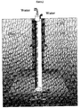
- Figure 1 shows schematically the manner in which a salt cavern suitable for gas storage can be formed.
- a borehole is drilled into the salt formation and cased (9 5/8 inch casing) to a point level with the desired top of the cavern.
- Tubing (7 5/8 inch tubing) is lowered into the well and a delivery tubing positioned inside the tubing.
- the annulus between the tubing and the well is then filled with diesel.
- Water is pumped to the well bottom through the delivery tubing where it dissolves the salt and returns to the surface via the 7 5/8 tubing.
- the presence of the diesel cap over the water layer prevents the cavern extending vertically too fast and so allows radial development of the cavern to define a useful shape and volume.
- the brine diesel interface therefore corresponds to the vertical extent of the cavern.
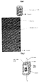
- Figure 2 represents a schematic of an installation according to one embodiment of the invention.
- said installation aims at locating the fluid interface between a salt saturated brine layer and a diesel layer, said brine layer being situated under said diesel layer, due to their density differences.
- the brine layer and the diesel layer are located in an underground formation.
- a metal casing covers the walls of said underground formation.
- the installation of the invention can locate the interface between any fluids of different resistivities.
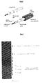
- the installation being the subject of this invention is composed of the following items, described below as they will appear from the bottom of the underground formation to the surface:
- the installation according to the invention creates an electrical circuit that permits to locate the interface between two fluids of different resistivities.
- any conductive fluid will short-circuit the electrical resistance between two consecutive electrodes and decrease the total resistance of the electrical circuit.
- a permanent measurement of this total resistance will provide the depth of the interface. Consequently, in an application with brine and diesel, as by nature the two fluids are segregated in the well, with the brine at the bottom and the diesel on top, a simple measurement of the total electrical resistance of the array will provide the depth of the interface.
Landscapes
- Physics & Mathematics (AREA)
- Fluid Mechanics (AREA)
- Geology (AREA)
- Thermal Sciences (AREA)
- General Physics & Mathematics (AREA)
- Life Sciences & Earth Sciences (AREA)
- Engineering & Computer Science (AREA)
- Mining & Mineral Resources (AREA)
- Geophysics (AREA)
- Environmental & Geological Engineering (AREA)
- General Life Sciences & Earth Sciences (AREA)
- Geochemistry & Mineralogy (AREA)
- Geophysics And Detection Of Objects (AREA)
- Investigating Or Analyzing Materials By The Use Of Electric Means (AREA)
- Sampling And Sample Adjustment (AREA)
- Investigating Or Analysing Biological Materials (AREA)
Abstract
Description
- fixing at least two electrodes along said underground formation;
- connecting in series a resistor between said two electrodes;
- mechanically and electrically linking said electrodes and resistor with an encased cable;
- connecting said encased cable to a surface resistance meter;
- measuring the total resistance between said two electrodes with said surface resistance meter;
- locating said interface between said two fluids of different resistivities from said total resistance measurement.
- a pressure vessel comprising at least two electrodes and a resistor, said resistor being placed between said two electrodes;
- an electrical cable connecting in series said electrodes and resistor;
- a resistance meter electrically connected to said electrical cable.
- an array of at least two electrodes along the cavern area. For example, if the cavern is approximately 160 m. high, 6 electrodes evenly spaced every 10 meters could cover the bottom 60 meters followed by 20 electrodes evenly spaced every 10 meters. The electrodes are electrically and mechanically linked with a permanent downhole encased cable.
- a permanent downhole encased cable to link the array of the electrodes to the surface.
- a computerized PC based resistance meter that is known in the state of the art.
Claims (3)
- A method for locating the interface between two fluids of different resistivities, said fluids being located in an underground formation, said method comprising:fixing at least two electrodes along said underground formation;connecting in series a resistor between said two electrodes;mechanically and electrically linking said electrodes and resistor with an encased cable;connecting said encased cable to a surface resistance meter;measuring the total resistance between said two electrodes with said surface resistance meter;locating said interface between said two fluids of different resistivities from said total resistance measurement.
- An installation for locating the interface between two fluids of different resistivities, said fluids being located in an underground formation, said installation comprising:a pressure vessel comprising at least two electrodes and a resistor, said resistor being placed between said two electrodes;an electrical cable connecting in series said electrodes and resistor;a resistance meter electrically connected to said electrical cable.
- The installation according to claim 2, wherein said electrodes are placed in the center of said pressure vessel and insulated from said pressure vessel body with an insulating material.
Applications Claiming Priority (2)
| Application Number | Priority Date | Filing Date | Title |
|---|---|---|---|
| GBGB0112934.5A GB0112934D0 (en) | 2001-05-26 | 2001-05-26 | Methods and installation for fluid interface monitoring |
| GB0112934 | 2001-05-26 |
Publications (3)
| Publication Number | Publication Date |
|---|---|
| EP1310631A2 true EP1310631A2 (en) | 2003-05-14 |
| EP1310631A3 EP1310631A3 (en) | 2004-03-10 |
| EP1310631B1 EP1310631B1 (en) | 2006-06-28 |
Family
ID=9915421
Family Applications (1)
| Application Number | Title | Priority Date | Filing Date |
|---|---|---|---|
| EP02291077A Expired - Lifetime EP1310631B1 (en) | 2001-05-26 | 2002-04-29 | Apparatus and method for locating a fluid interface |
Country Status (4)
| Country | Link |
|---|---|
| EP (1) | EP1310631B1 (en) |
| AT (1) | ATE331871T1 (en) |
| DE (1) | DE60212787T2 (en) |
| GB (1) | GB0112934D0 (en) |
Cited By (3)
| Publication number | Priority date | Publication date | Assignee | Title |
|---|---|---|---|---|
| EP2681593A4 (en) * | 2011-03-02 | 2015-08-12 | Genscape Intangible Holding Inc | METHOD AND SYSTEM FOR DETERMINING THE QUANTITY OF A LIQUID ENERGY PRODUCT LOCATED IN A STORAGE IN A GROUNDWATER CAVE |
| CN110056318A (en) * | 2019-04-23 | 2019-07-26 | 中工国际工程股份有限公司 | A kind of salt hole air reserved storeroom row halogen pipe preventing clogging up device |
| US11719097B2 (en) | 2021-10-29 | 2023-08-08 | Halliburton Energy Services, Inc. | Systems and methods for production and reservoir monitoring |
Families Citing this family (1)
| Publication number | Priority date | Publication date | Assignee | Title |
|---|---|---|---|---|
| CN116067453B (en) * | 2023-03-03 | 2023-06-20 | 华中科技大学 | A gas storage ranging system and method for magnetically coupled multi-phase state admittance identification |
Family Cites Families (6)
| Publication number | Priority date | Publication date | Assignee | Title |
|---|---|---|---|---|
| DE2621142C3 (en) * | 1976-05-13 | 1980-10-09 | Kavernen Bau- Und Betriebs-Gesellschaft Mbh, 3000 Hannover | Method and device for determining the depth of the blanket medium salt brine separation level in the construction of caverns |
| CH632089A5 (en) * | 1978-06-15 | 1982-09-15 | Alusuisse | Filling level measuring probe for an electrically conductive medium |
| DD140683A1 (en) * | 1978-12-13 | 1980-03-19 | Peter Hoerig | DEVICE FOR THE TEXT DETERMINATION OF THE MIRROR OF AN ELECTROLYTIC FLUID UNDERGROUND |
| SU1154447A1 (en) * | 1983-07-13 | 1985-05-07 | Ивано-Франковский Институт Нефти И Газа | Deep-well level gauge |
| DE3824663A1 (en) * | 1988-07-15 | 1989-01-05 | Wolfgang Prof Dr Ing Thelen | Device for continuous level measurement in liquids, by means of a chain of series- or parallel-connected, temperature-dependent resistors, which are heated by an electrical current |
| DE4121796A1 (en) * | 1991-07-02 | 1993-01-14 | Preussag Erdoel Und Erdgas Gmb | Electrically conductive fluid level indicator esp. for brine level in salt pit - has electrodes in parallel with high-ohm resistances for long life under high pressure and temp. |
-
2001
- 2001-05-26 GB GBGB0112934.5A patent/GB0112934D0/en not_active Ceased
-
2002
- 2002-04-29 EP EP02291077A patent/EP1310631B1/en not_active Expired - Lifetime
- 2002-04-29 DE DE60212787T patent/DE60212787T2/en not_active Expired - Lifetime
- 2002-04-29 AT AT02291077T patent/ATE331871T1/en not_active IP Right Cessation
Cited By (4)
| Publication number | Priority date | Publication date | Assignee | Title |
|---|---|---|---|---|
| EP2681593A4 (en) * | 2011-03-02 | 2015-08-12 | Genscape Intangible Holding Inc | METHOD AND SYSTEM FOR DETERMINING THE QUANTITY OF A LIQUID ENERGY PRODUCT LOCATED IN A STORAGE IN A GROUNDWATER CAVE |
| CN110056318A (en) * | 2019-04-23 | 2019-07-26 | 中工国际工程股份有限公司 | A kind of salt hole air reserved storeroom row halogen pipe preventing clogging up device |
| CN110056318B (en) * | 2019-04-23 | 2023-12-22 | 中工国际工程股份有限公司 | Anti-blocking device for brine discharge pipe of salt cavern gas storage |
| US11719097B2 (en) | 2021-10-29 | 2023-08-08 | Halliburton Energy Services, Inc. | Systems and methods for production and reservoir monitoring |
Also Published As
| Publication number | Publication date |
|---|---|
| ATE331871T1 (en) | 2006-07-15 |
| EP1310631B1 (en) | 2006-06-28 |
| EP1310631A3 (en) | 2004-03-10 |
| DE60212787T2 (en) | 2007-06-28 |
| GB0112934D0 (en) | 2001-07-18 |
| DE60212787D1 (en) | 2006-08-10 |
Similar Documents
| Publication | Publication Date | Title |
|---|---|---|
| US5353873A (en) | Apparatus for determining mechanical integrity of wells | |
| AU784759B2 (en) | Method and apparatus for monitoring the advance of seawater into fresh water aquifers near coastal cities | |
| CA2834079C (en) | Apparatus and method for multi-component wellbore electric field measurements using capacitive sensors | |
| US7673682B2 (en) | Well casing-based geophysical sensor apparatus, system and method | |
| EP0656547B1 (en) | Method and appparatus for surveying and monitoring a hydrocarbon reservoir | |
| US7714741B2 (en) | Method and system for performing operations and for improving production in wells | |
| CA2078090C (en) | Method and apparatus for transmitting information between equipment at the bottom of a drilling or production operation and the surface | |
| CN101501297B (en) | Modular geosteering tool assembly | |
| CN101273285B (en) | Method and apparatus for transmitting or receiving information between a downhole equipment and surface | |
| US10392932B2 (en) | Through-casing fiber optic electrical system for formation monitoring | |
| US10344568B2 (en) | Degradable devices for use in subterranean wells | |
| EA039651B1 (en) | Apparatus for sensing temperature along a wellbore using resistive elements and well comprising said apparatus | |
| BR112013014830B1 (en) | EQUIPMENT, ARRANGEMENT AND METHOD FOR DETECTION OF BOTTOM WATER LEVEL | |
| NL1042671B1 (en) | Distributed Sensor Systems and Methods | |
| EP1310631B1 (en) | Apparatus and method for locating a fluid interface | |
| PL195981B1 (en) | Method of and apparatus for monitoring diameter of an in-soil cast concrete oillar made by injection of concrete mix under pressure | |
| US2894200A (en) | Subterranean interface locator | |
| US7071696B2 (en) | Measurement device and support for use in a well | |
| EP1461612B1 (en) | System for monitoring salinity in a water well | |
| US2874347A (en) | Electric logging | |
| WO2014138382A1 (en) | Feedthrough assembly for well-logging tool | |
| RU2065958C1 (en) | Device for simulation of electrical properties of rock | |
| WO2014138402A1 (en) | Feedthrough assembly for electrically conductive winding | |
| CA3231668A1 (en) | Systems and methods for production and reservoir monitoring | |
| SU1701900A1 (en) | Method of electrical logging for oil and gas wells |
Legal Events
| Date | Code | Title | Description |
|---|---|---|---|
| PUAI | Public reference made under article 153(3) epc to a published international application that has entered the european phase |
Free format text: ORIGINAL CODE: 0009012 |
|
| AK | Designated contracting states |
Designated state(s): AT BE CH CY DE DK ES FI FR GB GR IE IT LI LU MC NL PT SE TR |
|
| AX | Request for extension of the european patent |
Extension state: AL LT LV MK RO SI |
|
| PUAL | Search report despatched |
Free format text: ORIGINAL CODE: 0009013 |
|
| RIC1 | Information provided on ipc code assigned before grant |
Ipc: 7G 01F 23/24 B Ipc: 7G 01F 23/26 B Ipc: 7E 21B 47/04 A |
|
| AK | Designated contracting states |
Kind code of ref document: A3 Designated state(s): AT BE CH CY DE DK ES FI FR GB GR IE IT LI LU MC NL PT SE TR |
|
| AX | Request for extension of the european patent |
Extension state: AL LT LV MK RO SI |
|
| 17P | Request for examination filed |
Effective date: 20040902 |
|
| AKX | Designation fees paid |
Designated state(s): AT BE CH CY DE DK ES FI FR GB GR IE IT LI LU MC NL PT SE TR |
|
| 17Q | First examination report despatched |
Effective date: 20041213 |
|
| GRAP | Despatch of communication of intention to grant a patent |
Free format text: ORIGINAL CODE: EPIDOSNIGR1 |
|
| GRAS | Grant fee paid |
Free format text: ORIGINAL CODE: EPIDOSNIGR3 |
|
| GRAA | (expected) grant |
Free format text: ORIGINAL CODE: 0009210 |
|
| AK | Designated contracting states |
Kind code of ref document: B1 Designated state(s): AT BE CH CY DE DK ES FI FR GB GR IE IT LI LU MC NL PT SE TR |
|
| PG25 | Lapsed in a contracting state [announced via postgrant information from national office to epo] |
Ref country code: LI Free format text: LAPSE BECAUSE OF FAILURE TO SUBMIT A TRANSLATION OF THE DESCRIPTION OR TO PAY THE FEE WITHIN THE PRESCRIBED TIME-LIMIT Effective date: 20060628 Ref country code: IT Free format text: LAPSE BECAUSE OF FAILURE TO SUBMIT A TRANSLATION OF THE DESCRIPTION OR TO PAY THE FEE WITHIN THE PRESCRIBED TIME-LIMIT;WARNING: LAPSES OF ITALIAN PATENTS WITH EFFECTIVE DATE BEFORE 2007 MAY HAVE OCCURRED AT ANY TIME BEFORE 2007. THE CORRECT EFFECTIVE DATE MAY BE DIFFERENT FROM THE ONE RECORDED. Effective date: 20060628 Ref country code: BE Free format text: LAPSE BECAUSE OF FAILURE TO SUBMIT A TRANSLATION OF THE DESCRIPTION OR TO PAY THE FEE WITHIN THE PRESCRIBED TIME-LIMIT Effective date: 20060628 Ref country code: NL Free format text: LAPSE BECAUSE OF FAILURE TO SUBMIT A TRANSLATION OF THE DESCRIPTION OR TO PAY THE FEE WITHIN THE PRESCRIBED TIME-LIMIT Effective date: 20060628 Ref country code: AT Free format text: LAPSE BECAUSE OF FAILURE TO SUBMIT A TRANSLATION OF THE DESCRIPTION OR TO PAY THE FEE WITHIN THE PRESCRIBED TIME-LIMIT Effective date: 20060628 Ref country code: FI Free format text: LAPSE BECAUSE OF FAILURE TO SUBMIT A TRANSLATION OF THE DESCRIPTION OR TO PAY THE FEE WITHIN THE PRESCRIBED TIME-LIMIT Effective date: 20060628 Ref country code: CH Free format text: LAPSE BECAUSE OF FAILURE TO SUBMIT A TRANSLATION OF THE DESCRIPTION OR TO PAY THE FEE WITHIN THE PRESCRIBED TIME-LIMIT Effective date: 20060628 |
|
| REG | Reference to a national code |
Ref country code: GB Ref legal event code: FG4D |
|
| REG | Reference to a national code |
Ref country code: CH Ref legal event code: EP |
|
| REG | Reference to a national code |
Ref country code: IE Ref legal event code: FG4D |
|
| REF | Corresponds to: |
Ref document number: 60212787 Country of ref document: DE Date of ref document: 20060810 Kind code of ref document: P |
|
| PG25 | Lapsed in a contracting state [announced via postgrant information from national office to epo] |
Ref country code: SE Free format text: LAPSE BECAUSE OF FAILURE TO SUBMIT A TRANSLATION OF THE DESCRIPTION OR TO PAY THE FEE WITHIN THE PRESCRIBED TIME-LIMIT Effective date: 20060928 Ref country code: DK Free format text: LAPSE BECAUSE OF FAILURE TO SUBMIT A TRANSLATION OF THE DESCRIPTION OR TO PAY THE FEE WITHIN THE PRESCRIBED TIME-LIMIT Effective date: 20060928 |
|
| PG25 | Lapsed in a contracting state [announced via postgrant information from national office to epo] |
Ref country code: ES Free format text: LAPSE BECAUSE OF FAILURE TO SUBMIT A TRANSLATION OF THE DESCRIPTION OR TO PAY THE FEE WITHIN THE PRESCRIBED TIME-LIMIT Effective date: 20061009 |
|
| PG25 | Lapsed in a contracting state [announced via postgrant information from national office to epo] |
Ref country code: PT Free format text: LAPSE BECAUSE OF FAILURE TO SUBMIT A TRANSLATION OF THE DESCRIPTION OR TO PAY THE FEE WITHIN THE PRESCRIBED TIME-LIMIT Effective date: 20061128 |
|
| NLV1 | Nl: lapsed or annulled due to failure to fulfill the requirements of art. 29p and 29m of the patents act | ||
| REG | Reference to a national code |
Ref country code: CH Ref legal event code: PL |
|
| PLBE | No opposition filed within time limit |
Free format text: ORIGINAL CODE: 0009261 |
|
| STAA | Information on the status of an ep patent application or granted ep patent |
Free format text: STATUS: NO OPPOSITION FILED WITHIN TIME LIMIT |
|
| EN | Fr: translation not filed | ||
| 26N | No opposition filed |
Effective date: 20070329 |
|
| PG25 | Lapsed in a contracting state [announced via postgrant information from national office to epo] |
Ref country code: FR Free format text: LAPSE BECAUSE OF FAILURE TO SUBMIT A TRANSLATION OF THE DESCRIPTION OR TO PAY THE FEE WITHIN THE PRESCRIBED TIME-LIMIT Effective date: 20070511 Ref country code: GR Free format text: LAPSE BECAUSE OF FAILURE TO SUBMIT A TRANSLATION OF THE DESCRIPTION OR TO PAY THE FEE WITHIN THE PRESCRIBED TIME-LIMIT Effective date: 20060929 |
|
| PG25 | Lapsed in a contracting state [announced via postgrant information from national office to epo] |
Ref country code: IE Free format text: LAPSE BECAUSE OF NON-PAYMENT OF DUE FEES Effective date: 20070430 |
|
| PG25 | Lapsed in a contracting state [announced via postgrant information from national office to epo] |
Ref country code: FR Free format text: LAPSE BECAUSE OF FAILURE TO SUBMIT A TRANSLATION OF THE DESCRIPTION OR TO PAY THE FEE WITHIN THE PRESCRIBED TIME-LIMIT Effective date: 20060628 |
|
| PG25 | Lapsed in a contracting state [announced via postgrant information from national office to epo] |
Ref country code: MC Free format text: LAPSE BECAUSE OF NON-PAYMENT OF DUE FEES Effective date: 20070430 |
|
| PG25 | Lapsed in a contracting state [announced via postgrant information from national office to epo] |
Ref country code: LU Free format text: LAPSE BECAUSE OF NON-PAYMENT OF DUE FEES Effective date: 20070429 Ref country code: CY Free format text: LAPSE BECAUSE OF FAILURE TO SUBMIT A TRANSLATION OF THE DESCRIPTION OR TO PAY THE FEE WITHIN THE PRESCRIBED TIME-LIMIT Effective date: 20060628 |
|
| PG25 | Lapsed in a contracting state [announced via postgrant information from national office to epo] |
Ref country code: TR Free format text: LAPSE BECAUSE OF FAILURE TO SUBMIT A TRANSLATION OF THE DESCRIPTION OR TO PAY THE FEE WITHIN THE PRESCRIBED TIME-LIMIT Effective date: 20060628 |
|
| PGFP | Annual fee paid to national office [announced via postgrant information from national office to epo] |
Ref country code: DE Payment date: 20100430 Year of fee payment: 9 |
|
| PG25 | Lapsed in a contracting state [announced via postgrant information from national office to epo] |
Ref country code: DE Free format text: LAPSE BECAUSE OF NON-PAYMENT OF DUE FEES Effective date: 20111101 |
|
| REG | Reference to a national code |
Ref country code: DE Ref legal event code: R119 Ref document number: 60212787 Country of ref document: DE Effective date: 20111101 |
|
| PGFP | Annual fee paid to national office [announced via postgrant information from national office to epo] |
Ref country code: GB Payment date: 20140423 Year of fee payment: 13 |
|
| GBPC | Gb: european patent ceased through non-payment of renewal fee |
Effective date: 20150429 |
|
| PG25 | Lapsed in a contracting state [announced via postgrant information from national office to epo] |
Ref country code: GB Free format text: LAPSE BECAUSE OF NON-PAYMENT OF DUE FEES Effective date: 20150429 |
|
| P01 | Opt-out of the competence of the unified patent court (upc) registered |
Effective date: 20231208 |