EP1310413A1 - An Emergency Brake Assist Apparatus - Google Patents
An Emergency Brake Assist Apparatus Download PDFInfo
- Publication number
- EP1310413A1 EP1310413A1 EP02102499A EP02102499A EP1310413A1 EP 1310413 A1 EP1310413 A1 EP 1310413A1 EP 02102499 A EP02102499 A EP 02102499A EP 02102499 A EP02102499 A EP 02102499A EP 1310413 A1 EP1310413 A1 EP 1310413A1
- Authority
- EP
- European Patent Office
- Prior art keywords
- driver
- force
- brake booster
- passenger
- present
- Prior art date
- Legal status (The legal status is an assumption and is not a legal conclusion. Google has not performed a legal analysis and makes no representation as to the accuracy of the status listed.)
- Withdrawn
Links
- 238000001514 detection method Methods 0.000 claims abstract description 16
- 238000000034 method Methods 0.000 claims description 14
- 230000001965 increasing effect Effects 0.000 claims description 4
- 230000004044 response Effects 0.000 claims description 2
- 230000001419 dependent effect Effects 0.000 claims 1
- 239000012530 fluid Substances 0.000 description 5
- 230000007246 mechanism Effects 0.000 description 5
- 230000009471 action Effects 0.000 description 3
- 230000004913 activation Effects 0.000 description 3
- 230000002708 enhancing effect Effects 0.000 description 2
- 238000010276 construction Methods 0.000 description 1
- 230000006378 damage Effects 0.000 description 1
- 230000000994 depressogenic effect Effects 0.000 description 1
- 230000010429 evolutionary process Effects 0.000 description 1
- 230000001678 irradiating effect Effects 0.000 description 1
- 230000000007 visual effect Effects 0.000 description 1
Images

Classifications
-
- B—PERFORMING OPERATIONS; TRANSPORTING
- B60—VEHICLES IN GENERAL
- B60T—VEHICLE BRAKE CONTROL SYSTEMS OR PARTS THEREOF; BRAKE CONTROL SYSTEMS OR PARTS THEREOF, IN GENERAL; ARRANGEMENT OF BRAKING ELEMENTS ON VEHICLES IN GENERAL; PORTABLE DEVICES FOR PREVENTING UNWANTED MOVEMENT OF VEHICLES; VEHICLE MODIFICATIONS TO FACILITATE COOLING OF BRAKES
- B60T7/00—Brake-action initiating means
- B60T7/12—Brake-action initiating means for automatic initiation; for initiation not subject to will of driver or passenger
- B60T7/22—Brake-action initiating means for automatic initiation; for initiation not subject to will of driver or passenger initiated by contact of vehicle, e.g. bumper, with an external object, e.g. another vehicle, or by means of contactless obstacle detectors mounted on the vehicle
-
- B—PERFORMING OPERATIONS; TRANSPORTING
- B60—VEHICLES IN GENERAL
- B60T—VEHICLE BRAKE CONTROL SYSTEMS OR PARTS THEREOF; BRAKE CONTROL SYSTEMS OR PARTS THEREOF, IN GENERAL; ARRANGEMENT OF BRAKING ELEMENTS ON VEHICLES IN GENERAL; PORTABLE DEVICES FOR PREVENTING UNWANTED MOVEMENT OF VEHICLES; VEHICLE MODIFICATIONS TO FACILITATE COOLING OF BRAKES
- B60T13/00—Transmitting braking action from initiating means to ultimate brake actuator with power assistance or drive; Brake systems incorporating such transmitting means, e.g. air-pressure brake systems
- B60T13/10—Transmitting braking action from initiating means to ultimate brake actuator with power assistance or drive; Brake systems incorporating such transmitting means, e.g. air-pressure brake systems with fluid assistance, drive, or release
- B60T13/66—Electrical control in fluid-pressure brake systems
- B60T13/662—Electrical control in fluid-pressure brake systems characterised by specified functions of the control system components
Definitions
- the present invention relates generally to brake systems for automotive vehicles, and more particularly, to an emergency brake assist apparatus.
- Automotive brake systems are the result of a long evolutionary process and are one of the most important systems in a vehicle.
- Typical brake systems include a master cylinder, located under the hood, which is directly connected to a brake pedal.
- the master cylinder converts mechanical pressure applied to the brake pedal into a proportional amount of hydraulic pressure. This hydraulic pressure is used to actuate the vehicle brakes.
- Many brake systems also use the engine's energy to add pressure to the master cylinder.
- U.S. Patent No. 6,189,987 describes a brake force control apparatus which cannot generate an unnecessarily large brake force when an emergency brake is performed while a vehicle is traveling on a rough road or riding over a step.
- the system disclosed in the US 6,189,987 patent is equipped with a fluid pressure generating mechanism, which generates an assist hydraulic pressure in which a pump is used as a fluid pressure source.
- the fluid pressure generating mechanism generates the assist hydraulic pressure based on a driving signal supplied from a control circuit.
- the control circuit determines that an emergency braking is carried out by the driver, and outputs to the fluid pressure generating mechanism a drive signal which requests a maximum assist hydraulic pressure.
- the brake pedal may be pressed at a high speed if the vehicle is traveling on a rough road or the vehicle rides over a step on the road.
- the brake assist control is performed without exception when the brake pedal is depressed at a speed equal to or higher than the predetermined value irrespective of the vehicle traveling environment.
- the conventional apparatus may generate an unnecessarily large braking force when the vehicle is traveling on a rough road or passing a step.
- an emergency brake assist apparatus having a brake pedal coupled to a variable brake booster for exerting a pedal force upon said variable brake booster and a braking system coupled to said variable brake booster to produce a variable brake booster force and arranged to exert a braking force proportional to said pedal force during normal operation
- the emergency brake assist apparatus further comprises a forward detection apparatus having control logic operative to detect an imminent contact and generate an imminent contact signal and a controller coupled to said variable brake booster and said forward collision detection apparatus and having control logic operative to increase said variable brake booster force in response to said imminent contact signal so that said braking system exerts an amplified braking force proportional to said pedal force.
- the forward detection apparatus may have control logic operative to detect an imminent contact and generate an imminent contact signal and notify a driver of said imminent contact.
- Said forward detection apparatus may include a forward contact warning apparatus to notify the driver of said imminent contact.
- Said variable brake booster may comprise one of an electro-hydraulic brake booster and an electro-mechanical brake booster.
- the apparatus may further comprise a driver seatbelt switch coupled to said controller and operative to generate a driver unbuckled signal when a driver seatbelt is unbuckled.
- Said controller may include control logic operative to reduce said amplified braking force when said driver seatbelt is sensed to be unbuckled.
- the apparatus may further comprise at least one of a driver present switch coupled to said controller and operative to generate a driver present signal when a driver is sensed to be present in a driver seat and a passenger present switch coupled to said controller and operative to generate a passenger present signal when a passenger is sensed to be present in a passenger seat.
- a driver present switch coupled to said controller and operative to generate a driver present signal when a driver is sensed to be present in a driver seat
- a passenger present switch coupled to said controller and operative to generate a passenger present signal when a passenger is sensed to be present in a passenger seat.
- the apparatus may further comprise a passenger seatbelt switch coupled to said controller and operative to generate a passenger unbuckled signal when a passenger seatbelt is sensed to be unbuckled.
- said controller may include control logic operative to reduce said amplified braking force when said passenger is sensed to be present and said passenger seatbelt is sensed to be unbuckled.
- a method for providing emergency brake assistance characterised in that the method comprises exerting a pedal force upon a variable brake booster, generating a variable brake booster force in which a braking system exerts a braking force proportional to said pedal force during normal operation, detecting an imminent contact, notifying a driver of said imminent contact and increasing said variable brake booster force so that said braking system exerts an amplified braking force proportional to said pedal force.
- the method may further comprise the step of reducing said amplified braking force when a driver seatbelt is unbuckled.
- the method may further comprise the step of reducing said amplified braking force when a passenger is present and a passenger seatbelt is unbuckled.
- a motor vehicle including an apparatus in accordance with said first aspect of the invention.
- the same reference numerals will be used to identify identical components in the various views.
- the present invention is illustrated with respect to an emergency brake assist system, particularly suited for the automotive field. However, the present invention is applicable to various other uses that may require an emergency brake assist system.
- a vehicle 11 is provided with brake mechanisms 12 and 14 for front and rear wheels 16 and 18 respectively.
- brake mechanisms 12 and 14 comprise disc rotors 12a and 14a rotating with wheels 16 and 18, calipers 12b and 14b for braking the rotation of disc rotors 12a and 14a when hydraulic fluid for braking control is supplied. It will be appreciated that the invention is equally applicable to a drum brake equipped vehicle or a vehicle having an air actuated braking system.
- vehicle 11 comprises a forward detection apparatus 20 for detecting the distance between the driving vehicle 11 and the vehicle ahead 22 by irradiating laser beams and the like.
- Vehicle 11 also includes an emergency brake assist apparatus 23 having a controller 24 receiving signals from the forward detection apparatus 20 and a braking system 26 for stopping vehicle 11.
- the intention of the present invention is to mitigate or avoid imminent frontal contact by means of amplifying brake application. Interventions should only occur when the opportunity to steer away from the threat is passed.
- the algorithm to realize the present invention is based on estimation of probability of collision and is effective against moving as well as stationary objects. Preliminary efficiency estimations show that contact with low relative speed can be avoided; at higher relative speed, the contact speed may be significantly reduced.
- the braking system 26 is coupled to the variable brake booster 30 that produces a variable brake booster force causing the braking system 26 to exert a braking force proportional to the pedal force.
- a forward detection apparatus 20 When a forward detection apparatus 20 detects an imminent contact, it notifies the driver of an imminent contact and signals controller 24. Controller 24 increases the variable brake booster force such that the braking system 26 exerts an amplified braking force proportional to the pedal force. Because the emergency brake assist apparatus 23 amplifies driver braking force upon imminent contact indication, intervention will only be effective when the driver presses the brake pedal 28, and braking action can also still be modulated by the driver.
- Amplifying brake force means using a modified characteristic for brake force vs. pedal force.
- the brake force gain could, for example, be increased by a factor of four during imminent contact status.
- apparatus 23 includes a driver present switch 32, a passenger present switch 34, a driver seatbelt switch 36, and a passenger seatbelt switch 38.
- apparatus 23 will not allow amplified braking force and will continue to operate as a prior art system. Likewise, if the passenger present switch 34 and the passenger seatbelt switch 38 indicate that a passenger is present and unbuckled, then apparatus 23 will not allow amplified braking force and will continue to operate as a prior art system.
- the present invention requires a brake booster that has the ability to vary the gain of the brake pedal characteristic. Typically, this is only possible with electro-hydraulic or electro-mechanical brake systems.
- a conventional brake system with an electronically controlled active booster (such as the MK25 manufactured by Continental-Teves AG & Co) does not offer similar functionality.
- Method 40 begins with step 42 by detecting an imminent contact. Upon detection of an imminent contact the sequence proceeds to step 44 by notifying the driver of the imminent contact. This warning may include an audible signal or a visual signal, such as a telltale or head-up display. The sequence then proceeds to step 46, by increasing the variable brake booster force by a predetermined factor proportional to force applied to the brake pedal by the driver. The braking system 26 will then exert an amplified braking force proportional to the pedal force.
- the method 40 shown also includes additional steps 48, 50, and 52 between steps 44 and 46.
- step 48 the driver seatbelt status is determined. If the driver seatbelt is buckled, then the sequence proceeds to step 46 where amplified braking force is enabled. If the driver seatbelt is not buckled, then the sequence ends and amplified braking force is disabled.
- step 50 the presence of a passenger may be reduced. If a passenger is not present, then the sequence proceeds to step 46 where amplified braking force is enabled. If a passenger is present, then the sequence proceeds to step 52.
- step 52 the passenger seatbelt status is determined. If the passenger seatbelt is buckled, then the sequence proceeds to step 46 where amplified braking force is enabled. If the passenger seatbelt is not buckled, then the sequence ends and amplified braking force is disabled.
- the method and apparatus of the present invention reduces crash energy in frontal collisions by enhancing driver performance during imminent contact situations. Additionally, the present invention does not cause the passengers to be more susceptible to airbag related injuries.
- an emergency brake assist apparatus which amplifies driver braking force upon imminent contact detection.
- a brake pedal operated by the driver, exerts a pedal force upon a variable brake booster.
- a braking system is coupled to the variable brake booster that produces a variable brake booster force causing the braking system to exert a braking force proportional to the pedal force during normal operation.
- a controller signals the variable brake booster to increase the variable brake booster force such that the braking system exerts an amplified braking force proportional to the pedal force.
- the present invention thus achieves an improved emergency brake assist apparatus.
- the present invention is advantageous in that it enhances driver braking performance during imminent contact situations. Additionally, the present invention maintains prior art braking levels when an occupant is unbelted.
Landscapes
- Engineering & Computer Science (AREA)
- Transportation (AREA)
- Mechanical Engineering (AREA)
- Regulating Braking Force (AREA)
Abstract
Description
- The present invention relates generally to brake systems for automotive vehicles, and more particularly, to an emergency brake assist apparatus.
- Automotive brake systems are the result of a long evolutionary process and are one of the most important systems in a vehicle. Typical brake systems include a master cylinder, located under the hood, which is directly connected to a brake pedal. The master cylinder converts mechanical pressure applied to the brake pedal into a proportional amount of hydraulic pressure. This hydraulic pressure is used to actuate the vehicle brakes. Many brake systems also use the engine's energy to add pressure to the master cylinder.
- To improve upon standard braking systems, various automatic braking systems have been suggested in the prior art. U.S. Patent No. 6,189,987 describes a brake force control apparatus which cannot generate an unnecessarily large brake force when an emergency brake is performed while a vehicle is traveling on a rough road or riding over a step.
- The system disclosed in the US 6,189,987 patent is equipped with a fluid pressure generating mechanism, which generates an assist hydraulic pressure in which a pump is used as a fluid pressure source. The fluid pressure generating mechanism generates the assist hydraulic pressure based on a driving signal supplied from a control circuit. When the brake pedal is operated at a speed higher than a predetermined speed, the control circuit determines that an emergency braking is carried out by the driver, and outputs to the fluid pressure generating mechanism a drive signal which requests a maximum assist hydraulic pressure.
- However, besides a situation in which the driver intentionally performs the emergency braking, the brake pedal may be pressed at a high speed if the vehicle is traveling on a rough road or the vehicle rides over a step on the road. According to the above conventional apparatus, the brake assist control is performed without exception when the brake pedal is depressed at a speed equal to or higher than the predetermined value irrespective of the vehicle traveling environment. Hence, the conventional apparatus may generate an unnecessarily large braking force when the vehicle is traveling on a rough road or passing a step.
- Additionally, recent data indicates that some drivers do not apply all available braking force during emergency situations. This phenomenon occurs even when a collision is imminent and the system described in the US 6,189,987 patent is still very reliant upon the actions of the driver.
- The disadvantages associated with these conventional automatic emergency braking techniques have made it apparent that a new technique for automatic emergency braking is needed. The new technique should reduce crash energy in frontal collisions while enhancing driver performance.
- It is an object of the present invention to provide an improved emergency brake assist apparatus for a motor vehicle.
- According to a first aspect of the invention there is provided an emergency brake assist apparatus having a brake pedal coupled to a variable brake booster for exerting a pedal force upon said variable brake booster and a braking system coupled to said variable brake booster to produce a variable brake booster force and arranged to exert a braking force proportional to said pedal force during normal operation characterised in that the emergency brake assist apparatus further comprises a forward detection apparatus having control logic operative to detect an imminent contact and generate an imminent contact signal and a controller coupled to said variable brake booster and said forward collision detection apparatus and having control logic operative to increase said variable brake booster force in response to said imminent contact signal so that said braking system exerts an amplified braking force proportional to said pedal force.
- The forward detection apparatus may have control logic operative to detect an imminent contact and generate an imminent contact signal and notify a driver of said imminent contact.
- Said forward detection apparatus may include a forward contact warning apparatus to notify the driver of said imminent contact.
- Said variable brake booster may comprise one of an electro-hydraulic brake booster and an electro-mechanical brake booster.
- The apparatus may further comprise a driver seatbelt switch coupled to said controller and operative to generate a driver unbuckled signal when a driver seatbelt is unbuckled.
- Said controller may include control logic operative to reduce said amplified braking force when said driver seatbelt is sensed to be unbuckled.
- The apparatus may further comprise at least one of a driver present switch coupled to said controller and operative to generate a driver present signal when a driver is sensed to be present in a driver seat and a passenger present switch coupled to said controller and operative to generate a passenger present signal when a passenger is sensed to be present in a passenger seat.
- The apparatus may further comprise a passenger seatbelt switch coupled to said controller and operative to generate a passenger unbuckled signal when a passenger seatbelt is sensed to be unbuckled.
- Advantageously, said controller may include control logic operative to reduce said amplified braking force when said passenger is sensed to be present and said passenger seatbelt is sensed to be unbuckled.
- According to a second aspect of the invention there is provided a method for providing emergency brake assistance characterised in that the method comprises exerting a pedal force upon a variable brake booster, generating a variable brake booster force in which a braking system exerts a braking force proportional to said pedal force during normal operation, detecting an imminent contact, notifying a driver of said imminent contact and increasing said variable brake booster force so that said braking system exerts an amplified braking force proportional to said pedal force.
- The method may further comprise the step of reducing said amplified braking force when a driver seatbelt is unbuckled.
- The method may further comprise the step of reducing said amplified braking force when a passenger is present and a passenger seatbelt is unbuckled.
- According to a third aspect of the invention there is provided a motor vehicle including an apparatus in accordance with said first aspect of the invention.
- The invention will now be described by way of example with reference to the accompanying drawing of which:-
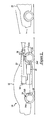
- FIGURE 1 is an emergency brake assist system in accordance with one embodiment of the present invention;
- FIGURE 2 is an emergency brake assist apparatus in accordance with one embodiment of the present invention; and
- FIGURE 3 depicts a flow chart of a method for providing emergency brake assistance in accordance with one embodiment of the present invention.
-
- In the following figures, the same reference numerals will be used to identify identical components in the various views. The present invention is illustrated with respect to an emergency brake assist system, particularly suited for the automotive field. However, the present invention is applicable to various other uses that may require an emergency brake assist system.
- Referring to FIGURE 1, an emergency
brake assist system 10 according to one embodiment of the present invention will be described. Avehicle 11 is provided withbrake mechanisms rear wheels - In one aspect of the invention,
brake mechanisms disc rotors wheels calipers 12b and 14b for braking the rotation ofdisc rotors - Further,
vehicle 11 comprises aforward detection apparatus 20 for detecting the distance between thedriving vehicle 11 and the vehicle ahead 22 by irradiating laser beams and the like.Vehicle 11 also includes an emergencybrake assist apparatus 23 having acontroller 24 receiving signals from theforward detection apparatus 20 and abraking system 26 for stoppingvehicle 11. - The intention of the present invention is to mitigate or avoid imminent frontal contact by means of amplifying brake application. Interventions should only occur when the opportunity to steer away from the threat is passed. The algorithm to realize the present invention is based on estimation of probability of collision and is effective against moving as well as stationary objects. Preliminary efficiency estimations show that contact with low relative speed can be avoided; at higher relative speed, the contact speed may be significantly reduced.
- Referring to FIGURE 2, an emergency
brake assist apparatus 23 according to one embodiment of the present invention will be described. Abrake pedal 28, operated by the driver (not shown), exerts a pedal force upon avariable brake booster 30. Thebraking system 26 is coupled to thevariable brake booster 30 that produces a variable brake booster force causing thebraking system 26 to exert a braking force proportional to the pedal force. - When a
forward detection apparatus 20 detects an imminent contact, it notifies the driver of an imminent contact andsignals controller 24.Controller 24 increases the variable brake booster force such that thebraking system 26 exerts an amplified braking force proportional to the pedal force. Because the emergencybrake assist apparatus 23 amplifies driver braking force upon imminent contact indication, intervention will only be effective when the driver presses thebrake pedal 28, and braking action can also still be modulated by the driver. - Amplifying brake force means using a modified characteristic for brake force vs. pedal force. In one aspect of the present invention, the brake force gain could, for example, be increased by a factor of four during imminent contact status.
- In an alterative embodiment of the present invention,
apparatus 23 includes a driverpresent switch 32, apassenger present switch 34, adriver seatbelt switch 36, and apassenger seatbelt switch 38. - If the
driver seatbelt switch 36 indicates that the driver is unbuckled, thenapparatus 23 will not allow amplified braking force and will continue to operate as a prior art system. Likewise, if thepassenger present switch 34 and thepassenger seatbelt switch 38 indicate that a passenger is present and unbuckled, thenapparatus 23 will not allow amplified braking force and will continue to operate as a prior art system. - The present invention requires a brake booster that has the ability to vary the gain of the brake pedal characteristic. Typically, this is only possible with electro-hydraulic or electro-mechanical brake systems. A conventional brake system with an electronically controlled active booster (such as the MK25 manufactured by Continental-Teves AG & Co) does not offer similar functionality.
- In the latter case, the ability for the driver to control the deceleration continuously during active booster activation is lost. The reason is that pedal pressure cannot be measured accurately during booster activation. The automatic braking action must consequently be enabled/disabled by a so-called "release switch". This concept also implies that full braking power has to be applied during activation, because once the active booster is activated, the brake pedal pressure cannot be measured accurately any longer.
- Referring to FIGURE 3, a method for providing
emergency brake assistance 40 in accordance with one embodiment of the present invention is illustrated.Method 40 begins withstep 42 by detecting an imminent contact. Upon detection of an imminent contact the sequence proceeds to step 44 by notifying the driver of the imminent contact. This warning may include an audible signal or a visual signal, such as a telltale or head-up display. The sequence then proceeds to step 46, by increasing the variable brake booster force by a predetermined factor proportional to force applied to the brake pedal by the driver. Thebraking system 26 will then exert an amplified braking force proportional to the pedal force. - The
method 40 shown also includesadditional steps steps step 48, the driver seatbelt status is determined. If the driver seatbelt is buckled, then the sequence proceeds to step 46 where amplified braking force is enabled. If the driver seatbelt is not buckled, then the sequence ends and amplified braking force is disabled. Instep 50, the presence of a passenger may be reduced. If a passenger is not present, then the sequence proceeds to step 46 where amplified braking force is enabled. If a passenger is present, then the sequence proceeds to step 52. Instep 52, the passenger seatbelt status is determined. If the passenger seatbelt is buckled, then the sequence proceeds to step 46 where amplified braking force is enabled. If the passenger seatbelt is not buckled, then the sequence ends and amplified braking force is disabled. - The method and apparatus of the present invention reduces crash energy in frontal collisions by enhancing driver performance during imminent contact situations. Additionally, the present invention does not cause the passengers to be more susceptible to airbag related injuries.
- Therefore in summary an emergency brake assist apparatus is disclosed which amplifies driver braking force upon imminent contact detection. A brake pedal, operated by the driver, exerts a pedal force upon a variable brake booster. A braking system is coupled to the variable brake booster that produces a variable brake booster force causing the braking system to exert a braking force proportional to the pedal force during normal operation. When a forward detection apparatus detects an imminent contact, a controller signals the variable brake booster to increase the variable brake booster force such that the braking system exerts an amplified braking force proportional to the pedal force.
- The present invention thus achieves an improved emergency brake assist apparatus. The present invention is advantageous in that it enhances driver braking performance during imminent contact situations. Additionally, the present invention maintains prior art braking levels when an occupant is unbelted.
- It is to be understood that the preceding description of the preferred embodiment is merely illustrative of some of the many specific embodiments that represent applications of the principles of the present invention. The person skilled in the art will appreciate that numerous other arrangements or constructions could be used without departing from the scope of the invention.
Claims (10)
- An emergency brake assist apparatus (23) having a brake pedal (28) coupled to a variable brake booster (30) for exerting a pedal force upon said variable brake booster (30) and a braking system (26) coupled to said variable brake booster (30) to produce a variable brake booster force and arranged to exert a braking force proportional to said pedal force during normal operation characterised in that the emergency brake assist apparatus (23) further comprises a forward detection apparatus (20) having control logic operative to detect an imminent contact and generate an imminent contact signal and a controller (24) coupled to said variable brake booster (30) and said forward collision detection apparatus (20) and having control logic operative to increase said variable brake booster force in response to said imminent contact signal so that said braking system exerts an amplified braking force proportional to said pedal force.
- An apparatus as claimed in claim 1 in which the forward detection apparatus (20) has control logic operative to detect an imminent contact and generate an imminent contact signal and notify a driver of said imminent contact.
- An apparatus as claimed in claim 2 wherein said forward detection apparatus (20) includes a forward contact warning apparatus to notify the driver of said imminent contact.
- An apparatus as claimed in any of claims 1 to 3 wherein said variable brake booster (30) comprises one of an electro-hydraulic brake booster and an electro-mechanical brake booster.
- An apparatus as claimed in any of claims 1 to 4 wherein the apparatus (23) further comprises a driver seatbelt switch (36) coupled to said controller (24) and operative to generate a driver unbuckled signal when a driver seatbelt is unbuckled.
- An apparatus as claimed in claim 5 wherein said controller (24) includes control logic operative to reduce said amplified braking force when said driver seatbelt is sensed to be unbuckled.
- An apparatus as claimed in any of claims 1 to 6 wherein the apparatus (23) further comprises at least one of a driver present switch (32) coupled to said controller (24) and operative to generate a driver present signal when a driver is sensed to be present in a driver seat and a passenger present switch (34) coupled to said controller (24) and operative to generate a passenger present signal when a passenger is sensed to be present in a passenger seat.
- An apparatus as claimed in any of claims 1 to 7 wherein the apparatus (23) further comprises a passenger seatbelt switch (38) coupled to said controller (24) and operative to generate a passenger unbuckled signal when a passenger seatbelt is sensed to be unbuckled.
- An apparatus as claimed in claim 8 when dependent upon claim 7 wherein said controller (24) includes control logic operative to reduce said amplified braking force when said passenger is sensed to be present and said passenger seatbelt is sensed to be unbuckled.
- A method (40) for providing emergency brake assistance characterised in that the method (40) comprises exerting a pedal force upon a variable brake booster (30), generating a variable brake booster force in which a braking system exerts a braking force proportional to said pedal force during normal operation, detecting an imminent contact, notifying a driver of said imminent contact and increasing said variable brake booster force so that said braking system exerts an amplified braking force proportional to said pedal force.
Applications Claiming Priority (2)
| Application Number | Priority Date | Filing Date | Title |
|---|---|---|---|
| US683007 | 1991-04-10 | ||
| US09/683,007 US6659572B2 (en) | 2001-11-08 | 2001-11-08 | System for exerting an amplified braking force |
Publications (1)
| Publication Number | Publication Date |
|---|---|
| EP1310413A1 true EP1310413A1 (en) | 2003-05-14 |
Family
ID=24742173
Family Applications (1)
| Application Number | Title | Priority Date | Filing Date |
|---|---|---|---|
| EP02102499A Withdrawn EP1310413A1 (en) | 2001-11-08 | 2002-10-27 | An Emergency Brake Assist Apparatus |
Country Status (2)
| Country | Link |
|---|---|
| US (1) | US6659572B2 (en) |
| EP (1) | EP1310413A1 (en) |
Families Citing this family (11)
| Publication number | Priority date | Publication date | Assignee | Title |
|---|---|---|---|---|
| WO2000027680A1 (en) * | 1998-11-11 | 2000-05-18 | Volkswagen Aktiengesellschaft | Method and device for controlling a brake system of a vehicle |
| DE10307463A1 (en) * | 2003-02-21 | 2004-09-02 | Robert Bosch Gmbh | Device for detecting an obstacle course |
| US7034668B2 (en) * | 2003-10-27 | 2006-04-25 | Ford Global Technologies, Llc | Threat level identification and quantifying system |
| DE102004062496A1 (en) * | 2004-12-24 | 2006-07-06 | Daimlerchrysler Ag | A method of operating a collision avoidance or collision sequence mitigation system of a vehicle and collision avoidance or collision mitigation system |
| US8046146B2 (en) * | 2006-02-03 | 2011-10-25 | Kelsey-Hayes Company | Adaptive ABS control |
| US7866427B2 (en) * | 2008-07-08 | 2011-01-11 | GM Global Technology Operations LLC | Vehicle multi-stage integrated brake assist for a collision preparation system |
| NZ591383A (en) * | 2008-09-04 | 2013-08-30 | Allflex Usa Inc | Combination full-duplex and half-duplex electronic identification tag |
| US20110168504A1 (en) * | 2010-01-14 | 2011-07-14 | Ksr Technologies Co. | Emergency braking system |
| US10737665B2 (en) | 2012-08-28 | 2020-08-11 | Ford Global Technologies, Llc | Vehicle braking based on external object communications |
| US10065618B2 (en) | 2013-04-12 | 2018-09-04 | Ford Global Technologies, Llc | Vehicle braking system and method |
| KR20200031808A (en) * | 2018-09-17 | 2020-03-25 | 현대자동차주식회사 | Control system and method for preventing sudden acceleration of vehicle |
Citations (3)
| Publication number | Priority date | Publication date | Assignee | Title |
|---|---|---|---|---|
| US5278764A (en) * | 1990-01-29 | 1994-01-11 | Nissan Motor Company, Limited | Automatic braking system with proximity detection to a preceding vehicle |
| DE19817326A1 (en) * | 1998-04-18 | 1999-10-21 | Continental Teves Ag & Co Ohg | Method of reducing braking distance to enable suitable deceleration in all driving situations |
| EP0976627A1 (en) * | 1998-02-18 | 2000-02-02 | Honda Giken Kogyo Kabushiki Kaisha | Brake controller of vehicle |
Family Cites Families (21)
| Publication number | Priority date | Publication date | Assignee | Title |
|---|---|---|---|---|
| JPS5269132A (en) | 1975-12-08 | 1977-06-08 | Nissan Motor Co Ltd | Collision preventing apparatus |
| US4146108A (en) | 1976-01-02 | 1979-03-27 | Yasuo Sato | Braking system responsive to abrupt release of accelerator pedal |
| JP3197307B2 (en) | 1991-10-14 | 2001-08-13 | マツダ株式会社 | Travel control device for mobile vehicles |
| JPH05278581A (en) | 1992-03-30 | 1993-10-26 | Mazda Motor Corp | Vehicle automatic braking device |
| JP3128176B2 (en) | 1993-05-24 | 2001-01-29 | マツダ株式会社 | Vehicle obstacle detection device |
| CN1043464C (en) | 1993-12-27 | 1999-05-26 | 现代电子产业株式会社 | Apparatus for and method of preventing car collision utilizing laser |
| JP2925461B2 (en) | 1994-09-27 | 1999-07-28 | 日産ディーゼル工業株式会社 | Rear-end collision prevention device for vehicles |
| JP2869888B2 (en) | 1995-11-21 | 1999-03-10 | 本田技研工業株式会社 | Vehicle collision prevention device |
| US5941608A (en) | 1996-03-07 | 1999-08-24 | Kelsey-Hayes Company | Electronic brake management system with manual fail safe |
| JP3528419B2 (en) | 1996-04-26 | 2004-05-17 | トヨタ自動車株式会社 | Braking force control device |
| DE19629229C2 (en) | 1996-07-20 | 2002-06-20 | Daimler Chrysler Ag | Procedure for performing an automatic braking process |
| JPH10109627A (en) | 1996-10-04 | 1998-04-28 | Denso Corp | Automatic deceleration control method, automatic deceleration control device, inter-vehicle distance control method, inter-vehicle distance control device, and storage medium |
| EP0891903B1 (en) | 1997-07-17 | 2009-02-11 | Volkswagen Aktiengesellschaft | Automatic emergency brake function |
| JPH1148952A (en) | 1997-08-06 | 1999-02-23 | Mitsubishi Electric Corp | Vehicle braking system |
| DE19753971B4 (en) | 1997-12-05 | 2009-11-26 | Robert Bosch Gmbh | Method and device for controlling a brake system of a vehicle |
| JP4011711B2 (en) * | 1998-01-13 | 2007-11-21 | 本田技研工業株式会社 | Vehicle travel safety device |
| JPH11321598A (en) * | 1998-05-07 | 1999-11-24 | Honda Motor Co Ltd | Vehicle driving safety device |
| JP3853991B2 (en) * | 1998-11-04 | 2006-12-06 | 本田技研工業株式会社 | Vehicle travel safety device |
| DE19900314C2 (en) | 1999-01-07 | 2000-10-19 | Daimler Chrysler Ag | Method and device for braking a motor vehicle in the vicinity with an obstacle |
| JP3676616B2 (en) * | 1999-04-28 | 2005-07-27 | 本田技研工業株式会社 | Obstacle detection device |
| DE60023077T2 (en) * | 1999-09-06 | 2006-07-13 | Nissan Motor Co., Ltd., Yokohama | Method and device for supporting the braking operation of a driver |
-
2001
- 2001-11-08 US US09/683,007 patent/US6659572B2/en not_active Expired - Lifetime
-
2002
- 2002-10-27 EP EP02102499A patent/EP1310413A1/en not_active Withdrawn
Patent Citations (3)
| Publication number | Priority date | Publication date | Assignee | Title |
|---|---|---|---|---|
| US5278764A (en) * | 1990-01-29 | 1994-01-11 | Nissan Motor Company, Limited | Automatic braking system with proximity detection to a preceding vehicle |
| EP0976627A1 (en) * | 1998-02-18 | 2000-02-02 | Honda Giken Kogyo Kabushiki Kaisha | Brake controller of vehicle |
| DE19817326A1 (en) * | 1998-04-18 | 1999-10-21 | Continental Teves Ag & Co Ohg | Method of reducing braking distance to enable suitable deceleration in all driving situations |
Also Published As
| Publication number | Publication date |
|---|---|
| US20030085617A1 (en) | 2003-05-08 |
| US6659572B2 (en) | 2003-12-09 |
Similar Documents
| Publication | Publication Date | Title |
|---|---|---|
| US6523912B1 (en) | Autonomous emergency braking system | |
| US6517172B1 (en) | Driver augmented autonomous braking system | |
| JP3025261B2 (en) | Method and apparatus for generating operation signal of stop lamp for automobile | |
| US8556353B2 (en) | Brake device | |
| US9156354B2 (en) | Driver assistance system having autonomous braking to a standstill | |
| US6655749B2 (en) | Accelerator actuated emergency braking system | |
| US6342832B1 (en) | Preventing the collision of a vehicle with an obstacle | |
| CN107444372B (en) | Method for operating a vehicle brake assistance system | |
| CN103079916A (en) | Method for protecting a vehicle with an automatic parking brake | |
| US6160476A (en) | Method and system for providing an optical signal at the rear of a vehicle to warn the driver of a following vehicle | |
| US6659572B2 (en) | System for exerting an amplified braking force | |
| JP3209406B2 (en) | Driving support device for vehicles | |
| JP2012006423A (en) | Emergency brake mechanism | |
| JPH07117644A (en) | Vehicle braking system | |
| US6559762B1 (en) | Multi channel braking notification system | |
| EP3645351B1 (en) | Method for actuating a parking brake system and parking brake system | |
| US7142965B2 (en) | Method for obtaining triggering signals for passive safety devices of a motor vehicle from data of a vehicle dynamics control system | |
| US12172618B2 (en) | Braking control apparatus | |
| US20030122420A1 (en) | Brake pedal system for improved braking performance | |
| JPH04123757U (en) | Vehicle automatic braking system | |
| JP2001515819A (en) | Apparatus and method for driving vehicle brake system | |
| JP3134559B2 (en) | Vehicle control device | |
| JPH05270372A (en) | Vehicle control device | |
| KR100224398B1 (en) | Brake system of a car | |
| KR20130054033A (en) | A speed reducing control method and system on split surface road wherein vehicle which having abs |
Legal Events
| Date | Code | Title | Description |
|---|---|---|---|
| PUAI | Public reference made under article 153(3) epc to a published international application that has entered the european phase |
Free format text: ORIGINAL CODE: 0009012 |
|
| AK | Designated contracting states |
Designated state(s): AT BE BG CH CY CZ DE DK EE ES FI FR GB GR IE IT LI LU MC NL PT SE SK TR |
|
| AX | Request for extension of the european patent |
Extension state: AL LT LV MK RO SI |
|
| 17P | Request for examination filed |
Effective date: 20031106 |
|
| AKX | Designation fees paid |
Designated state(s): DE FR GB |
|
| 17Q | First examination report despatched |
Effective date: 20060907 |
|
| STAA | Information on the status of an ep patent application or granted ep patent |
Free format text: STATUS: THE APPLICATION IS DEEMED TO BE WITHDRAWN |
|
| RIN1 | Information on inventor provided before grant (corrected) |
Inventor name: TARABISHY, M., NABEEL Inventor name: TELLIS, LEVASSEUR Inventor name: EKMARK, JONAS Inventor name: JANSSON, JONAS, LARS, ZAKARIAS Inventor name: ENGELMAN, GERALD, H. Inventor name: BOND, JOHN, VINCENT III |
|
| 18D | Application deemed to be withdrawn |
Effective date: 20070320 |