EP1310324A1 - Machine tool and its pallet changing device - Google Patents
Machine tool and its pallet changing device Download PDFInfo
- Publication number
- EP1310324A1 EP1310324A1 EP01956827A EP01956827A EP1310324A1 EP 1310324 A1 EP1310324 A1 EP 1310324A1 EP 01956827 A EP01956827 A EP 01956827A EP 01956827 A EP01956827 A EP 01956827A EP 1310324 A1 EP1310324 A1 EP 1310324A1
- Authority
- EP
- European Patent Office
- Prior art keywords
- pallet
- pair
- support body
- workpiece
- loading station
- Prior art date
- Legal status (The legal status is an assumption and is not a legal conclusion. Google has not performed a legal analysis and makes no representation as to the accuracy of the status listed.)
- Granted
Links
Images



Classifications
-
- B—PERFORMING OPERATIONS; TRANSPORTING
- B23—MACHINE TOOLS; METAL-WORKING NOT OTHERWISE PROVIDED FOR
- B23Q—DETAILS, COMPONENTS, OR ACCESSORIES FOR MACHINE TOOLS, e.g. ARRANGEMENTS FOR COPYING OR CONTROLLING; MACHINE TOOLS IN GENERAL CHARACTERISED BY THE CONSTRUCTION OF PARTICULAR DETAILS OR COMPONENTS; COMBINATIONS OR ASSOCIATIONS OF METAL-WORKING MACHINES, NOT DIRECTED TO A PARTICULAR RESULT
- B23Q7/00—Arrangements for handling work specially combined with or arranged in, or specially adapted for use in connection with, machine tools, e.g. for conveying, loading, positioning, discharging, sorting
- B23Q7/14—Arrangements for handling work specially combined with or arranged in, or specially adapted for use in connection with, machine tools, e.g. for conveying, loading, positioning, discharging, sorting co-ordinated in production lines
- B23Q7/1426—Arrangements for handling work specially combined with or arranged in, or specially adapted for use in connection with, machine tools, e.g. for conveying, loading, positioning, discharging, sorting co-ordinated in production lines with work holders not rigidly fixed to the transport devices
- B23Q7/1431—Work holder changers
-
- Y—GENERAL TAGGING OF NEW TECHNOLOGICAL DEVELOPMENTS; GENERAL TAGGING OF CROSS-SECTIONAL TECHNOLOGIES SPANNING OVER SEVERAL SECTIONS OF THE IPC; TECHNICAL SUBJECTS COVERED BY FORMER USPC CROSS-REFERENCE ART COLLECTIONS [XRACs] AND DIGESTS
- Y10—TECHNICAL SUBJECTS COVERED BY FORMER USPC
- Y10T—TECHNICAL SUBJECTS COVERED BY FORMER US CLASSIFICATION
- Y10T29/00—Metal working
- Y10T29/51—Plural diverse manufacturing apparatus including means for metal shaping or assembling
- Y10T29/5196—Multiple station with conveyor
-
- Y—GENERAL TAGGING OF NEW TECHNOLOGICAL DEVELOPMENTS; GENERAL TAGGING OF CROSS-SECTIONAL TECHNOLOGIES SPANNING OVER SEVERAL SECTIONS OF THE IPC; TECHNICAL SUBJECTS COVERED BY FORMER USPC CROSS-REFERENCE ART COLLECTIONS [XRACs] AND DIGESTS
- Y10—TECHNICAL SUBJECTS COVERED BY FORMER USPC
- Y10T—TECHNICAL SUBJECTS COVERED BY FORMER US CLASSIFICATION
- Y10T409/00—Gear cutting, milling, or planing
- Y10T409/30—Milling
- Y10T409/304536—Milling including means to infeed work to cutter
- Y10T409/30532—Milling including means to infeed work to cutter with means to advance work or product
-
- Y—GENERAL TAGGING OF NEW TECHNOLOGICAL DEVELOPMENTS; GENERAL TAGGING OF CROSS-SECTIONAL TECHNOLOGIES SPANNING OVER SEVERAL SECTIONS OF THE IPC; TECHNICAL SUBJECTS COVERED BY FORMER USPC CROSS-REFERENCE ART COLLECTIONS [XRACs] AND DIGESTS
- Y10—TECHNICAL SUBJECTS COVERED BY FORMER USPC
- Y10T—TECHNICAL SUBJECTS COVERED BY FORMER US CLASSIFICATION
- Y10T409/00—Gear cutting, milling, or planing
- Y10T409/30—Milling
- Y10T409/30868—Work support
- Y10T409/308792—Indexable
Definitions
- the present invention relates to a machine tool for machining a workpiece by moving a tool and the workpiece relative to each other and to a pallet changer thereof, and particularly to a machine tool such as a machining center having a pallet changer attached thereto for changing pallets having a workpiece mounted thereon between a table and a pallet stocker, i.e. a pallet loading station and to a pallet changer thereof.
- a machine tool such as a machining center is provided with a pallet changer, by which a pallet having a machined workpiece mounted thereon and placed on the table of the machine tool is exchanged with a pallet having a set-up workpiece mounted thereon and placed on a pallet loading station.
- a pallet changer is disclosed, for example, in Japanese Unexamined Utility Model Publication No. 2-53335.
- This pallet changer comprises pallet change arms which are adapted to be able to swivel about a vertical axis and to move up and down (in a vertical direction).
- the pallet changer for a machine tool disclosed in Japanese Unexamined Utility Model Publication No. 2-53335 is configured of a frame structure including a beam arranged above the pallet change arms, an arm shaft fixed to the pallet change arms and supported vertically movably and swingably by the beam of the frame structure, and actuators arranged on the beam for vertically moving the arm shaft and swiveling it.
- the pallets are released from each of the table and the pallet loading station, and the pallet change arms are then moved up through the arm shaft by a first actuator, thereby to lift up the pallets on the table and on the pallet loading station to an upper pallet changing position.
- the pallet change arms are swiveled through the arm shaft by a second actuator, so that the pallet on the side of the table (i.e. the machining position) is replaced with the pallet on the side of the pallet loading station (i.e. the standby position).
- the pallet change arms are moved down to a lower pallet mounting position through the arm shaft by the first actuator, and the pallets are placed and fixed on the table and the pallet loading station, respectively.
- the pallet change arms on the sides of both the table and the pallet loading station can be moved down only to the same vertical position along with each other.
- the vertical position of the pallet on the side of the pallet loading station is set to the same vertical position as the pallet mounting position on the table.
- the set-up process is conducted, on the side of the pallet loading station, for mounting on a pallet a next workpiece to be machined and removing the machined workpiece from the pallet, etc.
- the pallet change arms on the sides of the table and the pallet loading station can be moved down only to the same vertical position. Especially in a large-size machine tool such a machining center, this results in the very high vertical position for the pallet loading station, and therefore a stool or the like is required for the set-up job, thereby posing the problem of a deteriorated working environment and safety.
- an object of the present invention is to provide a machine tool, and a pallet changer therefor, in which the vertical position of the working surface for the pallet loading station can be set to a lower level than the upper surface of the machine tool table in carrying out the set-up job for changing the pallets between the pallet loading station for set-up job and the table.
- Another object of the invention is to provide a machine tool, and a pallet changer therefor, in which the vertical position of the pallet change arm on the side of the pallet loading station can be freely set independently of the vertical position of the upper surface of the table.
- a machine tool for machining a workpiece by moving a tool and the workpiece in relation to each other which includes a spindle for mounting the tool thereon, a table for a pallet having the workpiece mounted thereon to be placed on the table, a pallet loading station for conducting the set-up job thereon including the mounting/demounting of the workpiece on/from the pallet, and a pallet changer including a pair of pallet change arms, each pallet change arm having a pallet holder for holding selected one of a pallet on the table and a pallet on the pallet loading station, the pair of the pallet change arms being swiveled about a vertical axis thereby to exchange the pallets between the table and the pallet loading station, the pair of the pallet change arms arranged to be able move independently of each other in the vertical direction.
- a machine tool for machining a workpiece by moving a tool and the workpiece in relation to each other which includes a spindle for mounting the tool thereon, a table for a pallet having the workpiece mounted thereon to be placed on the table, a pallet loading station for conducting the set-up job including the mounting/demounting of the workpiece on/from the pallet, and a pallet changer including a support body interposed between the table and the pallet loading station and able to swivel about a vertical axis, and a pair of pallet change arms mounted on the support body and extending horizontally in opposite directions from the support body, the support body being swiveled thereby to move one of the pallet change arms from the side of the table to the side of the pallet loading station and the other pallet change arm from the side of the pallet load station to the side of the table, the pair of the pallet change arms being able to move independently of each other, in the vertical direction, on the support body.
- a machine tool for machining a workpiece by moving a tool and the workpiece in relation to each other which includes a spindle for mounting the tool mounted thereon, a table for a pallet having the workpiece mounted thereon to be placed on the table, a pallet loading station for conducting the set-up job thereon including the mounting/demounting of the workpiece on/from the pallet, a base disposed between the table and the pallet loading station, a support body able to swivel in relation to the base about a vertical axis, swiveling means disposed on the base for swiveling the support body, a pair of pallet change arms, each pallet change arm including a pallet holder for holding a pallet on the table or a pallet on the pallet loading station, the pair of the pallet change arms arranged to swivel integrally with the support body by the swiveling means and to be able to move independently of each other in the vertical direction on the support body and first vertical driving
- a machine tool for machining a workpiece by moving a tool and the workpiece in relation to each other which includes a spindle for mounting the tool mounted thereon, a table for a pallet having the workpiece mounted thereon to be placed on the table, a pallet loading station for conducting the set-up job including the mounting/demounting of the workpiece on/from the pallet, a base disposed between the table and the pallet loading station, a support body able to swivel in relation to the base about a vertical axis, swiveling means disposed on the base for swiveling the support body, a pair of pallet change arms, each pallet change arm including a pallet holder for holding a pallet on the table or a pallet on the pallet loading station, the pair of the pallet change arms arranged to swivel integrally with the support body by the swiveling means and to be able to move independently of each other in the vertical direction on the support body, first vertical driving means
- a pallet changer which includes a support body able to swivel about a vertical axis and a pair of pallet change arms extending horizontally in opposite directions from the support body, the support body being swiveled thereby to move one of the pair of the pallet change arms from a machining position to a standby position and the other pallet change arm from the standby position to the machining position, wherein the pair of the pallet change arms are arranged to able to move independently of each other in the vertical direction on the support body.
- one of the pair of the pallet change arms can further move downward after the other pallet change arm stops. More preferably, the pair of the pallet change arms are moved in the vertical direction by a single operating rod driven by two cylinder units connected in series to each other, so that the pair of the pallet change arms can assume three different vertical positions, and that a stopper restricts the downward movement of one of the pair of the pallet change arms. Further, each of the pair of the pallet change arms may be moved in the vertical direction by a different operating rod driven by a different cylinder unit.
- the standby position (on the side of the pallet loading station) usable for the setup job, etc. can be set lower than the pallet in the machining position (on the side of the table) facing the machine tool.
- a pair of pallet change arms are movable independently of each other in the vertical direction, and therefore the vertical position of the pallet change arm on the side of the pallet loading station can be set to a level lower than the vertical position of the pallet change arm on the side of the table of the machine tool.
- the working surface of the pallet loading station can be set low, thereby improving the efficiency and safety of the set-up job.
- Fig. 1 is a perspective view showing a pallet changer of a machine tool according to the present invention.
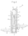
- Fig. 2 is a partial sectional side view showing the internal structure of the pallet changer of the machine tool shown in Fig. 1.
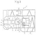
- Fig. 3 is a plan view of a machine tool provided with the pallet changer shown in Figs. 1 and 2.
- Fig. 4A is a schematic diagram showing the operation of a pallet changer of a machine tool according to the present invention, when mounting a pallet on the table of the machine tool.
- Fig. 4B is a schematic diagram showing the operation of the pallet changer for the machine tool according to the present invention, when exchanging the pallet on the side of the table with the pallet on the side of the pallet loading station.
- Fig. 4C is a schematic diagram showing the operation of the pallet changer for the machine tool according to the present invention, when mounting the pallet on the pallet loading station.
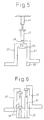
- Fig. 5 is a schematic diagram showing a pallet changer for a machine tool according to another embodiment of the present invention.
- Fig. 6 is a schematic diagram showing a pallet changer for a machine tool according to still another embodiment of the present invention.
- a machine tool 11 includes a bed 13, a column 15, a spindle head 17 mounted on the column 15, a spindle 19, a table 21 and a pallet loading station 23 for changing a pallet.
- a pallet changer 25 is disposed between the table 21 and the pallet loading station 23 of the machine tool 11.
- the spindle 19 is arranged horizontally, and the spindle head 17 is mounted to be able to move in the vertical direction (in a direction of a Y-axis) on the column by a well-known slide guide mechanism.
- the column 15 is movable in the lateral direction (in a direction of an X-axis) on the bed 13, as viewed from the front of the machine tool 11, while the table 21 is movable in the backward and forward direction (in a direction of a Z-axis) on the bed 13.
- the spindle 19 is movable in relation to the table 21 in the three directions along the X-, Y- and Z-axes.
- a tool magazine 27 for an automatic tool changer is disposed on the left side of the spindle 19, and a NC unit 29 is disposed on the right side of the spindle 19.
- the pallet P can be accurately supported in position simply by placing it on the table 21.
- the table 21 is movable in the backward and forward direction (along the Z-axis), and therefore is adapted to be movable in relation to the spindle 19 for the machining operation, thereby allowing the table 21 to move to the position of the pallet P indicated by chain line at the time of changing the pallet.
- the pallet changer 25 includes a base 31 arranged on the bed 13 of the machine tool 11, an arm base, i.e. a support body 35 extending vertically from the base 31 and able to swivel about the vertical axis 33, and a pair of pallet change arms 37 extending horizontally in opposite directions from the support body 35.
- the two pallet change arms 37 is arranged at a position nearer to the machine tool 11 called “the machining position”
- the other pallet change arm 37 is arranged at a position nearer to the pallet loading station 23 called "the standby position”.
- Each of pallet change arms 37 includes a slide plate 37a movable in the vertical direction on the support body 35 along a pair of guides 39 located on the support body 35, and a forked pallet holder 37b extending in the horizontal direction from the slide plate 37a, with the forward end thereof branching into two parts.
- the pallet change arm 37 is mounted movably on the support body 35 by the slide plate 37a.
- the upper portion of the slide plate 37a further includes a projected portion 37c projecting from the slide plate 37a and extending in the horizontal direction.
- the vertical driving means includes a first cylinder unit (i.e. first vertical driving means) 41 mounted on the base 31 and extensible in the vertical direction, and a second cylinder unit (i.e. second vertical driving means) 47 connected in series with the first cylinder unit 41 though the operating end portion 45 of the operating rod 43 of the first cylinder unit 41 and extensible in the vertical direction.
- the operating end portion 51 of the operating rod 49 of the second cylinder unit 47 and the projected portion 37c of the pallet change arm 37 come into contact with each other, so that the driving force of the vertical driving means is transmitted to the pallet change arm 37, and the pallet change arm 37 moves vertically on the support body 35 along the guides 39.
- the support body 35 is further coupled to the operating end portion 45 of the first cylinder unit 41, so that, in accordance with the extension or contraction of the first cylinder unit 41 in the vertical direction, the support body 35 is moved in the vertical direction together with the second cylinder unit 47.
- the support body 35 can swivel in relation to the base 31 about the vertical axis 33 by the swiveling force applied thereto from the swiveling means.
- the swiveling means may be configured of, for example, a rack-pinion mechanism as shown in Fig. 2.
- the pinion 53 of the swiveling means is of a cylindrical shape with the vertical axis 33 as a rotational axis, and arranged as to surround the first cylinder unit 41.
- the first cylinder unit 41 surrounded by the cylindrical pinion 53 is shown by dotted line to facilitate the description.
- One end of the cylindrical pinion 53 is further connected fixedly to the bottom portion of the support body 35.
- the rack 55 in mesh with the pinion 53 is driven in the horizontal direction by an appropriate driving unit (not shown), so that the support body 35 swivels about the vertical axis 33, thereby causing the pair of pallet change arms 37 to swivel about the vertical axis 33.
- the support body 35 to which the pinion 53 is connected is coupled with the first cylinder unit 41.
- the support body 35 moves in relation to the base 31 in the vertical direction, so that the pinion 53 connected to the support body 35 also moves in relation to the base 31 in the vertical direction.
- the rack 55 arranged on the base 31 may be kept in engagement with the pinion 53 even when the pinion 53 moves in relation to the base 31 in the vertical direction, the pinion 53 is elongated along the vertical direction.
- FIG. 2 employs the rack-pinion mechanism for swiveling the support body 35, other appropriate swiveling mechanisms can of course be used alternatively.
- the two cylinder units 41, 47 are connected in series with each other, so that the pair of the pallet change arms 37 can be driven in the vertical direction by one operating rod 49 driven by the cylinder units 41, 47. This allows the pallet change arms 37 to assume three different positions (heights) in the vertical direction.
- a stopper 57 is disposed on one side of the base 31 in order to restrict the movement (i.e. downward movement) of one (normally, the pallet change arm 37 in standby position) of the pair of the pallet change arms 37 during the downward movement of the pair of the pallet change arms 37.
- the two pallet change arms 37 of the pallet changer 25 of the machine tool 11 stand by at the vertical position shown in Fig. 4A (where the pallet is placed and mounted on the table 21, hereinafter referred to as the table mounting position).
- the table 21 moves toward the pallet changer 25, so that the pallet P having the machined workpiece mounted thereon is transferred to the pallet change arm 37 of the pallet changer 25.
- the first cylinder unit 41 extends to move the two pallet change arms 37 up to the vertical position shown in Fig. 4B (hereinafter referred to as the pallet changing position).
- the base 31 ceases to prevent the swivel of the support body 35 and the pallet change arms 37.
- the support body 35 is swiveled by the rack-and-pinion mechanism, so that one pallet change arm 37 is swiveled from the machining position to the standby position while the other pallet change arm 37 is swiveled from the standby position to the machining position.
- the first cylinder unit 41 is contracted thereby to move the two pallet change arms 37 down to a vertical position where the pallet change arm 37 in the machining position (i.e. on the side of the machine tool) comes into contact with the stopper 57.
- the two pallet change arms 37 will assume the table mounting position, and the pallet P held by the pallet change arm 37 in the machining position will be mounted on the table 21 of the machine tool 11.
- the second cylinder unit 47 is contracted to move the other pallet change arm 37 down to the vertical position shown in Fig. 4C (where the pallet is placed and mounted on the pallet loading station, hereinafter referred to as the pallet loading station mounting position).
- the pallet change arm 37 in the machining position is stopped by the stopper 57, and therefore cannot move down below the table mounting position.
- the pallet change arm 37 in the standby position moves down to the pallet loading station mounting position, with the result that the pallet P held in the pallet change arm 37 in the standby position is mounted on the pallet loading station 23.
- the pair of the pallet change arms 37 can be moved in the vertical direction independently of each other on the support body 35 to assume different vertical positions respectively.
- the vertical position of the pallet P in the standby position can be set lower than that of the pallet P in the machining position, so that the set-up job on the pallet loading station 23 is facilitated for an improved efficiency and safety of the set-up job.
- the second cylinder unit 47 When the set-up job for the workpiece is completed on the pallet loading station 23, on the side of which the pallet change arm 37 in the standby position is arranged, the second cylinder unit 47 is extended to move the pallet change arm 37 up to the table mounting position, as shown in Fig. 4A. Under the condition shown in Fig. 4C, only the projected portion 37c of the pallet change arm 37 in the standby position is in contact with the operating end portion 51 of the operating rod 49, and therefore only the pallet change arm 37 in the standby position moves up.
- the pallet changer 25 of the machine tool 11 is described above with reference to an embodiment in which the pallet change arms 37 are moved in the vertical direction by the vertical driving means including the first and second cylinder units 41, 47 connected in series to each other, it is not limited to the embodiment described above. Also, since the scope of the present invention is defined by the appended claims, any modifications and changes can be made without departing from the scope of the same claims.
- the first and second cylinder units 41, 47 connected in series to each other may be suspended from the ceiling thereby to move the two pallet change arms 37 with a single operating rod 49 driven by the first and second cylinder units 41, 47 connected in series to each other.
- the stopper 57 is required for restricting the downward movement of only one pallet change arm 37.
- each of the two pallet change arms 37 may be driven by an independent vertical driving means.
- one of the pallet change arms 37 is driven by the two cylinder units 59 connected in series to each other, while the other pallet change arm 37 is driven by one cylinder unit 61. Therefore, the former pallet change arm 37 can take three different vertical positions, while the latter pallet change arm 37 can take two different vertical positions.
- the same operation as in the embodiment shown in Figs. 1 and 2 can be performed without any stopper.
- a single cylinder unit capable of taking three or more different positions can be employed in place of the first and second cylinder units 41, 47 connected in series to each other.
- the support body 35, etc. are omitted in Figs. 5 and 6 as in Figs. 4A to 4C for the purpose of simplification.
Landscapes
- Engineering & Computer Science (AREA)
- Mechanical Engineering (AREA)
- Feeding Of Workpieces (AREA)
Abstract
Description
Claims (8)
- A machine tool for machining a workpiece by moving a tool and the workpiece in relation to each other, said machine tool comprising:a spindle for mounting said tool thereon;a table for a pallet having said workpiece mounted thereon to be placed on said table;a pallet loading station for conducting the set-up job thereon including the mounting/demounting of said workpiece on/from said pallet; anda pallet changer including a pair of pallet change arms, each pallet change arm having a pallet holder for holding selected one of a pallet on said table and a pallet on said pallet loading station, said pair of the pallet change arms being swiveled about a vertical axis thereby to exchange the pallets between said table and said pallet loading station, said pair of the pallet change arms arranged to be able to move independently of each other in the vertical direction.
- A machine tool for machining a workpiece by moving a tool and the workpiece in relation to each other, said machine tool comprising:a spindle for mounting said tool thereon;a table for a pallet having said workpiece mounted thereon to be placed on said table;a pallet loading station for conducting the set-up job thereon including the mounting/demounting of said workpiece on/from said pallet; anda pallet changer including a support body interposed between said table and said pallet loading station and able to swivel about a vertical axis, and a pair of pallet change arms mounted on said support body and extending horizontally in opposite directions from said support body, said support body being swiveled thereby to move one of said pallet change arms from the side of said table to the side of said pallet loading station and the other pallet change arm from the side of said pallet load station to the side of said table, said pair of the pallet change arms being able to move independently of each other in the vertical direction on said support body.
- A machine tool for machining a workpiece by moving a tool and the workpiece in relation to each other, said machine tool comprising:a spindle for mounting said tool thereon;a table for a pallet having the workpiece mounted thereon to be placed on said table;a pallet loading station for conducting the set-up job thereon including the mounting/demounting of said workpiece on/from said pallet;a base disposed between said table and said pallet loading station;a support body able to swivel in relation to said base about a vertical axis;swiveling means disposed on said base for swiveling said support body;a pair of pallet change arms, each pallet change arm including a pallet holder for holding a pallet on said table or a pallet on said pallet loading station, said pair of the pallet change arms arranged to swivel integrally with said support body by said swiveling means to be able to move independently of each other in the vertical direction on said support body;first vertical driving means disposed on said support body for vertically moving one of said pair of the pallet change arms;second vertical driving means disposed on said support body in series with said first vertical driving means for vertically moving said pair of the pallet change arms in cooperation with said first vertical driving means; anda stopper for restricting the movement of one of the pair of pallet change arms on the side of said table, when said pair of the pallet change arms are moved downward by said second vertical driving means.
- A machine tool for machining a workpiece by moving a tool and the workpiece in relation to each other, comprising:a spindle for mounting said tool thereon;a table for a pallet having said workpiece mounted thereon to be placed on said table;a pallet loading station for conducting the set-up job including the mounting/demounting of said workpiece on/from said pallet;a base disposed between said table and said pallet loading station;a support body able to swivel in relation to said base about a vertical axis;swiveling means disposed on said base for swiveling said support body;a pair of pallet change arms, each pallet change arm including a pallet holder for holding a pallet on said table and a pallet on said pallet loading station, said pair of the pallet change arms arranged to swivel integrally with said support body by said swiveling means and to be able to move independently of each other in the vertical direction on said support body;first vertical driving means disposed on said support body for vertically moving one of said pair of the pallet change arms on the side of said pallet loading station;second vertical driving means disposed on said support body in series with said first vertical driving means for vertically moving said one of said pair of the pallet change arms on the side of said pallet loading station in cooperation with said first vertical drive means; andthird vertical driving means disposed on said support body in parallel to said first vertical driving means and said second vertical driving means for vertically moving the other of said pair of the pallet change arms on the side of said table.
- A pallet changer comprising a support body able to swivel about a vertical axis and a pair of pallet change arms extending horizontally in opposite directions from said support body, said support body being swiveled thereby to move one of said pair of the pallet change arms from a machining position to a standby position and the other pallet change arm from the standby position to the machining position;
wherein said pair of the pallet change arms are arranged to be able to move independently of each other in the vertical direction on said support body. - The pallet changer according to claim 5, wherein during the downward movement of said pair of the pallet change arms, one of said pair of the pallet change arms can further move downward after the other pallet change arm stops.
- The pallet changer according to claim 6, wherein said pair of the pallet change arms are moved in the vertical direction by a single operating rod driven by two cylinder units connected in series to each other, so that said pair of the pallet change arms can assume three different vertical positions, and wherein a stopper restricts the downward movement of one of said pair of the pallet change arms.
- The pallet changer according to claim 5, wherein each of said pair of the pallet change arms is moved in the vertical direction by a different operating rod driven by a different cylinder unit.
Applications Claiming Priority (3)
| Application Number | Priority Date | Filing Date | Title |
|---|---|---|---|
| JP2000245798 | 2000-08-14 | ||
| JP2000245798 | 2000-08-14 | ||
| PCT/JP2001/006880 WO2002014013A1 (en) | 2000-08-14 | 2001-08-09 | Machine tool and its pallet changing device |
Publications (3)
| Publication Number | Publication Date |
|---|---|
| EP1310324A1 true EP1310324A1 (en) | 2003-05-14 |
| EP1310324A4 EP1310324A4 (en) | 2004-03-17 |
| EP1310324B1 EP1310324B1 (en) | 2005-07-20 |
Family
ID=18736253
Family Applications (1)
| Application Number | Title | Priority Date | Filing Date |
|---|---|---|---|
| EP01956827A Expired - Lifetime EP1310324B1 (en) | 2000-08-14 | 2001-08-09 | Machine tool |
Country Status (5)
| Country | Link |
|---|---|
| US (1) | US6647605B2 (en) |
| EP (1) | EP1310324B1 (en) |
| JP (1) | JP3939247B2 (en) |
| DE (1) | DE60112098T2 (en) |
| WO (1) | WO2002014013A1 (en) |
Cited By (4)
| Publication number | Priority date | Publication date | Assignee | Title |
|---|---|---|---|---|
| ITTO20110599A1 (en) * | 2011-07-07 | 2013-01-08 | Comau Spa | STATION FOR LOADING AND UNLOADING OF BOXES |
| US11021200B2 (en) | 2014-12-15 | 2021-06-01 | Comau Llc | Modular vehicle assembly system and method |
| US11420853B2 (en) | 2019-10-03 | 2022-08-23 | Comau Llc | Assembly material logistics system and methods |
| US11905114B2 (en) | 2020-06-08 | 2024-02-20 | Comau Llc | Assembly material logistics system and methods |
Families Citing this family (16)
| Publication number | Priority date | Publication date | Assignee | Title |
|---|---|---|---|---|
| JP4340739B2 (en) * | 2002-11-13 | 2009-10-07 | 森精機興産株式会社 | Pallet changer for machine tool and machine tool |
| DE602005005615T2 (en) * | 2004-12-29 | 2009-04-30 | Doosan Infracore Co., Ltd. | Pallet changer for a machine tool |
| US20070010385A1 (en) * | 2005-07-05 | 2007-01-11 | Kao Fong Machinery Co., Ltd. | Exchange system of rotary worktables |
| DE102005043602B4 (en) * | 2005-09-12 | 2018-07-26 | Reishauer Ag | Gear processing machine and method for operating such a gear processing machine |
| US7147595B1 (en) * | 2005-12-13 | 2006-12-12 | Hsi-Kuan Chen | CNC machine tool |
| US7490710B1 (en) | 2006-08-19 | 2009-02-17 | Wes-Tech Automation Solutions, Llc | Flexible manufacturing system having modular work stations |
| JP5171111B2 (en) * | 2007-05-29 | 2013-03-27 | オークマ株式会社 | Pallet changer |
| US20090026683A1 (en) * | 2007-07-24 | 2009-01-29 | Jack Leon Bayer | Bayer machine tool pallet systems |
| DE202007014117U1 (en) * | 2007-10-09 | 2007-12-06 | Deckel Maho Pfronten Gmbh | Milling and drilling machine with pallet changer |
| DE202008012197U1 (en) | 2008-09-12 | 2010-02-18 | Niles-Simmons Industrieanlagen Gmbh | Device for changing pallets on a machine tool |
| US20100172725A1 (en) * | 2009-01-07 | 2010-07-08 | Gm Global Technology Operations, Inc. | Receiving and Presenting Parts to an Operating Station |
| DE102009035804B3 (en) * | 2009-07-31 | 2010-08-12 | Trumpf Werkzeugmaschinen Gmbh + Co. Kg | Machine workpiece machining system and pallet support for a mechanical workpiece machining system |
| US8459622B2 (en) * | 2010-04-21 | 2013-06-11 | Seagate Technology Llc | Noncontact positioning of a workpiece |
| WO2013038568A1 (en) * | 2011-09-16 | 2013-03-21 | 株式会社 牧野フライス製作所 | Machine tool pallet changer, changing method and machine tool |
| JP6746285B2 (en) * | 2015-09-17 | 2020-08-26 | コマツNtc株式会社 | Processing line with gantry type transfer device |
| CN114248125B (en) * | 2022-03-02 | 2022-04-29 | 冈田精机(常州)有限公司 | Separating type exchange workbench |
Family Cites Families (14)
| Publication number | Priority date | Publication date | Assignee | Title |
|---|---|---|---|---|
| JPS53146383A (en) * | 1977-05-26 | 1978-12-20 | Toyoda Mach Works Ltd | Pallet changer |
| US4504186A (en) * | 1982-09-24 | 1985-03-12 | Braner Enterprises | Turret stacker |
| US4673076B1 (en) * | 1984-09-04 | 2000-02-01 | Kearney & Trecker Corp | Rotary shuttle for machine tools |
| JPH0616977B2 (en) * | 1985-12-06 | 1994-03-09 | 豊田工機株式会社 | Pallet loading / unloading device |
| JPH01228754A (en) * | 1988-03-07 | 1989-09-12 | Osaka Kiko Co Ltd | Pallet changer for machine tool |
| JPH0259246A (en) * | 1988-08-23 | 1990-02-28 | Mori Seiki Seisakusho:Kk | Automatic pallet changing device for machine tools |
| FR2652529B1 (en) * | 1989-10-02 | 1992-02-07 | Vega Automation | ROBOT. |
| JPH0763907B2 (en) * | 1990-01-27 | 1995-07-12 | オークマ株式会社 | Automatic pallet changer |
| JPH0475844A (en) * | 1990-07-13 | 1992-03-10 | Murata Mach Ltd | Pallet exchanging device |
| JPH07290335A (en) * | 1994-04-25 | 1995-11-07 | Enshu Ltd | Pallet inversion drive |
| KR0169260B1 (en) * | 1995-12-22 | 1999-02-01 | 석진철 | Automatic pallet changer in machining center and its replacement method |
| JP3221345B2 (en) | 1997-02-27 | 2001-10-22 | 松下電工株式会社 | Semiconductor device |
| JP4311779B2 (en) * | 1998-10-16 | 2009-08-12 | 大阪機工株式会社 | Pallet changer for numerically controlled machine tools |
| JP2001170839A (en) * | 1999-12-17 | 2001-06-26 | Aska Trading Kk | Pallet exchange device |
-
2001
- 2001-08-09 EP EP01956827A patent/EP1310324B1/en not_active Expired - Lifetime
- 2001-08-09 DE DE60112098T patent/DE60112098T2/en not_active Expired - Lifetime
- 2001-08-09 WO PCT/JP2001/006880 patent/WO2002014013A1/en not_active Ceased
- 2001-08-09 JP JP2002519138A patent/JP3939247B2/en not_active Expired - Lifetime
- 2001-08-09 US US10/110,592 patent/US6647605B2/en not_active Expired - Lifetime
Cited By (9)
| Publication number | Priority date | Publication date | Assignee | Title |
|---|---|---|---|---|
| ITTO20110599A1 (en) * | 2011-07-07 | 2013-01-08 | Comau Spa | STATION FOR LOADING AND UNLOADING OF BOXES |
| EP2543615A1 (en) * | 2011-07-07 | 2013-01-09 | Comau S.p.A. | Station for loading and unloading workpiece-carrying containers |
| WO2013005169A1 (en) * | 2011-07-07 | 2013-01-10 | Comau S.P.A. | Station for loading and unloading workpiece - carrying containers |
| CN103827001A (en) * | 2011-07-07 | 2014-05-28 | 康茂股份公司 | Station for loading and unloading workpiece-carrying containers |
| CN103827001B (en) * | 2011-07-07 | 2016-04-20 | 康茂股份公司 | Stations for loading and unloading workpiece carriers |
| US9828194B2 (en) | 2011-07-07 | 2017-11-28 | Comau S.P.A. | Station for loading and unloading piece-carrying containers |
| US11021200B2 (en) | 2014-12-15 | 2021-06-01 | Comau Llc | Modular vehicle assembly system and method |
| US11420853B2 (en) | 2019-10-03 | 2022-08-23 | Comau Llc | Assembly material logistics system and methods |
| US11905114B2 (en) | 2020-06-08 | 2024-02-20 | Comau Llc | Assembly material logistics system and methods |
Also Published As
| Publication number | Publication date |
|---|---|
| EP1310324B1 (en) | 2005-07-20 |
| EP1310324A4 (en) | 2004-03-17 |
| US20020154962A1 (en) | 2002-10-24 |
| DE60112098T2 (en) | 2006-06-08 |
| US6647605B2 (en) | 2003-11-18 |
| WO2002014013A1 (en) | 2002-02-21 |
| JP3939247B2 (en) | 2007-07-04 |
| DE60112098D1 (en) | 2005-08-25 |
Similar Documents
| Publication | Publication Date | Title |
|---|---|---|
| US6647605B2 (en) | Machine tool and its pallet changing device | |
| EP0463453B1 (en) | A machine tool | |
| US20090051091A1 (en) | Machine Tool Facility Equipped with a Pallet Exchanger | |
| US20220055163A1 (en) | Machine tool having a gantry | |
| JPWO2002014013A1 (en) | Machine tool and its pallet changer | |
| JP5855114B2 (en) | Pallet changer for machine tool and machine tool | |
| CN100404190C (en) | Nozzle exchange box in laser processing machine | |
| JP2003170870A (en) | Car body assembling method and car body assembling apparatus | |
| JPH07110463B2 (en) | Automatic table change machine tool | |
| JPS6021156Y2 (en) | Pallet changing device for numerically controlled machine tools | |
| JP2009178804A (en) | Machine tool having a boring bar magazine and boring bar magazine | |
| JP3165158U (en) | Machine tool with a boring bar magazine | |
| KR102460824B1 (en) | Automatic attachment changer for machine tools | |
| JP3985998B2 (en) | Machine tools for complex machining | |
| US20060130311A1 (en) | Pallet replacing device | |
| JP2003117749A (en) | Work positioning device for machine tools | |
| JP2549831Y2 (en) | Work clamp device for laser beam machine | |
| JP7396565B2 (en) | Pallet changing device and its operating method | |
| CN219275871U (en) | Car Liang Zhuaqu anchor clamps | |
| JP3575048B2 (en) | Machine Tools | |
| JPH06114669A (en) | Pallet feeder | |
| JP4234515B2 (en) | Machine Tools | |
| JP3002622U (en) | Pallet changer | |
| JP2548646Y2 (en) | Machine tool pallet changer | |
| JPH08276334A (en) | Head exchange device in machine tool |
Legal Events
| Date | Code | Title | Description |
|---|---|---|---|
| PUAI | Public reference made under article 153(3) epc to a published international application that has entered the european phase |
Free format text: ORIGINAL CODE: 0009012 |
|
| 17P | Request for examination filed |
Effective date: 20020418 |
|
| AK | Designated contracting states |
Designated state(s): AT BE CH CY DE DK ES FI FR GB GR IE IT LI LU MC NL PT SE TR |
|
| A4 | Supplementary search report drawn up and despatched |
Effective date: 20040202 |
|
| RIC1 | Information provided on ipc code assigned before grant |
Ipc: 7B 23Q 7/00 A Ipc: 7B 23Q 7/14 B |
|
| RBV | Designated contracting states (corrected) |
Designated state(s): AT BE CH CY DE FR GB IT LI |
|
| 17Q | First examination report despatched |
Effective date: 20040806 |
|
| GRAP | Despatch of communication of intention to grant a patent |
Free format text: ORIGINAL CODE: EPIDOSNIGR1 |
|
| RTI1 | Title (correction) |
Free format text: MACHINE TOOL |
|
| RBV | Designated contracting states (corrected) |
Designated state(s): DE FR GB IT |
|
| GRAS | Grant fee paid |
Free format text: ORIGINAL CODE: EPIDOSNIGR3 |
|
| GRAA | (expected) grant |
Free format text: ORIGINAL CODE: 0009210 |
|
| AK | Designated contracting states |
Kind code of ref document: B1 Designated state(s): DE FR GB IT |
|
| REG | Reference to a national code |
Ref country code: GB Ref legal event code: FG4D |
|
| REF | Corresponds to: |
Ref document number: 60112098 Country of ref document: DE Date of ref document: 20050825 Kind code of ref document: P |
|
| ET | Fr: translation filed | ||
| PLBE | No opposition filed within time limit |
Free format text: ORIGINAL CODE: 0009261 |
|
| STAA | Information on the status of an ep patent application or granted ep patent |
Free format text: STATUS: NO OPPOSITION FILED WITHIN TIME LIMIT |
|
| 26N | No opposition filed |
Effective date: 20060421 |
|
| REG | Reference to a national code |
Ref country code: FR Ref legal event code: PLFP Year of fee payment: 16 |
|
| REG | Reference to a national code |
Ref country code: FR Ref legal event code: PLFP Year of fee payment: 17 |
|
| REG | Reference to a national code |
Ref country code: FR Ref legal event code: PLFP Year of fee payment: 18 |
|
| PGFP | Annual fee paid to national office [announced via postgrant information from national office to epo] |
Ref country code: IT Payment date: 20190806 Year of fee payment: 19 Ref country code: DE Payment date: 20190828 Year of fee payment: 19 Ref country code: FR Payment date: 20190717 Year of fee payment: 19 Ref country code: GB Payment date: 20190628 Year of fee payment: 19 |
|
| REG | Reference to a national code |
Ref country code: DE Ref legal event code: R119 Ref document number: 60112098 Country of ref document: DE |
|
| GBPC | Gb: european patent ceased through non-payment of renewal fee |
Effective date: 20200809 |
|
| PG25 | Lapsed in a contracting state [announced via postgrant information from national office to epo] |
Ref country code: DE Free format text: LAPSE BECAUSE OF NON-PAYMENT OF DUE FEES Effective date: 20210302 Ref country code: FR Free format text: LAPSE BECAUSE OF NON-PAYMENT OF DUE FEES Effective date: 20200831 |
|
| PG25 | Lapsed in a contracting state [announced via postgrant information from national office to epo] |
Ref country code: GB Free format text: LAPSE BECAUSE OF NON-PAYMENT OF DUE FEES Effective date: 20200809 |
|
| PG25 | Lapsed in a contracting state [announced via postgrant information from national office to epo] |
Ref country code: IT Free format text: LAPSE BECAUSE OF NON-PAYMENT OF DUE FEES Effective date: 20200809 |