EP1309887B2 - Method and apparatus for determining the nature of subterranean reservoirs - Google Patents
Method and apparatus for determining the nature of subterranean reservoirs Download PDFInfo
- Publication number
- EP1309887B2 EP1309887B2 EP01956656.1A EP01956656A EP1309887B2 EP 1309887 B2 EP1309887 B2 EP 1309887B2 EP 01956656 A EP01956656 A EP 01956656A EP 1309887 B2 EP1309887 B2 EP 1309887B2
- Authority
- EP
- European Patent Office
- Prior art keywords
- transmitter
- wave
- receiver
- mode
- response
- Prior art date
- Legal status (The legal status is an assumption and is not a legal conclusion. Google has not performed a legal analysis and makes no representation as to the accuracy of the status listed.)
- Expired - Lifetime
Links
Images


Classifications
-
- G—PHYSICS
- G01—MEASURING; TESTING
- G01V—GEOPHYSICS; GRAVITATIONAL MEASUREMENTS; DETECTING MASSES OR OBJECTS; TAGS
- G01V3/00—Electric or magnetic prospecting or detecting; Measuring magnetic field characteristics of the earth, e.g. declination, deviation
- G01V3/12—Electric or magnetic prospecting or detecting; Measuring magnetic field characteristics of the earth, e.g. declination, deviation operating with electromagnetic waves
Definitions
- the present invention relates to a method and apparatus for determining the nature of submarine and subterranean reservoirs.
- the invention is particularly suitable for determining whether a reservoir, whose approximate geometry and location are known, contains hydrocarbons or water, though it can also be applied to detecting reservoirs with particular characteristics.
- seismic techniques are capable of revealing the structure of the subterranean strata with some accuracy.
- a seismic survey can reveal the location and shape of a potential reservoir, it cannot reveal the nature of the reservoir.
- the solution therefore is to drill a borehole into the reservoir.
- the costs involved in drilling an exploration well tend to be in the region of £25m and since the success rate is generally about 1 in 10, this tends to be a very costly exercise.
- It also contemplates a method for searching for a hydrocarbon containing subterranean reservoir which comprises: applying a time varying electromagnetic field to subterranean strata; detecting the electromagnetic wave field response; seeking, in the wave field response, a component representing a refracted wave; and determining the presence and/or nature of any reservoir identified based on the presence or absence of a wave component refracted by hydrocarbon layer.
- an apparatus for determining the nature of a subterranean reservoir whose approximate geometry and location are known, or for searching for a hydrocarbon containing subterranean reservoir comprising: means for applying a time varying electromagnetic field to the strata containing the reservoir; means for detecting the electromagnetic wave field response; and means for seeking, in the wave field response, a component representing a refracted wave, thereby enabling the presence and/or nature of a reservoir to be determined.
- a refracted wave behaves differently, depending on the nature of the stratum in which it is propagated. In particular, the propagation losses in hydrocarbon stratum are much lower than in a water-bearing stratum while the speed of propagation is much higher. Thus, when an oil-bearing reservoir is present, and an EM field is applied, a strong and rapidly propagated refracted wave can be detected. This may therefore indicate the presence of the reservoir or its nature if its presence is already known.
- Electromagnetic surveying techniques in themselves are known see for example patent publication US 2,077,707 , US 4,617,518 or US 4,258,321 . However, they are not widely used in practice. In general, the reservoirs of interest are about 1 km or more below the seabed. In order to carry out electromagnetic surveying as a stand alone technique in these conditions, with any reasonable degree of resolution, short wavelengths are necessary. Unfortunately, such short wavelengths suffer from very high attenuation. Long wavelengths do not provide adequate resolution. For these reasons, seismic techniques are preferred.
- the resistivity of seawater is about 0.3 ohm-m and that of the overburden beneath the seabed would typically be from 0.3 to 4 ohm-m, for example about 2 ohm-m.
- the resistivity of an oil reservoir is likely to be about 20-300 ohm-m. This large difference can be exploited using the techniques of the present invention.
- the resistivity of a hydrocarbon-bearing formation will be 20 to 300 times greater than water-bearing formation.
- an electric dipole transmitter antenna on or close to the sea floor induces electromagnetic (EM) fields and currents in the sea water and in the subsurface strata.
- EM electromagnetic
- the EM-fields are strongly attenuated due to the high conductivity in the saline environment, whereas the subsurface strata with less conductivity potentially can act as a guide for the EM-fields (less attenuation).
- the frequency is low enough (in the order of 1 Hz)
- the EM-waves are able to penetrate deep into the subsurface, and deeply buried geological layers having higher electrical resistivity than the overburden (as e.g. a hydrocarbon filled reservoir) will affect the EM-waves.
- an EM wave incident upon a high resistive layer may excite a ducted (guided) wave mode in the layer.
- the ducted mode is propagated laterally along the layer and leaks energy back to the overburden and receivers positioned on the sea floor.
- the term "refracted" wave in this specification is intended to refer to this wave mode.
- a horizontal dipole source on the sea floor will generate both TE and TM waves, but by varying the orientation of the receiver antennae, it is possible to vary the sensitivity to the two modes of polarisation. It appears that an in-line orientation (source and receiver dipoles in-line) is more sensitive to the TM mode of polarisation, whereas a parallel orientation (source and receiver dipoles in parallel) is more sensitive to the TE mode of polarisation.
- the TM mode is influenced by the presence of buried high resistive layers, whereas the TE mode is not.
- US 4,258,321 is concerned with geophysical surveying using radio waves.
- the relative magnitude and phase of radio frequency signal components reflected from subterranean formations are measured at several positions along a survey path. At each position, data is taken for the alignment of electric and magnetic vector fields.
- a method of determining whether a subterranean reservoir whose approximate geometry and location are known, contains hydrocarbons or water comprises: deploying an electric dipole transmitter antenna with its axis generally horizontal; deploying an electric dipole receiver antenna in-line with the transmitter; applying an electromagnetic (EM) field to the strata containing the reservoir using the transmitter and detecting the EM wave field response using the receiver; identifying in the response a component representing a ducted wave from the reservoir according to a first mode; deploying an electric dipole receiver antenna parallel to the transmitter; applying an EM field to the strata using the transmitter; detecting the EM wave field response using the receiver, identifying in the response a component representing a ducted wave from the reservoir according to a second mode; and comparing the first mode ducted wave response with the second mode ducted wave response in order to determine whether the reservoir contains hydrocarbons or water.
- EM electromagnetic
- a method of searching for a hydrocarbon-containing subterranean reservoir which comprises: deploying an electric dipole transmitter antenna with its axis generally horizontal; deploying an electric dipole receiver antenna in-line with the transmitter; applying an EM field to subterranean strata using the transmitter; detecting the EM wave field response using the receiver; seeking in the response a component representing a ducted wave according to a first mode, caused by a high-resistivity zone; deploying an electric dipole receiver antenna parallel to the transmitter; applying an EM field to the strata using the transmitter; detecting the EM wave field response using the receiver; seeking in the response a component representing a ducted wave according to a second mode; and comparing the first mode ducted wave response with the second mode ducted wave response in order to determine the presence and/or nature of any high-resistivity zone.
- the first mode may be considered to be a TM mode, and the second mode a TE mode.
- measurements are taken with the transmitter and receiver both in-line and parallel, and the two sets of measurements are compared.
- a characteristic difference in values indicates a highly resistive layer located beneath highly conductive strata.
- High resistivity indicates the presence of hydrocarbons and so the difference in values is a direct hydrocarbon indicator.
- This technique can be used in conjunction with conventional seismic techniques to identify hydrocarbon reservoirs.
- the transmitter and/or receiver comprises an array of dipole antennae.
- the technique is applicable in exploring land-based subterranean reservoirs but is especially applicable to submarine, in particular sub-sea, subterranean reservoirs.
- the field is applied using one or more transmitters located on the earth's surface, and the detection is carried out by one or more receivers located on the earth's surface.
- the transmitter(s) and/or receivers are located on or close to the seabed or the bed of some other area of water.
- the transmitter and receiver antennae are located on a common cable towed behind a vessel. This will result in a fixed offset or a series of fixed offsets where several receivers are employed.
- the transmitter transmits both modes and may therefore comprise two dipoles arranged mutually at right angles.
- each receiver comprises two dipoles mutually at right angles.
- one transmitter dipole and one receiver dipole are arranged at right angles to the direction of the cable.
- the transmitter and/or receivers may each comprise a single dipole antenna arranged obliquely, eg. at 45° to the direction of the cable. With this arrangement the transmitted field is resolved.
- Such a system would generally use a single transmission source and several receivers, typically more than ten.
- the different offsets would be suitable for detecting reservoirs at different depths.
- the receivers can be deployed on a single cable or on a series of parallel cables. There may also be several transmitters.
- the vessel would normally stop and the cable allowed to sink prior to transmission. There would be a transmission at several different frequencies before moving to another location.
- the technique is particularly suitable for edge detection, and it is a simple matter to select a suitable resolution.
- the resistivity in the top layers should be mapped, for example with MT methods or by inversion after a reflection study.
- the offset between the transmitter and receiver is significantly greater than three times the depth of the reservoir from the seabed (i.e. the thickness of the overburden), it will be appreciated that the attenuation of the refracted wave will often be less than that of direct wave and the reflected wave. The reason for this is the fact that the path of the refracted wave will be effectively distance from the transmitter down to the reservoir i.e. the thickness of the overburden, plus the offset along the reservoir, plus the distance from the reservoir up to the receivers i.e. once again the thickness of the overburden.
- the polarization of the source transmission will determine how much energy is transmitted into the oil-bearing layer in the direction of the receiver.
- a dipole antenna is therefore the selected transmitter.
- the transmitter dipole may therefore be 100 to 1000 meters in length and may be towed in two orthogonal directions.
- the receiver dipole optimum length is determined by the thickness of the overburden.
- the transmitted field may be pulsed, however, a coherent continuous wave with stepped frequencies is preferred. It may be transmitted for a significant period of time, during which the transmitter should preferably be stationary (although it could be moving slowly), and the transmission stable. Thus, the field may be transmitted for a period of time from 3 seconds to 60 minutes, preferably from 3 to 30 minutes, for example about 20 minutes.
- the receivers may also be arranged to detect a direct wave and a wave refracted from the reservoir, and the analysis may include extracting phase and amplitude data of the refracted wave from corresponding data from the direct wave.
- the wavelength of the transmission should be in the range 0.1 s ⁇ ⁇ ⁇ 5 s ; where ⁇ is the wavelength of the transmission through the overburden and s is the distance from the seabed to the reservoir. More preferably ⁇ is from about 0.5s to 2s.
- the transmission frequency may be from 0.01 Hz to I kHz, preferably from 1 to 20 Hz, for example 5 Hz.
- the distance between the transmitter and a receiver should be in the range 0.5 ⁇ ⁇ L ⁇ 10 ⁇ ; where ⁇ is the wavelength of the transmission through the overburden and L is the distance between the transmitter and the first receiver.
- the present invention may be used to determine the position, the extent, the nature and the volume of a particular stratum, and may also be used to detect changes in these parameters over a period of time.
- the present invention also extends to a method of surveying subterranean measures which comprises; performing a seismic survey to determine the geological structure of a region; and where that survey reveals the presence of a subterranean reservoir, subsequently performing a method as described above.
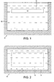
- the tank 11 shown in Figure 1 and 2 comprises a concrete enclosure 9m long, 6m wide and 8m in depth.
- the tank 11 is filled with sea water 12.
- a diaphragm 13 filled with fresh water 14 is located in the tank.
- the diaphragm 13 is 7.5m long, 4.25m wide and 0.25m thick and can be located at any desired height in a horizontal orientation within the tank 11.
- the conductivity of the sea water 12 was measured to be 5.3 S/m at 14°C and the conductivity of the fresh water was measured to be 0.013 S/m. The ratio of the two conductivities is therefore very close to 400.
- ⁇ r the relative dielectric constant of the medium
- ⁇ the conductivity in S/m.
- ⁇ r 80 at the frequencies and temperatures of interest.
- f c 1.2 GHz and 3 Mhz, respectively. Since, in the experiments, the highest frequency is 0.83 MHz, it is a fair approximation to neglect the displacement current, even for the fresh water.
- Each antenna 15 comprises two square brass plates 16, 15cm square, mounted on an epoxy substrate 17.
- Each plate 16 is connected to a co-axial cable 18, which passes through an epoxy tube 19 mounted at right angles to the plate 16, to a balun which transforms the impedance of the antenna 15 from about 2 ⁇ in sea water to about 50 ⁇ .
- the measurement set-up is shown in Figure 5 and 6 .
- An automatic network analyser measures the transmission between the antennae 15 as a function of distance (offset) and frequency.
- the arrangement shown in Figure 5 shows the antennae 15 in the parallel orientation.
- the in-line orientation is achieved by rotating both antennae through 90° in the horizontal plane.
- the parameters of the experiment are scaled relative to possible practical situations. To give an idea of orders of magnitude; if the frequency is scaled down by a factor of 40,000 and the conductivity by a factor of 10, the dimensions will be scaled up by a factor of 632, and the experimental setup would correspond to a low conductivity layer of thickness 150 m and conductivity 0.0013 S/m below an overburden of thickness 300 m and conductivity 0.52 S/m. The corresponding frequency range would be from 0.75 Hz to 20 Hz, and the length of the antenna nearly 300 m.
- the method with the TE and TM-mode have been tested by computer simulations on a simple horizontally layered earth model with electrical parameter values for typical deep water subsurface sediments.
- the model has an infinite insulating air layer, a 1150 meter water layer of 0.3125 ⁇ m , 950 meter overburden of 1 ⁇ m , a 150 meter reservoir zone of 50 ⁇ m and an infinite underburden of 1 ⁇ m .
- Figure 8 illustrates the amplitude response IEI (electric field) as a function of receiver offset, caused by a 1 Hz signal. Responses from both the TM-mode (solid with x's) and TE-mode (dashed with +'s) are shown.
- the amplitudes for the TM-mode are approximately 10 times larger at an offset of 5 km.
- the response from a homogenous half-space of 1 ⁇ m is shown for both configurations (corresponding to a response from a water filler reservoir or outside the reservoir area).
- the TE-mode has the largest deviation from its half-space, ie. this mode is more sensitive to a hydrocarbon layer.
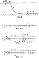
- Figures 9 and 10 show a vessel 31 towing a cable (or streamer) 32 just above the seabed 33.
- the cable 32 carries a transmitter dipole antenna 34 and several receiver dipoles 35, only four of which are shown.
- the depth of water might be of the order of 1000m
- the offset between the transmitter 34 and the nearest receiver 35 might be about 2000m
- the receivers might be about 100m apart.
- the transmitter 34 is controlled from the vessel 31 via the cable 32 and the responses detected by the receivers 35 are relayed back to the vessel 31 in real time, again via the cable 32.
- Figure 10 shows an arrangement in which the vessel 31 tows three cables 41, 42, 43, each carrying a series of receivers 45, 46, 47.
- the spacing of the three cables 41, 42, 43 is achieved by means of a spar 44.
- the transmitter 48 is in the form of two dipole antennae, one parallel to the cable 42 and one at right angles.
- the arrangement shown in Figure 12 is similar to Figure 11 , but in this case, the transmitter 51 is a single dipole antenna arranged at 45° to the cable 42.
Abstract
Description
- The present invention relates to a method and apparatus for determining the nature of submarine and subterranean reservoirs. The invention is particularly suitable for determining whether a reservoir, whose approximate geometry and location are known, contains hydrocarbons or water, though it can also be applied to detecting reservoirs with particular characteristics.
- Currently, the most widely used techniques for geological surveying, particularly in submarine situations, are seismic methods. These seismic techniques are capable of revealing the structure of the subterranean strata with some accuracy. However, whereas a seismic survey can reveal the location and shape of a potential reservoir, it cannot reveal the nature of the reservoir.
- The solution therefore is to drill a borehole into the reservoir. However, the costs involved in drilling an exploration well tend to be in the region of £25m and since the success rate is generally about 1 in 10, this tends to be a very costly exercise.
- It is therefore an object of the invention to provide a system for determining, with greater certainty, the nature of a subterranean reservoir without the need to sink a borehole.
- It has been appreciated by the present applicants that while the seismic properties of oil-filled strata and water-filled strata do not differ significantly, their electromagnetic resistivities (permittivities) do differ. Thus, by using an electromagnetic surveying method, these differences can be exploited and the success rate in predicting the nature of a reservoir can be increased significantly. This represents potentially an enormous cost saving.
- Consequently, a method and apparatus embodying these principles from the basis of the present applicant's co-pending International patent application
PCT/GB01/00419 - This contemplates a method of determining the nature of a subterranean reservoir whose approximate geometry and location are known, which comprises: applying a time varying electromagnetic field to the strata containing the reservoir; detecting the electromagnetic wave field response; seeking in the wave field response, a component representing a refracted wave from the hydrocarbon layer; and determining the content of the reservoir, based on the presence or absence of a wave component refracted by the hydrocarbon layer.
- It also contemplates a method for searching for a hydrocarbon containing subterranean reservoir which comprises: applying a time varying electromagnetic field to subterranean strata; detecting the electromagnetic wave field response; seeking, in the wave field response, a component representing a refracted wave; and determining the presence and/or nature of any reservoir identified based on the presence or absence of a wave component refracted by hydrocarbon layer.
- It further contemplates an apparatus for determining the nature of a subterranean reservoir whose approximate geometry and location are known, or for searching for a hydrocarbon containing subterranean reservoir, the apparatus comprising: means for applying a time varying electromagnetic field to the strata containing the reservoir; means for detecting the electromagnetic wave field response; and means for seeking, in the wave field response, a component representing a refracted wave, thereby enabling the presence and/or nature of a reservoir to be determined.
- A refracted wave behaves differently, depending on the nature of the stratum in which it is propagated. In particular, the propagation losses in hydrocarbon stratum are much lower than in a water-bearing stratum while the speed of propagation is much higher. Thus, when an oil-bearing reservoir is present, and an EM field is applied, a strong and rapidly propagated refracted wave can be detected. This may therefore indicate the presence of the reservoir or its nature if its presence is already known.
- Electromagnetic surveying techniques in themselves are known see for example patent publication
US 2,077,707 ,US 4,617,518 orUS 4,258,321 . However, they are not widely used in practice. In general, the reservoirs of interest are about 1 km or more below the seabed. In order to carry out electromagnetic surveying as a stand alone technique in these conditions, with any reasonable degree of resolution, short wavelengths are necessary. Unfortunately, such short wavelengths suffer from very high attenuation. Long wavelengths do not provide adequate resolution. For these reasons, seismic techniques are preferred. - However, while longer wavelengths applied by electromagnetic techniques cannot provide sufficient information to provide an accurate indication of the boundaries of the various strata, if the geological structure is already known, they can be used to determine the nature of a particular identified formation, if the possibilities for the nature of that formation have significantly differing electromagnetic characteristics. The resolution is not particularly important and so longer wavelengths which do not suffer from excessive attenuation can be employed.
- The resistivity of seawater is about 0.3 ohm-m and that of the overburden beneath the seabed would typically be from 0.3 to 4 ohm-m, for example about 2 ohm-m. However, the resistivity of an oil reservoir is likely to be about 20-300 ohm-m. This large difference can be exploited using the techniques of the present invention.
- Typically, the resistivity of a hydrocarbon-bearing formation will be 20 to 300 times greater than water-bearing formation.
- Due to the different electromagnetic properties of a gas/oil bearing formation and a water bearing formation, one can expect a reflection and refraction of the transmitted field at the boundary of a gas/oil bearing formation. However, the similarity between the properties of the overburden and a reservoir containing water means that no reflection or refraction is likely to occur.
- Thus, an electric dipole transmitter antenna on or close to the sea floor induces electromagnetic (EM) fields and currents in the sea water and in the subsurface strata. In the sea water, the EM-fields are strongly attenuated due to the high conductivity in the saline environment, whereas the subsurface strata with less conductivity potentially can act as a guide for the EM-fields (less attenuation). If the frequency is low enough (in the order of 1 Hz), the EM-waves are able to penetrate deep into the subsurface, and deeply buried geological layers having higher electrical resistivity than the overburden (as e.g. a hydrocarbon filled reservoir) will affect the EM-waves. Depending on the angle of incidence and state of polarisation, an EM wave incident upon a high resistive layer may excite a ducted (guided) wave mode in the layer. The ducted mode is propagated laterally along the layer and leaks energy back to the overburden and receivers positioned on the sea floor. The term "refracted" wave in this specification is intended to refer to this wave mode.
- Both theory and laboratory experiments show that the ducted mode is excited only for an incident wave with transverse magnetic (TM) polarisation (magnetic field perpendicular to the plane of incidence) and at angles of incidence close to the Brewster angle and the critical angle (the angle of total reflection). For transverse electric (TE) polarisation (electric field perpendicular to the plane of incidence) the ducted mode will not be excited. Since the induced current is proportional to the electric field, the current will be parallel to the layer interfaces for TE polarisation but, for TM polarisation, there is an appreciable current across the layer interfaces.
- A horizontal dipole source on the sea floor will generate both TE and TM waves, but by varying the orientation of the receiver antennae, it is possible to vary the sensitivity to the two modes of polarisation. It appears that an in-line orientation (source and receiver dipoles in-line) is more sensitive to the TM mode of polarisation, whereas a parallel orientation (source and receiver dipoles in parallel) is more sensitive to the TE mode of polarisation. The TM mode is influenced by the presence of buried high resistive layers, whereas the TE mode is not. By measuring with the two antenna configurations and exploiting the difference between the two sets of measurements, it is possible to identify deeply buried high resistivity zones, i.e. a hydrocarbon reservoir.
-
US 4,258,321 is concerned with geophysical surveying using radio waves. The relative magnitude and phase of radio frequency signal components reflected from subterranean formations are measured at several positions along a survey path. At each position, data is taken for the alignment of electric and magnetic vector fields. - The present invention has arisen from this realisation and comprises methods as set forth in the
independent claims - According to one aspect of the present invention, there is provided, a method of determining whether a subterranean reservoir whose approximate geometry and location are known, contains hydrocarbons or water, which method comprises: deploying an electric dipole transmitter antenna with its axis generally horizontal; deploying an electric dipole receiver antenna in-line with the transmitter; applying an electromagnetic (EM) field to the strata containing the reservoir using the transmitter and detecting the EM wave field response using the receiver; identifying in the response a component representing a ducted wave from the reservoir according to a first mode; deploying an electric dipole receiver antenna parallel to the transmitter; applying an EM field to the strata using the transmitter; detecting the EM wave field response using the receiver, identifying in the response a component representing a ducted wave from the reservoir according to a second mode; and comparing the first mode ducted wave response with the second mode ducted wave response in order to determine whether the reservoir contains hydrocarbons or water.
- According to another aspect of the present invention there is provided, a method of searching for a hydrocarbon-containing subterranean reservoir which comprises: deploying an electric dipole transmitter antenna with its axis generally horizontal; deploying an electric dipole receiver antenna in-line with the transmitter; applying an EM field to subterranean strata using the transmitter; detecting the EM wave field response using the receiver; seeking in the response a component representing a ducted wave according to a first mode, caused by a high-resistivity zone; deploying an electric dipole receiver antenna parallel to the transmitter; applying an EM field to the strata using the transmitter; detecting the EM wave field response using the receiver; seeking in the response a component representing a ducted wave according to a second mode; and comparing the first mode ducted wave response with the second mode ducted wave response in order to determine the presence and/or nature of any high-resistivity zone.
- The first mode may be considered to be a TM mode, and the second mode a TE mode.
- Thus, according to the invention, measurements are taken with the transmitter and receiver both in-line and parallel, and the two sets of measurements are compared. A characteristic difference in values indicates a highly resistive layer located beneath highly conductive strata. High resistivity indicates the presence of hydrocarbons and so the difference in values is a direct hydrocarbon indicator.
- This technique can be used in conjunction with conventional seismic techniques to identify hydrocarbon reservoirs.
- Preferably, the transmitter and/or receiver comprises an array of dipole antennae.
- The technique is applicable in exploring land-based subterranean reservoirs but is especially applicable to submarine, in particular sub-sea, subterranean reservoirs. Preferably the field is applied using one or more transmitters located on the earth's surface, and the detection is carried out by one or more receivers located on the earth's surface. In a preferred application, the transmitter(s) and/or receivers are located on or close to the seabed or the bed of some other area of water.
- In a preferred arrangement, the transmitter and receiver antennae are located on a common cable towed behind a vessel. This will result in a fixed offset or a series of fixed offsets where several receivers are employed. Preferably, the transmitter transmits both modes and may therefore comprise two dipoles arranged mutually at right angles. Preferably each receiver comprises two dipoles mutually at right angles. Preferably one transmitter dipole and one receiver dipole are arranged at right angles to the direction of the cable. Alternatively the transmitter and/or receivers may each comprise a single dipole antenna arranged obliquely, eg. at 45° to the direction of the cable. With this arrangement the transmitted field is resolved.
- Using this technique, it is possible to achieve comparable results from the two modes as the same signal and offset are used. It will not matter greatly if the transmitter drifts in frequency or amplitude. Furthermore, reservoirs can be detected in real time. Thus, if the results show a difference in the two modes, this will strongly indicate the presence of an H/C bearing reservoir and so a more detailed study can be made at once.
- Such a system would generally use a single transmission source and several receivers, typically more than ten. The different offsets would be suitable for detecting reservoirs at different depths.
- The receivers can be deployed on a single cable or on a series of parallel cables. There may also be several transmitters.
- In practice, the vessel would normally stop and the cable allowed to sink prior to transmission. There would be a transmission at several different frequencies before moving to another location. The technique is particularly suitable for edge detection, and it is a simple matter to select a suitable resolution. However, if the surveying is being carried out in an undetermined area, the resistivity in the top layers should be mapped, for example with MT methods or by inversion after a reflection study.
- If the offset between the transmitter and receiver is significantly greater than three times the depth of the reservoir from the seabed (i.e. the thickness of the overburden), it will be appreciated that the attenuation of the refracted wave will often be less than that of direct wave and the reflected wave. The reason for this is the fact that the path of the refracted wave will be effectively distance from the transmitter down to the reservoir i.e. the thickness of the overburden, plus the offset along the reservoir, plus the distance from the reservoir up to the receivers i.e. once again the thickness of the overburden.
- The polarization of the source transmission will determine how much energy is transmitted into the oil-bearing layer in the direction of the receiver. A dipole antenna is therefore the selected transmitter. In general, it is preferable to adopt a dipole with a large effective length. The transmitter dipole may therefore be 100 to 1000 meters in length and may be towed in two orthogonal directions. The receiver dipole optimum length is determined by the thickness of the overburden.
- The transmitted field may be pulsed, however, a coherent continuous wave with stepped frequencies is preferred. It may be transmitted for a significant period of time, during which the transmitter should preferably be stationary (although it could be moving slowly), and the transmission stable. Thus, the field may be transmitted for a period of time from 3 seconds to 60 minutes, preferably from 3 to 30 minutes, for example about 20 minutes. The receivers may also be arranged to detect a direct wave and a wave refracted from the reservoir, and the analysis may include extracting phase and amplitude data of the refracted wave from corresponding data from the direct wave.
- Preferably, the wavelength of the transmission should be in the range

- Preferably, the distance between the transmitter and a receiver should be in the range

- It will be appreciated that the present invention may be used to determine the position, the extent, the nature and the volume of a particular stratum, and may also be used to detect changes in these parameters over a period of time.
- The present invention also extends to a method of surveying subterranean measures which comprises; performing a seismic survey to determine the geological structure of a region; and where that survey reveals the presence of a subterranean reservoir, subsequently performing a method as described above.
- The invention may be carried into practice in various ways and will now be illustrated in the following embodiments and reduced scale investigations and simulations. In the accompanying drawings,
-
Figure 1 is a vertical cross-section through a testing tank; -
Figure 2 is a plan view of the tank ofFigure 1 ; -
Figure 3 is a plan view of the antennae used in the tank ofFigure 1 ; -
Figure 4 is a side view of the antenna inFigure 3 ; -
Figures 5 and 6 are respectively a schematic plan view and side view of the testing tank set up for measurement; -
Figures 7 is a graph showing calculated and measured values for the transmitted electric field for a given frequency in the model experiment; -
Figure 8 is a graph showing calculated values for the electric field in a realistic earth model; -
Figure 9 is a schematic side view of a cable layout towed by a vessel; -
Figure 10 is a plan view corresponding toFigure 9 ; and -
Figures 11 and 12 are views similar toFigure 10 showing two alternative arrangements. - The
tank 11 shown inFigure 1 and 2 comprises a concrete enclosure 9m long, 6m wide and 8m in depth. Thetank 11 is filled withsea water 12. Adiaphragm 13 filled withfresh water 14 is located in the tank. Thediaphragm 13 is 7.5m long, 4.25m wide and 0.25m thick and can be located at any desired height in a horizontal orientation within thetank 11. - The conductivity of the
sea water 12 was measured to be 5.3 S/m at 14°C and the conductivity of the fresh water was measured to be 0.013 S/m. The ratio of the two conductivities is therefore very close to 400. - The critical frequency fc of a conducting medium, i.e. the frequency at which the displacement current is equal to the conduction current, is given by

- For a non magnetic, conductive medium, the propagation constant γ is given by

- The wavelength λ, defined as the distance in which the phase changes 2π, is given by


- For the extremes of the frequency range, for the sea water with σ=5.2 S/m,
Frequency 30 kHz 830 kHz Skin depth 1.27 m 0.24 m Wavelength 8.01 m 1.52 m Frequency 30 kHz 830 kHz Skin depth 25.4 m 4.8 m Wavelength 160.2 m 30.4 m - Referring now to
Figures 3 and 4 , two identical electrical dipole antennae, as shown were used for the transmitter and receiver. - Each
antenna 15 comprises twosquare brass plates 16, 15cm square, mounted on anepoxy substrate 17. Eachplate 16 is connected to aco-axial cable 18, which passes through anepoxy tube 19 mounted at right angles to theplate 16, to a balun which transforms the impedance of theantenna 15 from about 2Ω in sea water to about 50Ω. - The measurement set-up is shown in
Figure 5 and 6 . An automatic network analyser (ANA) measures the transmission between theantennae 15 as a function of distance (offset) and frequency. The arrangement shown inFigure 5 shows theantennae 15 in the parallel orientation. The in-line orientation is achieved by rotating both antennae through 90° in the horizontal plane. - The results of the measurements are shown in
Figure 7 together with the corresponding theoretical results. The measurements agree well with the theoretical results and the figure contains two sets of curves, one with parallel antennae and one with the antennae in line. The theoretical results are computed for infinitesimal dipole antennae. The orientations of the antennae and the frequency are shown on the Figures. - The parameters of the experiment are scaled relative to possible practical situations.
To give an idea of orders of magnitude; if the frequency is scaled down by a factor of 40,000 and the conductivity by a factor of 10, the dimensions will be scaled up by a factor of 632, and the experimental setup would correspond to a low conductivity layer of thickness 150 m and conductivity 0.0013 S/m below an overburden of thickness 300 m and conductivity 0.52 S/m. The corresponding frequency range would be from 0.75 Hz to 20 Hz, and the length of the antenna nearly 300 m. - The method with the TE and TM-mode have been tested by computer simulations on a simple horizontally layered earth model with electrical parameter values for typical deep water subsurface sediments. The model has an infinite insulating air layer, a 1150 meter water layer of 0.3125Ωm, 950 meter overburden of 1Ωm, a 150 meter reservoir zone of 50Ωm and an infinite underburden of 1Ωm.
Figure 8 illustrates the amplitude response IEI (electric field) as a function of receiver offset, caused by a 1 Hz signal. Responses from both the TM-mode (solid with x's) and TE-mode (dashed with +'s) are shown. The amplitudes for the TM-mode are approximately 10 times larger at an offset of 5 km. As a reference, the response from a homogenous half-space of 1Ωm is shown for both configurations (corresponding to a response from a water filler reservoir or outside the reservoir area). The TE-mode has the largest deviation from its half-space, ie. this mode is more sensitive to a hydrocarbon layer. -
Figures 9 and 10 show avessel 31 towing a cable (or streamer) 32 just above theseabed 33. Thecable 32 carries atransmitter dipole antenna 34 andseveral receiver dipoles 35, only four of which are shown. The depth of water might be of the order of 1000m, the offset between thetransmitter 34 and thenearest receiver 35 might be about 2000m and the receivers might be about 100m apart. Thetransmitter 34 is controlled from thevessel 31 via thecable 32 and the responses detected by thereceivers 35 are relayed back to thevessel 31 in real time, again via thecable 32. -
Figure 10 shows an arrangement in which thevessel 31 tows threecables receivers cables spar 44. - In the arrangement shown in
Figure 11 , thetransmitter 48 is in the form of two dipole antennae, one parallel to thecable 42 and one at right angles. - The arrangement shown in
Figure 12 is similar toFigure 11 , but in this case, thetransmitter 51 is a single dipole antenna arranged at 45° to thecable 42.
Claims (14)
- A method of determining whether a subterranean reservoir, whose approximate geometry and location are known, contains hydrocarbons or water, which method comprises deploying an electric dipole transmitter antenna (34) with its axis generally horizontal, deploying an electric dipole receiver antenna (35) in-line with the transmitter (34), applying an electromagnetic (EM) field to the strata containing the reservoir using the transmitter and detecting the EM wave field response using the receiver characterised by: identifying in the response a component representing a ducted wave from the reservoir according to a first mode; deploying an electric dipole receiver antenna (35) parallel to the transmitter; applying an EM field to the strata using the transmitter; detecting the EM wave field response using the receiver and identifying in the response a component representing a ducted wave from the reservoir according to a second mode; and comparing the first mode ducted wave response with the second mode ducted wave response in order to determine whether the reservoir contains hydrocarbons or water.
- A method of searching for a hydrocarbon-containing subterranean reservoir which comprises deploying an electric dipole transmitter antenna (34) with its axis generally horizontal, deploying an electric dipole receiver antenna (35) in-line with the transmitter, applying an EM field to subterranean strata using the transmitter and detecting the EM wave field response using the receiver characterised by: seeking in the response a component representing a ducted wave according to a first mode, caused by a high-resistivity zone; deploying an electric dipole receiver antenna (35) parallel to the transmitter; applying an EM field to the strata using the transmitter; detecting the EM wave field response using the receiver; seeking in the response a component representing a ducted wave according to a second mode; and comparing the first mode ducted wave response with the second mode ducted wave response in order to determine the presence and/or nature of any high-resistivity zone.
- A method as claimed in Claim 1 or Claim 2, characterised in that the first mode is a TM mode of polarisation and/or the second mode is a TE mode of polarisation.
- A method as claimed in any preceding Claim, characterised in that the transmitter (34) and/or receiver (35) comprises an array of dipole antennae.
- A method as claimed in any preceding Claim, characterised in that the transmitter and/or receiver (34,35) is located on or close to the seabed (33) or the bed of some other area of water.
- A method as claimed in any preceding Claim, characterised in that the transmitter (34) and receivers (35) are located on a common cable (32) arranged to be towed behind a vessel (31).
- A method as claimed in Claim 6 characterised in that the transmitter (51) and/or receiver each comprise two dipole antennae (34,35) arranged mutually at right angles.
- A method as claimed in any preceding Claim, characterised in that the frequency of the EM field is continuously varied over the transmission period.
- A method as claimed in any preceding Claim, characterised in that the field is transmitted for a period of time for 3 seconds to 60 minutes, preferably from 3 to 30 minutes.
- A method as claimed in any preceding Claim, characterised in that the wavelength of the transmission is given by the formula

- A method as claimed in any preceding Claim, characterised in that distance between the transmitter and a receiver is given by the formula

- A method as claimed in any of Claims 8 to 11, characterised in that the transmission frequency is from 0.01 Hz to 1 kHz, preferably from 1 to 20 Hz.
- A method as claimed in any preceding Claim, characterised in that it includes suppressing the direct wave and/or any other known wave contribution that may disturb the measurements, thereby reducing the required dynamic range of the receiver (35) and increasing the resolution of the refracted wave.
- A method of surveying subterranean measures which comprises: performing a seismic survey to determine the geological structure of a region and where that survey reveals the presence of a subterranean reservoir, subsequently performing a method as claimed in any preceding Claim.
Applications Claiming Priority (5)
| Application Number | Priority Date | Filing Date | Title |
|---|---|---|---|
| GB0019956 | 2000-08-14 | ||
| GB0019956A GB0019956D0 (en) | 2000-08-14 | 2000-08-14 | Method and apparatus for determining the nature of subterranean reservoirs |
| GBGB0023921.0A GB0023921D0 (en) | 2000-09-29 | 2000-09-29 | Method and apparatus for determining the nature of subterranean reservoirs |
| GB0023921 | 2000-09-29 | ||
| PCT/GB2001/003473 WO2002014906A1 (en) | 2000-08-14 | 2001-08-02 | Method and apparatus for determining the nature of subterranean reservoirs |
Publications (3)
| Publication Number | Publication Date |
|---|---|
| EP1309887A1 EP1309887A1 (en) | 2003-05-14 |
| EP1309887B1 EP1309887B1 (en) | 2004-03-31 |
| EP1309887B2 true EP1309887B2 (en) | 2017-07-19 |
Family
ID=26244836
Family Applications (1)
| Application Number | Title | Priority Date | Filing Date |
|---|---|---|---|
| EP01956656.1A Expired - Lifetime EP1309887B2 (en) | 2000-08-14 | 2001-08-02 | Method and apparatus for determining the nature of subterranean reservoirs |
Country Status (16)
| Country | Link |
|---|---|
| US (2) | US7038456B2 (en) |
| EP (1) | EP1309887B2 (en) |
| CN (1) | CN1246706C (en) |
| AT (1) | ATE263383T1 (en) |
| AU (3) | AU2001278580B2 (en) |
| BR (2) | BR0113208A (en) |
| CA (1) | CA2417832C (en) |
| DE (1) | DE60102595T2 (en) |
| DK (1) | DK1309887T4 (en) |
| EG (1) | EG22885A (en) |
| ES (1) | ES2218438T3 (en) |
| MX (1) | MXPA03001367A (en) |
| MY (1) | MY127089A (en) |
| NO (1) | NO324897B1 (en) |
| PT (1) | PT1309887E (en) |
| WO (1) | WO2002014906A1 (en) |
Families Citing this family (87)
| Publication number | Priority date | Publication date | Assignee | Title |
|---|---|---|---|---|
| GB9818875D0 (en) | 1998-08-28 | 1998-10-21 | Norske Stats Oljeselskap | Method and apparatus for determining the nature of subterranean reservoirs |
| GB0002422D0 (en) * | 2000-02-02 | 2000-03-22 | Norske Stats Oljeselskap | Method and apparatus for determining the nature of subterranean reservoirs |
| PT1309887E (en) * | 2000-08-14 | 2004-08-31 | Statoil Asa | METHOD AND APPARATUS FOR DETERMINING THE NATURE OF UNDERGROUND RESERVOIRS |
| GB2383133A (en) * | 2001-08-07 | 2003-06-18 | Statoil Asa | Investigation of subterranean reservoirs |
| GB2378511B (en) * | 2001-08-07 | 2005-12-28 | Statoil Asa | Method and apparatus for determining the nature of subterranean reservoirs |
| GB2385923B (en) | 2002-05-24 | 2004-07-28 | Statoil Asa | System and method for electromagnetic wavefield resolution |
| US6842006B2 (en) | 2002-06-27 | 2005-01-11 | Schlumberger Technology Corporation | Marine electromagnetic measurement system |
| GB2390904B (en) | 2002-07-16 | 2004-12-15 | Univ Southampton | Electromagnetic surveying for hydrocarbon reservoirs |
| GB2395563B (en) | 2002-11-25 | 2004-12-01 | Activeem Ltd | Electromagnetic surveying for hydrocarbon reservoirs |
| RU2335788C2 (en) * | 2002-12-10 | 2008-10-10 | Дзе Риджентс Оф Дзе Юниверсити Оф Калифорния | System and method of hydrocarbon deposit control of using adjustable electromagnetic transmitter |
| US7023213B2 (en) | 2002-12-10 | 2006-04-04 | Schlumberger Technology Corporation | Subsurface conductivity imaging systems and methods |
| GB2399640B (en) * | 2003-03-17 | 2007-02-21 | Statoil Asa | Method and apparatus for determining the nature of submarine reservoirs |
| GB2402745B (en) * | 2003-06-10 | 2005-08-24 | Activeem Ltd | Electromagnetic surveying for hydrocarbon reservoirs |
| US7228903B2 (en) * | 2003-07-08 | 2007-06-12 | Baker Hughes Incorporated | Apparatus and method for wireline imaging in nonconductive muds |
| GB2409900B (en) | 2004-01-09 | 2006-05-24 | Statoil Asa | Processing seismic data representing a physical system |
| GB2411006B (en) | 2004-02-16 | 2006-01-25 | Ohm Ltd | Electromagnetic surveying for hydrocarbon reservoirs |
| GB2413851B (en) | 2004-05-06 | 2006-08-09 | Ohm Ltd | Electromagnetic surveying for hydrocarbon reservoirs |
| GB2420855B (en) * | 2004-12-02 | 2009-08-26 | Electromagnetic Geoservices As | Source for electromagnetic surveying |
| GB2422673B (en) * | 2005-02-01 | 2010-03-24 | Electromagnetic Geoservices As | Optimum signal for sea bed logging |
| GB2423370B (en) | 2005-02-22 | 2007-05-02 | Ohm Ltd | Electromagnetic surveying for resistive or conductive bodies |
| US7295013B2 (en) | 2005-04-11 | 2007-11-13 | Schlumberger Technology Corporation | Remotely operable measurement system and method employing same |
| US7894989B2 (en) | 2005-06-09 | 2011-02-22 | Exxonmobil Upstream Research Co. | Method for determining earth vertical electrical anisotropy in marine electromagnetic surveys |
| BRPI0611722A2 (en) | 2005-06-10 | 2012-07-31 | Exxonmobil Upstream Res Co | Methods for identifying resistive anomalies in a controlled source electromagnetic survey of the subsurface of a survey area, for conducting a controlled source electromagnetic survey of the subsurface of a survey area, and for producing hydrocarbons from an underground region. |
| US7330790B2 (en) * | 2005-10-03 | 2008-02-12 | Seismic Sciences, Inc. | Method of seismo electromagnetic detecting of hydrocarbon deposits |
| US7411399B2 (en) | 2005-10-04 | 2008-08-12 | Schlumberger Technology Corporation | Electromagnetic survey system with multiple sources |
| NO323889B1 (en) | 2005-11-03 | 2007-07-16 | Advanced Hydrocarbon Mapping A | Process for mapping hydrocarbon reservoirs and apparatus for use in carrying out the process |
| US7884612B2 (en) * | 2005-12-22 | 2011-02-08 | Westerngeco L.L.C. | Multi-component field sources for subsea exploration |
| GB2434868B (en) | 2006-02-06 | 2010-05-12 | Statoil Asa | Method of conducting a seismic survey |
| GB2435693A (en) * | 2006-02-09 | 2007-09-05 | Electromagnetic Geoservices As | Seabed electromagnetic surveying |
| NO326957B1 (en) * | 2006-02-13 | 2009-03-23 | Norsk Hydro As | Electromagnetic method on shallow water using controlled source |
| US8165815B2 (en) | 2006-02-21 | 2012-04-24 | Exxonmobil Upstream Research Co. | Method for electromagnetic air-wave suppression by active cancellation and shielding |
| US20070216416A1 (en) * | 2006-03-15 | 2007-09-20 | Baker Hughes Incorporated | Electromagnetic and Magnetostatic Shield To Perform Measurements Ahead of the Drill Bit |
| GB2442849B (en) * | 2006-03-29 | 2008-08-20 | Pgs Geophysical As | Low noise towed electromagnetic system for subsurface exploration |
| US7471089B2 (en) | 2006-04-24 | 2008-12-30 | Schlumberger Technology Corporation | Electrode array for marine electric and magnetic field measurements having first and second sets of electrodes connected to respective first and second cables |
| US8437961B2 (en) | 2006-05-04 | 2013-05-07 | Exxonmobil Upstream Research Company | Time lapse analysis with electromagnetic data |
| GB2439378B (en) * | 2006-06-09 | 2011-03-16 | Electromagnetic Geoservices As | Instrument for measuring electromagnetic signals |
| US7860655B2 (en) | 2006-07-14 | 2010-12-28 | Westerngeco L.L.C. | Electromagnetically detecting thin resistive bodies in shallow water and terrestrial environments |
| US7657391B2 (en) | 2006-07-14 | 2010-02-02 | Westerngeco L.L.C. | Electromagnetically detecting thin resistive bodies in shallow water and terrestrial environments |
| GB2441786A (en) * | 2006-09-15 | 2008-03-19 | Electromagnetic Geoservices As | Combined electromagnetic and seismic surveying |
| GB2442749B (en) | 2006-10-12 | 2010-05-19 | Electromagnetic Geoservices As | Positioning system |
| US7400977B2 (en) | 2006-10-12 | 2008-07-15 | Schlumberger Technology Corporation | Computing values for surveying a subterranean structure based on measurements according to different electromagnetic survey techniques |
| US7504829B2 (en) * | 2006-10-24 | 2009-03-17 | Westerngeco L.L.C. | Methods and apparatus for subsurface geophysical exploration using joint inversion of steady-state and transient data |
| US7430474B2 (en) | 2006-10-31 | 2008-09-30 | Schlumberger Technology Corporation | Removing sea surface-related electromagnetic fields in performing an electromagnetic survey |
| US7667464B2 (en) | 2006-11-02 | 2010-02-23 | Westerngeco L.L.C. | Time segmentation of frequencies in controlled source electromagnetic (CSEM) applications |
| NO326978B1 (en) * | 2006-11-27 | 2009-03-30 | Advanced Hydrocarbon Mapping As | Process for mapping hydrocarbon reservoirs in shallow water and apparatus for use in carrying out the process |
| GB2445582A (en) | 2007-01-09 | 2008-07-16 | Statoil Asa | Method for analysing data from an electromagnetic survey |
| WO2008094128A1 (en) * | 2007-01-29 | 2008-08-07 | Agency For Science, Technology And Research | Antenna for underwater communications |
| NO330103B1 (en) | 2007-02-09 | 2011-02-21 | Statoil Asa | Assembly for drilling and logging, method for electropulse drilling and logging |
| US7659724B2 (en) | 2007-03-29 | 2010-02-09 | Westerngeco L.L.C. | Surveying method using an arrangement of plural signal sources |
| US7633296B2 (en) | 2007-03-30 | 2009-12-15 | Westerngeco L.L.C. | Receivers and methods for electromagnetic measurements |
| US7826972B2 (en) | 2007-03-30 | 2010-11-02 | Westerngeco L.L.C | Methods of electromagnetic logging using a current focusing receiver |
| US7640110B2 (en) * | 2007-04-27 | 2009-12-29 | Schlumberger Technology Corporation | Pixel based inversion method for surface electromagnetic measurement |
| US8026723B2 (en) * | 2007-04-30 | 2011-09-27 | Kjt Enterprises, Inc. | Multi-component marine electromagnetic signal acquisition method |
| US7746077B2 (en) * | 2007-04-30 | 2010-06-29 | Kjt Enterprises, Inc. | Method for measuring the magnetotelluric response to the earth's subsurface |
| US7872477B2 (en) * | 2007-04-30 | 2011-01-18 | Kjt Enterprises, Inc. | Multi-component marine electromagnetic signal acquisition cable and system |
| CA2687311A1 (en) | 2007-05-14 | 2009-03-19 | Ocean Floor Geophysics, Inc. | Underwater electric field electromagnetic prospecting system |
| US7863901B2 (en) * | 2007-05-25 | 2011-01-04 | Schlumberger Technology Corporation | Applications of wideband EM measurements for determining reservoir formation properties |
| US7705599B2 (en) * | 2007-07-09 | 2010-04-27 | Kjt Enterprises, Inc. | Buoy-based marine electromagnetic signal acquisition system |
| US7852087B2 (en) * | 2007-08-10 | 2010-12-14 | Schlumberger Technology Corporation | Removing effects of near surface geology from surface-to-borehole electromagnetic data |
| US7949470B2 (en) | 2007-11-21 | 2011-05-24 | Westerngeco L.L.C. | Processing measurement data in a deep water application |
| US7671598B2 (en) * | 2007-12-03 | 2010-03-02 | Pgs Geophysical As | Method and apparatus for reducing induction noise in measurements made with a towed electromagnetic survey system |
| US7834632B2 (en) | 2007-12-03 | 2010-11-16 | Pgs Geophysical As | Receiver streamer system and method for marine electromagnetic surveying |
| US7660671B2 (en) * | 2007-12-06 | 2010-02-09 | Schlumberger Technology Corporation | Method and apparatus for electromagnetic logging of a formation |
| US8547783B2 (en) * | 2007-12-12 | 2013-10-01 | Exxonmobil Upstream Research Company | Method and apparatus for evaluating submarine formations |
| US20090265111A1 (en) * | 2008-04-16 | 2009-10-22 | Kjt Enterprises, Inc. | Signal processing method for marine electromagnetic signals |
| US7999552B2 (en) * | 2008-06-03 | 2011-08-16 | Westerngeco L.L.C. | Sensor cable for electromagnetic surveying |
| US8080999B2 (en) * | 2008-07-05 | 2011-12-20 | Westerngeco L.L.C. | Sensor cable for electromagnetic surveying |
| US7861801B2 (en) * | 2008-07-07 | 2011-01-04 | Bp Corporation North America Inc. | Method to detect coring point from resistivity measurements |
| US8499830B2 (en) * | 2008-07-07 | 2013-08-06 | Bp Corporation North America Inc. | Method to detect casing point in a well from resistivity ahead of the bit |
| US8061442B2 (en) * | 2008-07-07 | 2011-11-22 | Bp Corporation North America Inc. | Method to detect formation pore pressure from resistivity measurements ahead of the bit during drilling of a well |
| US8228208B2 (en) * | 2008-07-28 | 2012-07-24 | Westerngeco L.L.C. | Communication system for survey source and receiver |
| US20100045296A1 (en) * | 2008-08-19 | 2010-02-25 | Pgs Geophysical As | Cable system for marine data acquisition |
| GB2466764B (en) | 2008-10-02 | 2013-03-27 | Electromagnetic Geoservices As | Method for enhanced subsurface electromagnetic sensitivity |
| US8164340B2 (en) * | 2008-10-23 | 2012-04-24 | Kjt Enterprises, Inc. | Method for determining electromagnetic survey sensor orientation |
| EP2376952A4 (en) * | 2008-12-15 | 2017-03-01 | The Governing Council Of The University Of Toronto | A continuously towed seafloor electromagnetic prospecting system |
| US8143897B2 (en) * | 2009-02-11 | 2012-03-27 | Mtem Ltd. | Short-offset transient electromagnetic geophysical surveying |
| US8729903B2 (en) * | 2009-11-09 | 2014-05-20 | Exxonmobil Upstream Research Company | Method for remote identification and characterization of hydrocarbon source rocks using seismic and electromagnetic geophysical data |
| US20110255368A1 (en) * | 2010-04-14 | 2011-10-20 | S Dow Gustav G Ran Mattias | Method for 2D and 3D electromagnetic field measurements using a towed marine electromagnetic survey system |
| US9588250B2 (en) | 2010-04-14 | 2017-03-07 | Baker Hughes Incorporated | Three-coil system with short nonconductive inserts for transient MWD resistivity measurements |
| US8575938B2 (en) * | 2010-04-20 | 2013-11-05 | Pgs Geophysical As | Electrical power system for towed electromagnetic survey streamers |
| GB2481845B (en) | 2010-07-08 | 2014-04-30 | Electromagnetic Geoservices As | Low noise marine electric field sensor system |
| CN102466822B (en) * | 2010-11-04 | 2013-09-04 | 中国石油天然气集团公司 | Ocean electromagnetic surveying four-pole mutual combination pole distribution method |
| US20120194196A1 (en) * | 2011-02-02 | 2012-08-02 | Leendert Combee | Electromagnetic Source to Produce Multiple Electromagnetic Components |
| US8587316B2 (en) | 2011-12-08 | 2013-11-19 | Pgs Geophysical As | Noise reduction systems and methods for a geophysical survey cable |
| US8736269B2 (en) | 2011-12-27 | 2014-05-27 | Pgs Geophysical As | Electromagnetic geophysical survey systems and methods employing electric potential mapping |
| US8922214B2 (en) | 2011-12-27 | 2014-12-30 | Pgs Geophysical As | Electromagnetic geophysical survey systems and methods employing electric potential mapping |
| US9239401B2 (en) * | 2012-03-01 | 2016-01-19 | Pgs Geophysical As | Stationary source for marine electromagnetic surveying |
Citations (3)
| Publication number | Priority date | Publication date | Assignee | Title |
|---|---|---|---|---|
| US2077707A (en) † | 1933-08-01 | 1937-04-20 | Melton Benjamin Starr | Electromagnetic prospecting method |
| US4617518A (en) † | 1983-11-21 | 1986-10-14 | Exxon Production Research Co. | Method and apparatus for offshore electromagnetic sounding utilizing wavelength effects to determine optimum source and detector positions |
| WO2000013046A1 (en) † | 1998-08-28 | 2000-03-09 | Den Norske Stats Oljeselskap A.S. | Method and apparatus for determining the nature of subterranean reservoirs |
Family Cites Families (70)
| Publication number | Priority date | Publication date | Assignee | Title |
|---|---|---|---|---|
| US2531088A (en) * | 1947-10-16 | 1950-11-21 | Standard Oil Dev Co | Electrical prospecting method |
| US3052836A (en) * | 1957-12-24 | 1962-09-04 | Shell Oil Co | Method for marine electrical prospecting |
| US3398356A (en) * | 1964-02-10 | 1968-08-20 | Westinghouse Electric Corp | Method utilizing a pair of subsurface antennas for determining the physical properties effecting radio energy propagation through earth |
| GB1239953A (en) * | 1967-06-06 | 1971-07-21 | Rech S Geol Et Minieres Bureau | Improvements in or relating to methods and apparatus for determining the electrical resistance of the sub-soil |
| US4010413A (en) * | 1971-08-23 | 1977-03-01 | Geo-Nav, Inc. | Plural frequency geological exploration system and method with phase comparison |
| US3806795A (en) * | 1972-01-03 | 1974-04-23 | Geophysical Survey Sys Inc | Geophysical surveying system employing electromagnetic impulses |
| FR2288988A1 (en) * | 1974-07-30 | 1976-05-21 | Duroux Jean | METHOD AND APPARATUS FOR PROSPECTING AT SEA BY MEASURING ELECTROMAGNETIC FIELDS |
| US4079309A (en) * | 1976-09-03 | 1978-03-14 | The United States Of America As Represented By The Secretary Of The Navy | Method for determining changes in earth resistivity by measuring phase difference between magnetic field components |
| FR2390743A1 (en) * | 1977-05-09 | 1978-12-08 | Geophysique Cie Gle | ELECTROMAGNETIC PROSPECTION OF THE BASEMENT BY INDUCTION, ASSOCIATED WITH PROSPECTION BY ELECTRIC SURVEY |
| US4258321A (en) * | 1978-03-09 | 1981-03-24 | Neale Jr Dory J | Radio geophysical surveying method and apparatus |
| US4308499A (en) * | 1978-05-26 | 1981-12-29 | Kali Und Salz A.G. | Method utilizing electromagnetic wave pulses for determining the locations of boundary surfaces of underground mineral deposits |
| US4446434A (en) * | 1978-12-20 | 1984-05-01 | Conoco Inc. | Hydrocarbon prospecting method with changing of electrode spacing for the indirect detection of hydrocarbon reservoirs |
| US5025218A (en) * | 1979-04-23 | 1991-06-18 | The United States Of America As Represented By The Secretary Of The Navy | Pulsed field system for detecting the presence of a target in a subsurface environment |
| MA18895A1 (en) * | 1979-07-09 | 1981-04-01 | Cie Generale De Geophysique Sa | METHOD AND DEVICE FOR GEOPHYSICAL PROSPECTION WITH TRANSIENT CURRENTS |
| SE419269B (en) * | 1979-11-29 | 1981-07-20 | Boliden Ab | PROCEDURE AND DEVICE FOR DETERMINATION OF THE ELECTRICAL POWER FORM OF THE MARK |
| FR2479992A1 (en) | 1980-04-03 | 1981-10-09 | Duroux Jean | Electromagnetic wave system for geophysical prospecting - uses receiver to separate phase and quadrature components for signalling resistivity discontinuities |
| FR2497360A1 (en) * | 1980-12-31 | 1982-07-02 | Schlumberger Prospection | PHASE AND AMPLITUDE MEASUREMENT FOR A DIELECTRIC PROPERTIES LOGGING SYSTEM |
| US4451789A (en) * | 1981-09-28 | 1984-05-29 | Nl Industries, Inc. | Logging tool and method for measuring resistivity of different radial zones at a common depth of measurement |
| US4506225A (en) * | 1981-12-28 | 1985-03-19 | Barringer Research Limited | Method for remote measurement of anomalous complex variations of a predetermined electrical parameter in a target zone |
| US4489276A (en) * | 1982-01-20 | 1984-12-18 | The United States Of America As Represented By The United States Department Of Energy | Dual-cone double-helical downhole logging device |
| CA1133058A (en) | 1982-02-18 | 1982-10-05 | Geonics Limited | Electromagnetic geophysical surveying system |
| PL141895B1 (en) * | 1983-03-03 | 1987-09-30 | Instytut Gornictwa Naftowego Gaz | Method of and system for direct prospecting of hydrocarbon accumulations |
| US4594551A (en) * | 1983-03-31 | 1986-06-10 | Texaco Inc. | Method of deep penetration well logging using three receivers |
| US4616184A (en) * | 1984-06-27 | 1986-10-07 | The United States Of America As Represented By The United States Department Of Energy | CSAMT method for determining depth and shape of a sub-surface conductive object |
| US4652829A (en) * | 1984-12-28 | 1987-03-24 | Schlumberger Technology Corp. | Electromagnetic logging apparatus with button antennas for measuring the dielectric constant of formation surrounding a borehole |
| DE3529466A1 (en) * | 1985-08-16 | 1987-04-09 | Pipeline Engineering Ges Fuer | METHOD FOR DETERMINING THE LIMITS OF UNDERGROUND NATURAL GAS DEPOSIT |
| US4686477A (en) | 1985-09-30 | 1987-08-11 | Mobil Oil Corporation | Multiple frequency electric excitation method and identifying complex lithologies of subsurface formations |
| US5633590A (en) * | 1986-11-04 | 1997-05-27 | Paramagnetic Logging, Inc. | Formation resistivity measurements from within a cased well used to quantitatively determine the amount of oil and gas present |
| US5570024A (en) * | 1986-11-04 | 1996-10-29 | Paramagnetic Logging, Inc. | Determining resistivity of a formation adjacent to a borehole having casing using multiple electrodes and with resistances being defined between the electrodes |
| US4835474A (en) * | 1986-11-24 | 1989-05-30 | Southwest Research Institute | Method and apparatus for detecting subsurface anomalies |
| GB8825435D0 (en) * | 1988-10-31 | 1988-12-29 | Cross T E | Detection of non metallic material |
| US5066916A (en) * | 1990-01-10 | 1991-11-19 | Halliburton Logging Services, Inc. | Technique for separating electromagnetic refracted signals from reflected signals in down hole electromagnetic tools |
| US5877995A (en) | 1991-05-06 | 1999-03-02 | Exxon Production Research Company | Geophysical prospecting |
| US5192952A (en) * | 1991-06-11 | 1993-03-09 | Johler J Ralph | Method and apparatus for transmitting electromagnetic signals into the earth from a capacitor |
| US5280284A (en) * | 1991-06-11 | 1994-01-18 | Johler J Ralph | Method of determining the electrical properties of the earth by processing electromagnetic signals propagated through the earth from a capacitor |
| US5230386A (en) | 1991-06-14 | 1993-07-27 | Baker Hughes Incorporated | Method for drilling directional wells |
| USH1490H (en) * | 1992-09-28 | 1995-09-05 | Exxon Production Research Company | Marine geophysical prospecting system |
| US5486764A (en) * | 1993-01-15 | 1996-01-23 | Exxon Production Research Company | Method for determining subsurface electrical resistance using electroseismic measurements |
| USH1524H (en) * | 1993-01-15 | 1996-04-02 | Exxon Production Research Company | Method for using electromagnetic grounded antennas as directional geophones |
| US5373443A (en) * | 1993-10-06 | 1994-12-13 | The Regents, University Of California | Method for imaging with low frequency electromagnetic fields |
| US6060885A (en) * | 1993-10-14 | 2000-05-09 | Western Atlas International, Inc. | Method and apparatus for determining the resistivity and conductivity of geological formations surrounding a borehole |
| US5563513A (en) * | 1993-12-09 | 1996-10-08 | Stratasearch Corp. | Electromagnetic imaging device and method for delineating anomalous resistivity patterns associated with oil and gas traps |
| US5400030A (en) * | 1994-02-09 | 1995-03-21 | Exxon Production Research Company | Detection and mapping of hydrocarbon reservoirs with radar waves |
| US5811973A (en) * | 1994-03-14 | 1998-09-22 | Baker Hughes Incorporated | Determination of dielectric properties with propagation resistivity tools using both real and imaginary components of measurements |
| US5892361A (en) * | 1994-03-14 | 1999-04-06 | Baker Hughes Incorporated | Use of raw amplitude and phase in propagation resistivity measurements to measure borehole environmental parameters |
| NO314646B1 (en) * | 1994-08-15 | 2003-04-22 | Western Atlas Int Inc | Transient electromagnetic measuring tool and method for use in a well |
| JP3423948B2 (en) | 1994-08-25 | 2003-07-07 | ジオ・サーチ株式会社 | Underground exploration method and underground exploration device |
| USH1561H (en) * | 1994-09-22 | 1996-07-02 | Exxon Production Research Company | Method and apparatus for detection of seismic and electromagnetic waves |
| FR2729222A1 (en) * | 1995-01-10 | 1996-07-12 | Commissariat Energie Atomique | DETERMINATION OF THE POROSITY AND PERMEABILITY OF A GEOLOGICAL FORMATION FROM THE ELECTROFILTRATION PHENOMENON |
| RU2100829C1 (en) | 1995-03-06 | 1997-12-27 | Акционерное общество "Новокуйбышевский нефтеперерабатывающий завод" | Process of search for oil products in ground |
| DE19518420C2 (en) * | 1995-05-19 | 1998-01-02 | Diether Alfred Schroeder | Circuit arrangement for use in a geophysical prospecting process |
| GB2301902A (en) | 1995-06-08 | 1996-12-18 | Baker Hughes Inc | Detecting boundaries between strata while drilling a borehole |
| GB2304483B (en) * | 1995-08-18 | 2000-03-29 | London Electricity Plc | System for and method of determining the location of an object in a medium |
| US6023168A (en) * | 1995-08-21 | 2000-02-08 | Schlumberger Technology Corporation | Apparatus and method for measuring the resistivity of underground formations |
| GB9521171D0 (en) * | 1995-10-17 | 1995-12-20 | Millar John W A | Detection method |
| US5886526A (en) | 1996-06-19 | 1999-03-23 | Schlumberger Technology Corporation | Apparatus and method for determining properties of anisotropic earth formations |
| US5841280A (en) * | 1997-06-24 | 1998-11-24 | Western Atlas International, Inc. | Apparatus and method for combined acoustic and seismoelectric logging measurements |
| US6188222B1 (en) * | 1997-09-19 | 2001-02-13 | Schlumberger Technology Corporation | Method and apparatus for measuring resistivity of an earth formation |
| NO315725B1 (en) * | 1998-06-18 | 2003-10-13 | Norges Geotekniske Inst | Device for measuring and monitoring resistivity outside a well pipe in a petroleum reservoir |
| US6188221B1 (en) * | 1998-08-07 | 2001-02-13 | Van De Kop Franz | Method and apparatus for transmitting electromagnetic waves and analyzing returns to locate underground fluid deposits |
| WO2000013037A1 (en) | 1998-08-31 | 2000-03-09 | Osaka Gas Co., Ltd. | Three-dimensional questing method, three-dimensional voxel data displaying method, and device therefor |
| US6163155A (en) * | 1999-01-28 | 2000-12-19 | Dresser Industries, Inc. | Electromagnetic wave resistivity tool having a tilted antenna for determining the horizontal and vertical resistivities and relative dip angle in anisotropic earth formations |
| US6184685B1 (en) * | 1999-02-22 | 2001-02-06 | Halliburton Energy Services, Inc. | Mulitiple spacing resistivity measurements with receiver arrays |
| WO2000054075A1 (en) | 1999-03-12 | 2000-09-14 | Profile Technologies, Inc. | Dynamic electromagnetic methods for direct prospecting for oil |
| GB9909040D0 (en) | 1999-04-20 | 1999-06-16 | Flight Refueling Ltd | Systems and methods for locating subsurface objects |
| US6353321B1 (en) | 2000-01-27 | 2002-03-05 | Halliburton Energy Services, Inc. | Uncompensated electromagnetic wave resistivity tool for bed boundary detection and invasion profiling |
| GB0002422D0 (en) * | 2000-02-02 | 2000-03-22 | Norske Stats Oljeselskap | Method and apparatus for determining the nature of subterranean reservoirs |
| PT1309887E (en) * | 2000-08-14 | 2004-08-31 | Statoil Asa | METHOD AND APPARATUS FOR DETERMINING THE NATURE OF UNDERGROUND RESERVOIRS |
| GB2378511B (en) * | 2001-08-07 | 2005-12-28 | Statoil Asa | Method and apparatus for determining the nature of subterranean reservoirs |
| GB2383133A (en) * | 2001-08-07 | 2003-06-18 | Statoil Asa | Investigation of subterranean reservoirs |
-
2001
- 2001-08-02 PT PT01956656T patent/PT1309887E/en unknown
- 2001-08-02 WO PCT/GB2001/003473 patent/WO2002014906A1/en active IP Right Grant
- 2001-08-02 AU AU2001278580A patent/AU2001278580B2/en not_active Ceased
- 2001-08-02 EP EP01956656.1A patent/EP1309887B2/en not_active Expired - Lifetime
- 2001-08-02 MX MXPA03001367A patent/MXPA03001367A/en active IP Right Grant
- 2001-08-02 CN CNB018142036A patent/CN1246706C/en not_active Expired - Fee Related
- 2001-08-02 US US10/344,585 patent/US7038456B2/en not_active Expired - Lifetime
- 2001-08-02 DE DE60102595T patent/DE60102595T2/en not_active Expired - Lifetime
- 2001-08-02 ES ES01956656T patent/ES2218438T3/en not_active Expired - Lifetime
- 2001-08-02 AU AU7858001A patent/AU7858001A/en active Pending
- 2001-08-02 CA CA002417832A patent/CA2417832C/en not_active Expired - Lifetime
- 2001-08-02 AT AT01956656T patent/ATE263383T1/en not_active IP Right Cessation
- 2001-08-02 BR BR0113208-3A patent/BR0113208A/en active IP Right Grant
- 2001-08-02 DK DK01956656.1T patent/DK1309887T4/en active
- 2001-08-02 BR BRPI0113208A patent/BRPI0113208B8/en unknown
- 2001-08-03 MY MYPI20013678 patent/MY127089A/en unknown
- 2001-08-04 EG EG20010851A patent/EG22885A/en active
-
2002
- 2002-01-14 NO NO20020201A patent/NO324897B1/en not_active IP Right Cessation
-
2005
- 2005-12-12 US US11/301,010 patent/US7202669B2/en not_active Expired - Lifetime
-
2007
- 2007-05-03 AU AU2007201981A patent/AU2007201981B2/en not_active Ceased
Patent Citations (3)
| Publication number | Priority date | Publication date | Assignee | Title |
|---|---|---|---|---|
| US2077707A (en) † | 1933-08-01 | 1937-04-20 | Melton Benjamin Starr | Electromagnetic prospecting method |
| US4617518A (en) † | 1983-11-21 | 1986-10-14 | Exxon Production Research Co. | Method and apparatus for offshore electromagnetic sounding utilizing wavelength effects to determine optimum source and detector positions |
| WO2000013046A1 (en) † | 1998-08-28 | 2000-03-09 | Den Norske Stats Oljeselskap A.S. | Method and apparatus for determining the nature of subterranean reservoirs |
Non-Patent Citations (25)
| Title |
|---|
| "Seaborne Ekectromagnetic Subsalt Exploration", AGU Fall Meeting, San Francisco, Dec. 1992 † |
| BANNISTER P.R.: "Determination of the electrical conductivity of the seabed in shallow waters", GEOPHYSICS, vol. 33, December 1968 (1968-12-01), pages 995 - 1003 † |
| CHAVE A.D. ET AL: "Controlled electromagnetic sources for measuring electrical conductivity beneath the oceans 1. Forward problem and model study", JOURNAL OF GEOPHYSICAL RESEARCH, vol. 87, no. B7, 10 July 1982 (1982-07-10), pages 5327 - 5338 † |
| CHAVE A.D. ET AL: "Electrical exploration methods for the seafloor", ELECTROMAGNETIC METHODS IN APPLIED GEOPHYSICS, vol. 2, 1991, pages 931 - 966, XP008079898 † |
| CHEESMAN S.J. ET AL: "On the theory of sea-floor conductivity mapping using transient electromagnetic systems", GEOPHYSICS, vol. 52, no. 2, 1987, pages 204 - 217 † |
| COGGON J.H. ET AL: "Electromagnetic investigation of the seafloor", GEOPHYSICS, vol. 35, June 1970 (1970-06-01), pages 476 - 489 † |
| CONSTABLE S. ET AL: "Marine controlled-source electromagnetic sounding: 2. The PEGASUS experiment", JOURNAL OF GEOPHYSICAL RESEARCH, vol. 101, no. 83, 10 March 1996 (1996-03-10), pages 5519 - 5530, XP008039300, DOI: doi:10.1029/95JB03738 † |
| COX C.S. ET AL: "Controlled-source electromagnetic sounding of the oceanic lithosphere", NATURE, vol. 320, 1986, pages 52 - 54 † |
| EDWARDS R.N. ET AL: "Electromagnetic assessment of offshore methane hydrate deposits on the Cascadia margin", MARELEC, 1999 † |
| EDWARDS R.N. ET AL: "Electromagnetic assessment of offshore methane hydrate deposits on the Cascadia margin", SECOND WORKSHOP ON MARINE ELECTROMAGNETICS, BREST, July 1999 (1999-07-01), pages 363 - 375 † |
| EDWARDS R.N.: "Encyclopedia of Solid Earth Geophysics", 1989, JAMES D., VAN NOSTRAND, NEW YORK † |
| EDWARDS R.N.: "On the resource evaluation of marine gas hydrate deposits using sea-floor transient electric dipole-dipole methods", GEOPHYSICS, vol. 62, no. 1, January 1997 (1997-01-01), pages 63 - 74, XP003011406, DOI: doi:10.1190/1.1444146 † |
| EDWARDS R.N.: "Two-dimensional modeling of a towed transient magnetic dipole-dipole sea floor EM system", GEOPHYSICS, vol. 61, 1987, pages 110 - 121 † |
| FLOSADOTTIR A.H. ET AL: "Marine controlled-source electromagnetic sounding 1. Modeling", JOURNAL OF GEOPHYSICAL RESEARCH, vol. 101, no. B3, 10 March 1996 (1996-03-10), pages 5507 - 5517 † |
| HOVERSTEN G.M. ET AL: "SubSalt imaging via seaborne electromagnetics", OHHSHORE TECHNOLOGY CONFERENCE,, May 1994 (1994-05-01), HOUSTON TX, pages 231 - 240 † |
| KAUFMAN A.A. ET AL: "Frequency and transient sounding", 1983, ELSEVIER, pages: 411 - 450 † |
| MACGREGOR L.M. ET AL: "The RAMESSES experiment -III Controlled-source electromagnetic sounding of the Reykjanes ridge at 57º45'N", GEOPHYS. J. INT., vol. 135, 1998, pages 773 - 789, XP002580228, DOI: doi:10.1046/J.1365-246X.1998.00705.x † |
| MacGregor,L., Sinha M. arid Constable S., Use of marine controlled source Electromagnetic Sounding for sub-basalt exploration, EAGE 61st Conference and Technical Exhibition, 4-08, Helsinki, Finland, June 1999 † |
| SINHA M. C.: "Controlled source EM sounding: Survey design considerations for hydrocarbon applications", LITHOS SCIENCE REPORT, vol. 1, April 1999 (1999-04-01), pages 95 - 101 † |
| SINHA M.C. ET AL: "Evidence for accumulated melt beneath the slow-spreading mid-Atlantic ridge", PHIL. TRANS. R. SOC. LOND. A, vol. 355, 1997, pages 233 - 253 † |
| SPIES B.R. ET AL: "Electromagnetic sounding", ELECTROMAGNETIC METHOS IN APPLIED GEOPHYSICS, vol. 02, 1991, pages 285 - 425 † |
| WALKER P.W. ET AL: "Parametric estimators for current excitation on a thin plate", GEOPHYSICS, vol. 57, no. 6, 6 June 1992 (1992-06-06), pages 766 - 773 † |
| Ward, H.S. and Hohmann, G.W., Electromagnetic theory for Geophysical Applications, in Investigations in Geophysics: Electromagnetic methos in applied Geophysics, pp 131 to 311, ed. Nabigjian, Society of Exploration Geophysicists, Oklahoma, 1988 (Nabighian). † |
| YUAN J. ET AL: "Electromagnetic assessment of offshore methane hydrate deposits on the Cascadia margin. GP22A--08", AMERICAN GEOPHYSICAL UNION FALL MEETING, SAN FRANCISCO, 1998 † |
| YUAN J. ET AL: "The assessment of marine gas hydrates through electrical remote sounding: Hydrate without a BSR?", GEOPHYSICAL RESEARCH LETTERS, vol. 27, no. 16, 15 August 2000 (2000-08-15), pages 2397 - 2400 † |
Also Published As
| Publication number | Publication date |
|---|---|
| US7202669B2 (en) | 2007-04-10 |
| MY127089A (en) | 2006-11-30 |
| AU7858001A (en) | 2002-02-25 |
| AU2001278580B2 (en) | 2007-04-26 |
| CA2417832A1 (en) | 2002-02-21 |
| BR0113208A (en) | 2003-07-01 |
| CA2417832C (en) | 2005-10-11 |
| US7038456B2 (en) | 2006-05-02 |
| ES2218438T3 (en) | 2004-11-16 |
| PT1309887E (en) | 2004-08-31 |
| US20040027130A1 (en) | 2004-02-12 |
| BRPI0113208B8 (en) | 2019-08-20 |
| EP1309887B1 (en) | 2004-03-31 |
| CN1447924A (en) | 2003-10-08 |
| NO20020201D0 (en) | 2002-01-14 |
| EP1309887A1 (en) | 2003-05-14 |
| CN1246706C (en) | 2006-03-22 |
| DE60102595T2 (en) | 2005-03-03 |
| AU2007201981A1 (en) | 2007-05-24 |
| US20060091889A1 (en) | 2006-05-04 |
| BRPI0113208B1 (en) | 2018-11-21 |
| EG22885A (en) | 2003-10-30 |
| DE60102595D1 (en) | 2004-05-06 |
| NO324897B1 (en) | 2007-12-27 |
| ATE263383T1 (en) | 2004-04-15 |
| WO2002014906A1 (en) | 2002-02-21 |
| DK1309887T3 (en) | 2004-06-07 |
| NO20020201L (en) | 2002-04-02 |
| MXPA03001367A (en) | 2003-06-06 |
| AU2007201981B2 (en) | 2009-08-27 |
| DK1309887T4 (en) | 2017-10-16 |
Similar Documents
| Publication | Publication Date | Title |
|---|---|---|
| EP1309887B2 (en) | Method and apparatus for determining the nature of subterranean reservoirs | |
| AU2001278580A1 (en) | Method and apparatus for determining the nature of subterranean reservoirs | |
| EP1256019B2 (en) | Method for determining the nature of subterranean reservoirs | |
| US6696839B2 (en) | Electromagnetic methods and apparatus for determining the content of subterranean reservoirs | |
| US6717411B2 (en) | Electromagnetic method and apparatus for determining the nature of subterranean reservoirs using refracted electromagnetic waves | |
| US7565245B2 (en) | Electromagnetic surveying | |
| US4617518A (en) | Method and apparatus for offshore electromagnetic sounding utilizing wavelength effects to determine optimum source and detector positions | |
| US8188748B2 (en) | Electromagnetic surveying | |
| US20100045295A1 (en) | Method and apparatus for determining the nature of submarine reservoirs | |
| AU2001230392A1 (en) | Method and apparatus for determining the nature of subterranean reservoirs | |
| RU2277251C2 (en) | Method for determining type of underground reservoirs and method for finding hydrocarbon-containing underground reservoirs |
Legal Events
| Date | Code | Title | Description |
|---|---|---|---|
| PUAI | Public reference made under article 153(3) epc to a published international application that has entered the european phase |
Free format text: ORIGINAL CODE: 0009012 |
|
| 17P | Request for examination filed |
Effective date: 20030228 |
|
| AK | Designated contracting states |
Designated state(s): AT BE CH CY DE DK ES FI FR GB GR IE IT LI LU MC NL PT SE TR |
|
| AX | Request for extension of the european patent |
Extension state: AL LT LV MK RO SI |
|
| GRAP | Despatch of communication of intention to grant a patent |
Free format text: ORIGINAL CODE: EPIDOSNIGR1 |
|
| GRAS | Grant fee paid |
Free format text: ORIGINAL CODE: EPIDOSNIGR3 |
|
| GRAA | (expected) grant |
Free format text: ORIGINAL CODE: 0009210 |
|
| AK | Designated contracting states |
Kind code of ref document: B1 Designated state(s): AT BE CH CY DE DK ES FI FR GB GR IE IT LI LU MC NL PT SE TR |
|
| AX | Request for extension of the european patent |
Extension state: AL LT LV MK RO SI |
|
| PG25 | Lapsed in a contracting state [announced via postgrant information from national office to epo] |
Ref country code: FI Free format text: LAPSE BECAUSE OF FAILURE TO SUBMIT A TRANSLATION OF THE DESCRIPTION OR TO PAY THE FEE WITHIN THE PRESCRIBED TIME-LIMIT Effective date: 20040331 Ref country code: CH Free format text: LAPSE BECAUSE OF FAILURE TO SUBMIT A TRANSLATION OF THE DESCRIPTION OR TO PAY THE FEE WITHIN THE PRESCRIBED TIME-LIMIT Effective date: 20040331 Ref country code: BE Free format text: LAPSE BECAUSE OF FAILURE TO SUBMIT A TRANSLATION OF THE DESCRIPTION OR TO PAY THE FEE WITHIN THE PRESCRIBED TIME-LIMIT Effective date: 20040331 Ref country code: LI Free format text: LAPSE BECAUSE OF FAILURE TO SUBMIT A TRANSLATION OF THE DESCRIPTION OR TO PAY THE FEE WITHIN THE PRESCRIBED TIME-LIMIT Effective date: 20040331 Ref country code: AT Free format text: LAPSE BECAUSE OF FAILURE TO SUBMIT A TRANSLATION OF THE DESCRIPTION OR TO PAY THE FEE WITHIN THE PRESCRIBED TIME-LIMIT Effective date: 20040331 Ref country code: CY Free format text: LAPSE BECAUSE OF FAILURE TO SUBMIT A TRANSLATION OF THE DESCRIPTION OR TO PAY THE FEE WITHIN THE PRESCRIBED TIME-LIMIT Effective date: 20040331 |
|
| REG | Reference to a national code |
Ref country code: GB Ref legal event code: FG4D Ref country code: CH Ref legal event code: EP |
|
| REG | Reference to a national code |
Ref country code: IE Ref legal event code: FG4D |
|
| REF | Corresponds to: |
Ref document number: 60102595 Country of ref document: DE Date of ref document: 20040506 Kind code of ref document: P |
|
| REG | Reference to a national code |
Ref country code: DK Ref legal event code: T3 |
|
| REG | Reference to a national code |
Ref country code: GR Ref legal event code: EP Ref document number: 20040401705 Country of ref document: GR |
|
| PG25 | Lapsed in a contracting state [announced via postgrant information from national office to epo] |
Ref country code: SE Free format text: LAPSE BECAUSE OF FAILURE TO SUBMIT A TRANSLATION OF THE DESCRIPTION OR TO PAY THE FEE WITHIN THE PRESCRIBED TIME-LIMIT Effective date: 20040630 |
|
| PG25 | Lapsed in a contracting state [announced via postgrant information from national office to epo] |
Ref country code: LU Free format text: LAPSE BECAUSE OF NON-PAYMENT OF DUE FEES Effective date: 20040802 |
|
| PG25 | Lapsed in a contracting state [announced via postgrant information from national office to epo] |
Ref country code: MC Free format text: LAPSE BECAUSE OF NON-PAYMENT OF DUE FEES Effective date: 20040831 |
|
| REG | Reference to a national code |
Ref country code: PT Ref legal event code: SC4A Free format text: AVAILABILITY OF NATIONAL TRANSLATION Effective date: 20040625 |
|
| LTIE | Lt: invalidation of european patent or patent extension |
Effective date: 20040331 |
|
| REG | Reference to a national code |
Ref country code: CH Ref legal event code: PL |
|
| REG | Reference to a national code |
Ref country code: ES Ref legal event code: FG2A Ref document number: 2218438 Country of ref document: ES Kind code of ref document: T3 |
|
| ET | Fr: translation filed | ||
| PLBQ | Unpublished change to opponent data |
Free format text: ORIGINAL CODE: EPIDOS OPPO |
|
| PLBI | Opposition filed |
Free format text: ORIGINAL CODE: 0009260 |
|
| PLBQ | Unpublished change to opponent data |
Free format text: ORIGINAL CODE: EPIDOS OPPO |
|
| PLBI | Opposition filed |
Free format text: ORIGINAL CODE: 0009260 |
|
| PLAX | Notice of opposition and request to file observation + time limit sent |
Free format text: ORIGINAL CODE: EPIDOSNOBS2 |
|
| 26 | Opposition filed |
Opponent name: OHM LIMITED Effective date: 20041223 |
|
| 26 | Opposition filed |
Opponent name: EXXONMOBIL UPSTREAM RESEARCH COMPANY Effective date: 20041229 Opponent name: OHM LIMITED Effective date: 20041223 |
|
| NLR1 | Nl: opposition has been filed with the epo |
Opponent name: OHM LIMITED |
|
| NLR1 | Nl: opposition has been filed with the epo |
Opponent name: OHM LIMITED Opponent name: EXXONMOBIL UPSTREAM RESEARCH COMPANY |
|
| PLAX | Notice of opposition and request to file observation + time limit sent |
Free format text: ORIGINAL CODE: EPIDOSNOBS2 |
|
| REG | Reference to a national code |
Ref country code: GB Ref legal event code: 732E |
|
| PLBB | Reply of patent proprietor to notice(s) of opposition received |
Free format text: ORIGINAL CODE: EPIDOSNOBS3 |
|
| RAP2 | Party data changed (patent owner data changed or rights of a patent transferred) |
Owner name: ELECTROMAGNETIC GEOSERVICES AS |
|
| NLT2 | Nl: modifications (of names), taken from the european patent patent bulletin |
Owner name: ELECTROMAGNETIC GEOSERVICES AS Effective date: 20051207 |
|
| NLS | Nl: assignments of ep-patents |
Owner name: ELECTROMAGNETIC GEOSERVICES AS (EMGS) Effective date: 20060116 |
|
| REG | Reference to a national code |
Ref country code: PT Ref legal event code: PC4A Owner name: ELECTROMAGNETIC GEOSERVICES AS, NO Effective date: 20060623 |
|
| REG | Reference to a national code |
Ref country code: FR Ref legal event code: TP |
|
| PLBP | Opposition withdrawn |
Free format text: ORIGINAL CODE: 0009264 |
|
| PLAX | Notice of opposition and request to file observation + time limit sent |
Free format text: ORIGINAL CODE: EPIDOSNOBS2 |
|
| PLBI | Opposition filed |
Free format text: ORIGINAL CODE: 0009260 |
|
| PLAZ | Examination of admissibility of opposition: despatch of communication + time limit |
Free format text: ORIGINAL CODE: EPIDOSNOPE2 |
|
| PLAN | Information deleted related to communication of a notice of opposition and request to file observations + time limit |
Free format text: ORIGINAL CODE: EPIDOSDOBS2 |
|
| 26 | Opposition filed |
Opponent name: SCHLUMBERGER HOLDINGS LIMITED Effective date: 20070606 Opponent name: OHM LIMITED Effective date: 20041223 |
|
| REG | Reference to a national code |
Ref country code: GB Ref legal event code: 772N Free format text: CLAIM LODGED AT THE HIGH COURT |
|
| PLBA | Examination of admissibility of opposition: reply received |
Free format text: ORIGINAL CODE: EPIDOSNOPE4 |
|
| PLAX | Notice of opposition and request to file observation + time limit sent |
Free format text: ORIGINAL CODE: EPIDOSNOBS2 |
|
| NLR1 | Nl: opposition has been filed with the epo |
Opponent name: SCHLUMBERGER HOLDINGS LIMITED Opponent name: OHM LIMITED |
|
| REG | Reference to a national code |
Ref country code: GB Ref legal event code: 775A |
|
| PLBB | Reply of patent proprietor to notice(s) of opposition received |
Free format text: ORIGINAL CODE: EPIDOSNOBS3 |
|
| PLAB | Opposition data, opponent's data or that of the opponent's representative modified |
Free format text: ORIGINAL CODE: 0009299OPPO |
|
| NLR1 | Nl: opposition has been filed with the epo |
Opponent name: SCHLUMBERGER HOLDINGS LIMITED |
|
| REG | Reference to a national code |
Ref country code: GB Ref legal event code: APTC Free format text: APPEAL LODGED; APPEAL LODGED 13 MARCH 2009 AGAINST COURT ORDER DATED 24 FEBRUARY 2009 (2009/0545) Ref country code: GB Ref legal event code: S72Z Free format text: PATENT REVOKED - STAYED PENDING APPEAL; PATENT REVOKED BY COURT ORDER DATED 24 FEBRUARY 2009, STAYED PENDING APPEAL(HC07C01487). Ref country code: GB Ref legal event code: S75Z Free format text: APPLICATION REFUSED; APPLICATION TO AMEND UNDER SECTION 75 FILED ON 11 OCTOBER 2007 REFUSED BY COURT ORDER DATED 24 FEBRUARY 2009 (HC07CO1488) |
|
| REG | Reference to a national code |
Ref country code: GB Ref legal event code: S72Z Free format text: APPEAL LODGED 13 MARCH 2009 AGAINST COURT ORDER DATED 24 FEBRUARY 2009 ALLOWED. THE PATENT WAS HELD TO BE VALID BY ORDER OF THE COURT OF APPEAL DATED 28 JULY 2010 (A3/2009/0545) Ref country code: GB Ref legal event code: S72Z Free format text: APPEAL LODGED; APPEAL LODGED AT THE SUPREME COURT DATED 24 AUGUST 2010 AGAINST ORDER OF THE COURT OF APPEAL DATED 28 JULY 2010 IN RELATION TO LEAVE FOR PERMISSION TO APPEAL. THE PATENT WAS HELD TO BE VALID (UKSC 2010/0179) Ref country code: GB Ref legal event code: S72Z Free format text: APPEAL LODGED AT THE SUPREME COURT DATED 24 AUGUST 2010 WITHDRAWN BY ORDER OF THE SUPREME COURT DATED 19 DECEMBER 2011 (UKSC 2010/0179) |
|
| PLBP | Opposition withdrawn |
Free format text: ORIGINAL CODE: 0009264 |
|
| PLAB | Opposition data, opponent's data or that of the opponent's representative modified |
Free format text: ORIGINAL CODE: 0009299OPPO |
|
| PLAY | Examination report in opposition despatched + time limit |
Free format text: ORIGINAL CODE: EPIDOSNORE2 |
|
| PLAB | Opposition data, opponent's data or that of the opponent's representative modified |
Free format text: ORIGINAL CODE: 0009299OPPO |
|
| RAP2 | Party data changed (patent owner data changed or rights of a patent transferred) |
Owner name: ELECTROMAGNETIC GEOSERVICES ASA |
|
| REG | Reference to a national code |
Ref country code: FR Ref legal event code: PLFP Year of fee payment: 15 |
|
| REG | Reference to a national code |
Ref country code: FR Ref legal event code: PLFP Year of fee payment: 16 |
|
| PLAB | Opposition data, opponent's data or that of the opponent's representative modified |
Free format text: ORIGINAL CODE: 0009299OPPO |
|
| PUAH | Patent maintained in amended form |
Free format text: ORIGINAL CODE: 0009272 |
|
| STAA | Information on the status of an ep patent application or granted ep patent |
Free format text: STATUS: PATENT MAINTAINED AS AMENDED |
|
| 27A | Patent maintained in amended form |
Effective date: 20170719 |
|
| AK | Designated contracting states |
Kind code of ref document: B2 Designated state(s): AT BE CH CY DE DK ES FI FR GB GR IE IT LI LU MC NL PT SE TR |
|
| AX | Request for extension of the european patent |
Extension state: AL LT LV MK RO SI |
|
| REG | Reference to a national code |
Ref country code: DE Ref legal event code: R102 Ref document number: 60102595 Country of ref document: DE |
|
| REG | Reference to a national code |
Ref country code: FR Ref legal event code: PLFP Year of fee payment: 17 |
|
| REG | Reference to a national code |
Ref country code: DK Ref legal event code: T4 Effective date: 20171013 |
|
| REG | Reference to a national code |
Ref country code: DE Ref legal event code: R135 Ref document number: 60102595 Country of ref document: DE |
|
| PGFP | Annual fee paid to national office [announced via postgrant information from national office to epo] |
Ref country code: DE Payment date: 20170822 Year of fee payment: 17 Ref country code: ES Payment date: 20170928 Year of fee payment: 17 Ref country code: IT Payment date: 20170828 Year of fee payment: 17 Ref country code: GR Payment date: 20170811 Year of fee payment: 17 |
|
| REG | Reference to a national code |
Ref country code: NL Ref legal event code: FP |
|
| PGFP | Annual fee paid to national office [announced via postgrant information from national office to epo] |
Ref country code: PT Payment date: 20170802 Year of fee payment: 17 |
|
| PG25 | Lapsed in a contracting state [announced via postgrant information from national office to epo] |
Ref country code: DE Free format text: LAPSE BECAUSE OF FAILURE TO SUBMIT A TRANSLATION OF THE DESCRIPTION OR TO PAY THE FEE WITHIN THE PRESCRIBED TIME-LIMIT Effective date: 20171020 |
|
| PG25 | Lapsed in a contracting state [announced via postgrant information from national office to epo] |
Ref country code: ES Free format text: LAPSE BECAUSE OF FAILURE TO SUBMIT A TRANSLATION OF THE DESCRIPTION OR TO PAY THE FEE WITHIN THE PRESCRIBED TIME-LIMIT Effective date: 20170719 Ref country code: GR Free format text: LAPSE BECAUSE OF FAILURE TO SUBMIT A TRANSLATION OF THE DESCRIPTION OR TO PAY THE FEE WITHIN THE PRESCRIBED TIME-LIMIT Effective date: 20171020 |
|
| REG | Reference to a national code |
Ref country code: FR Ref legal event code: PLFP Year of fee payment: 18 |
|
| PG25 | Lapsed in a contracting state [announced via postgrant information from national office to epo] |
Ref country code: PT Free format text: LAPSE BECAUSE OF NON-PAYMENT OF DUE FEES Effective date: 20190204 |
|
| PG25 | Lapsed in a contracting state [announced via postgrant information from national office to epo] |
Ref country code: IT Free format text: LAPSE BECAUSE OF NON-PAYMENT OF DUE FEES Effective date: 20180802 |
|
| PGFP | Annual fee paid to national office [announced via postgrant information from national office to epo] |
Ref country code: NL Payment date: 20190821 Year of fee payment: 19 |
|
| PGFP | Annual fee paid to national office [announced via postgrant information from national office to epo] |
Ref country code: FR Payment date: 20190822 Year of fee payment: 19 Ref country code: DK Payment date: 20190821 Year of fee payment: 19 Ref country code: IE Payment date: 20190827 Year of fee payment: 19 |
|
| PGFP | Annual fee paid to national office [announced via postgrant information from national office to epo] |
Ref country code: TR Payment date: 20200728 Year of fee payment: 20 Ref country code: GB Payment date: 20200826 Year of fee payment: 20 |
|
| REG | Reference to a national code |
Ref country code: DK Ref legal event code: EBP Effective date: 20200831 |
|
| REG | Reference to a national code |
Ref country code: NL Ref legal event code: MM Effective date: 20200901 |
|
| PG25 | Lapsed in a contracting state [announced via postgrant information from national office to epo] |
Ref country code: FR Free format text: LAPSE BECAUSE OF NON-PAYMENT OF DUE FEES Effective date: 20200831 |
|
| REG | Reference to a national code |
Ref country code: GB Ref legal event code: PE20 Expiry date: 20210801 |
|
| PG25 | Lapsed in a contracting state [announced via postgrant information from national office to epo] |
Ref country code: IE Free format text: LAPSE BECAUSE OF NON-PAYMENT OF DUE FEES Effective date: 20200802 Ref country code: DK Free format text: LAPSE BECAUSE OF NON-PAYMENT OF DUE FEES Effective date: 20200831 |
|
| PG25 | Lapsed in a contracting state [announced via postgrant information from national office to epo] |
Ref country code: NL Free format text: LAPSE BECAUSE OF NON-PAYMENT OF DUE FEES Effective date: 20200901 |
|
| PG25 | Lapsed in a contracting state [announced via postgrant information from national office to epo] |
Ref country code: GB Free format text: LAPSE BECAUSE OF EXPIRATION OF PROTECTION Effective date: 20210801 |
|
| PGFP | Annual fee paid to national office [announced via postgrant information from national office to epo] |
Ref country code: ES Payment date: 20221001 Year of fee payment: 17 |
|
| PGFP | Annual fee paid to national office [announced via postgrant information from national office to epo] |
Ref country code: ES Payment date: 20221001 Year of fee payment: 17 |