EP1309768B1 - A sheet element and its use - Google Patents
A sheet element and its use Download PDFInfo
- Publication number
- EP1309768B1 EP1309768B1 EP01961496A EP01961496A EP1309768B1 EP 1309768 B1 EP1309768 B1 EP 1309768B1 EP 01961496 A EP01961496 A EP 01961496A EP 01961496 A EP01961496 A EP 01961496A EP 1309768 B1 EP1309768 B1 EP 1309768B1
- Authority
- EP
- European Patent Office
- Prior art keywords
- mat
- alarm
- highlight
- sheet element
- supplemental
- Prior art date
- Legal status (The legal status is an assumption and is not a legal conclusion. Google has not performed a legal analysis and makes no representation as to the accuracy of the status listed.)
- Expired - Lifetime
Links
- 230000000153 supplemental effect Effects 0.000 claims abstract description 45
- 238000009945 crocheting Methods 0.000 claims abstract description 6
- 230000001788 irregular Effects 0.000 claims abstract description 6
- 238000009940 knitting Methods 0.000 claims abstract description 6
- 238000003860 storage Methods 0.000 claims abstract description 5
- 238000010276 construction Methods 0.000 claims description 14
- 238000002844 melting Methods 0.000 claims description 7
- 230000008018 melting Effects 0.000 claims description 7
- 238000000034 method Methods 0.000 claims description 3
- 230000008569 process Effects 0.000 claims description 3
- 238000013507 mapping Methods 0.000 claims description 2
- 239000000463 material Substances 0.000 abstract description 10
- 101100491335 Caenorhabditis elegans mat-2 gene Proteins 0.000 description 19
- 239000010410 layer Substances 0.000 description 16
- 230000001066 destructive effect Effects 0.000 description 8
- RYGMFSIKBFXOCR-UHFFFAOYSA-N Copper Chemical compound [Cu] RYGMFSIKBFXOCR-UHFFFAOYSA-N 0.000 description 6
- 230000005611 electricity Effects 0.000 description 6
- 230000003068 static effect Effects 0.000 description 6
- 239000003795 chemical substances by application Substances 0.000 description 5
- 238000013016 damping Methods 0.000 description 5
- 230000003287 optical effect Effects 0.000 description 5
- 239000002344 surface layer Substances 0.000 description 5
- 238000004519 manufacturing process Methods 0.000 description 4
- 230000004913 activation Effects 0.000 description 3
- 230000008901 benefit Effects 0.000 description 3
- 238000013461 design Methods 0.000 description 3
- 239000002184 metal Substances 0.000 description 3
- 229910052751 metal Inorganic materials 0.000 description 3
- 230000009286 beneficial effect Effects 0.000 description 2
- 238000010438 heat treatment Methods 0.000 description 2
- 239000004033 plastic Substances 0.000 description 2
- 230000001960 triggered effect Effects 0.000 description 2
- 239000002966 varnish Substances 0.000 description 2
- 230000009471 action Effects 0.000 description 1
- 230000003213 activating effect Effects 0.000 description 1
- 230000006978 adaptation Effects 0.000 description 1
- 238000004026 adhesive bonding Methods 0.000 description 1
- 238000004458 analytical method Methods 0.000 description 1
- 238000005452 bending Methods 0.000 description 1
- 239000011230 binding agent Substances 0.000 description 1
- 230000008859 change Effects 0.000 description 1
- 239000011248 coating agent Substances 0.000 description 1
- 238000000576 coating method Methods 0.000 description 1
- 230000006835 compression Effects 0.000 description 1
- 238000007906 compression Methods 0.000 description 1
- 229910052802 copper Inorganic materials 0.000 description 1
- 239000010949 copper Substances 0.000 description 1
- 230000006378 damage Effects 0.000 description 1
- 230000009849 deactivation Effects 0.000 description 1
- 230000001419 dependent effect Effects 0.000 description 1
- 238000001514 detection method Methods 0.000 description 1
- 238000005553 drilling Methods 0.000 description 1
- 230000000694 effects Effects 0.000 description 1
- 230000005686 electrostatic field Effects 0.000 description 1
- 239000004744 fabric Substances 0.000 description 1
- 238000010304 firing Methods 0.000 description 1
- 239000011888 foil Substances 0.000 description 1
- 239000003365 glass fiber Substances 0.000 description 1
- 238000002347 injection Methods 0.000 description 1
- 239000007924 injection Substances 0.000 description 1
- 238000009413 insulation Methods 0.000 description 1
- 238000005259 measurement Methods 0.000 description 1
- 239000003973 paint Substances 0.000 description 1
- 230000035515 penetration Effects 0.000 description 1
- 230000002093 peripheral effect Effects 0.000 description 1
- 229920001225 polyester resin Polymers 0.000 description 1
- 239000004645 polyester resin Substances 0.000 description 1
- 238000003825 pressing Methods 0.000 description 1
- 230000035484 reaction time Effects 0.000 description 1
- 238000009877 rendering Methods 0.000 description 1
- 229920005989 resin Polymers 0.000 description 1
- 239000011347 resin Substances 0.000 description 1
- 238000012360 testing method Methods 0.000 description 1
- 239000004753 textile Substances 0.000 description 1
- 230000001052 transient effect Effects 0.000 description 1
- 238000009941 weaving Methods 0.000 description 1
Images


Classifications
-
- H—ELECTRICITY
- H01—ELECTRIC ELEMENTS
- H01H—ELECTRIC SWITCHES; RELAYS; SELECTORS; EMERGENCY PROTECTIVE DEVICES
- H01H3/00—Mechanisms for operating contacts
- H01H3/02—Operating parts, i.e. for operating driving mechanism by a mechanical force external to the switch
- H01H3/14—Operating parts, i.e. for operating driving mechanism by a mechanical force external to the switch adapted for operation by a part of the human body other than the hand, e.g. by foot
- H01H3/141—Cushion or mat switches
-
- E—FIXED CONSTRUCTIONS
- E05—LOCKS; KEYS; WINDOW OR DOOR FITTINGS; SAFES
- E05G—SAFES OR STRONG-ROOMS FOR VALUABLES; BANK PROTECTION DEVICES; SAFETY TRANSACTION PARTITIONS
- E05G1/00—Safes or strong-rooms for valuables
- E05G1/10—Safes or strong-rooms for valuables with alarm, signal or indicator
-
- Y—GENERAL TAGGING OF NEW TECHNOLOGICAL DEVELOPMENTS; GENERAL TAGGING OF CROSS-SECTIONAL TECHNOLOGIES SPANNING OVER SEVERAL SECTIONS OF THE IPC; TECHNICAL SUBJECTS COVERED BY FORMER USPC CROSS-REFERENCE ART COLLECTIONS [XRACs] AND DIGESTS
- Y10—TECHNICAL SUBJECTS COVERED BY FORMER USPC
- Y10T—TECHNICAL SUBJECTS COVERED BY FORMER US CLASSIFICATION
- Y10T428/00—Stock material or miscellaneous articles
- Y10T428/24—Structurally defined web or sheet [e.g., overall dimension, etc.]
- Y10T428/24008—Structurally defined web or sheet [e.g., overall dimension, etc.] including fastener for attaching to external surface
- Y10T428/24017—Hook or barb
Definitions
- the present invention relates to a sheet element according to the preamble of Claim 1.
- the invention also relates to a use of the sheet element as casing or lining material in a container or in a space intended for the storage of theft-attractive objects and similar objects.
- WO 93/23648 describes a sheet element that includes an alarm-raising security mat and that can be used to particular advantage as casing material or lining in a security container fitted with alarm raising means or in a security space equipped with alarm raising means and intended for the storage of objects that shall be protected against unauthorised access.
- the sheet element illustrated in WO 93/23648 includes an alarm mat comprised of one or more electrically conductive threads or corresponding devices that include insulating layers and that are disposed in continuous stitches, loops or eyes of the kind obtained when knitting or crocheting.
- An alarm mat of this construction is extremely effective in resisting interferences and disturbances from electromagnetic force fields, static electricity and similar phenomena.
- the object of the present invention is to provide a sheet element that includes an improved alarm mat which is still more difficult to force and even more difficult to manipulate than the above described alarm mat. This object is achieved with a sheet element that has the characteristic features set forth in the accompanying Claims.
- the sheet element can be given thin walls and made light in weight, therewith providing weight advantages with respect to the transport container in which the sheet element is used, among other things.
- the inventive sheet element is constructed to deal with external interferences in the form of, e.g., magnetic fields, static electricity, radio interferences, interference waves and similar phenomena in a highly effective manner.
- the sheet element can be given an intrinsic rigidity such as to enable a self-supporting container to be constructed therefrom, for example.
- the sheet element can be produced in desired shapes and curvatures, therewith also enabling containers of complicated shapes to be produced with the aid of the sheet element.
- the walls of existing spaces, rooms, etc. can be covered or lined with inventive sheet elements to provide desired theft protection.
- the inventive sheet element includes an alarm mat that has an eminent ability to withstand and extinguish interferences from electromagnetic force fields, static electricity and similar phenomena, therewith improving the possibilities of obtaining a quick reacting alarm raising device.
- the inventive sheet element enables conditions to be provided for reliable burglary protection in the absence of resistance measurements, therewith reducing current consumption with respect to the alarm-raising device used.
- the inventive sheet element includes an alarm mat which according to one particular embodiment of the invention is constructed to effectively prevent alarm-free penetration of the sheet element by heating the element or by some other temperature dependent manipulating process.
- FIG. 1 is an exploded perspective view illustrating the construction of an inventive sheet element
- Fig. 2 is a schematic cross-sectional view of said sheet element
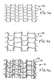
- Figs. 3a-3c illustrate schematically the manner in which an inventive alarm mat can be constructed, wherewith Fig. 3a is a schematic illustration of a base mat section;
- Fig. 3b is a schematic illustration of a supplementary mat section and
- Fig. 3c is a schematic illustration of a section of the complete alarm mat;
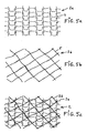
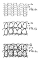
- Figs. 4a-4c to Figs. 7a-7c inclusive illustrate in a corresponding manner four further embodiments of inventive alarm mats;
- Fig. 8 is a perspective view of a transport container/security container constructed from inventive sheet elements;
- Fig. 9 is a cross-sectional view of one embodiment of an openable overlap join between the sheet elements of the container shown in Fig. 8.
- the sheet element 10 includes a first outer layer 1, an alarm mat 2, and a second outer layer 3 (see Figs. 1 and 2).
- the first outer layer 1 may consist of a glass fibre mat or a textile mat, although other types of mat, fabrics, materials, or panels may, of course, be used.
- the outer sheet 1 may alternatively consist of paint or a gel coating.
- the alarm mat 2 is designed to indicate or detect attempts to force holes in the sheet element 10.
- the alarm mat 2 includes a base mat 2a and a supplementary mat 2b.
- the base mat 2a is comprised of a fine-mesh filament mat that has been knitted, crocheted or woven, for instance.
- the material used in this respect is comprised of electrically conductive filaments 4 in the form of threads or ribbons made, e.g., of metal or electrically conductive plastic material.
- the threads 4 normally include an insulation layer and may comprise, for instance, a copper wire that is insulated with a layer of varnish of the kind commonly used in small electric motors. It can be mentioned by way of example that the filaments used may comprise varnished copper wire having a diameter of about 0.2 mm and given a mesh density or a mesh size of about 1 mm, although it will be understood that the invention is not restricted to this example. Optical fibres may also be used.
- a characteristic feature of the base mat 2a resides in its generally regular pattern, and in one particularly preferred embodiment the base mat has a looped pattern of the kind obtained when knitting or crocheting, for instance.
- looping patterns of different productions and design.
- a loop pattern or ring pattern in which electric current flows in mutually opposite directions in respective adjacent loops or rings are particularly beneficial from an attenuation aspect or damping aspect with respect to rapid damping/extinguishing of interferences and disturbances in an alarm-raising circuit generated, e.g., by magnetic fields, static electricity or radio waves and similar phenomena.
- Figs. 3a-7a illustrate different embodiments of the base mat 2a.
- Figs. 3a-6a show the base mat 2a in a knitted pattern, while Figure 7a shows the base mat 2a with a loop pattern of different design.
- the supplemental mat 2b may have either a regular or irregular pattern and shape.
- the supplemental mat 2b may, for instance, be a fine-mesh filament mat produced by knitting, crocheting or weaving.
- an electrically conductive filament 5 in the form of, e.g., a thread, wire or ribbon of, e.g., metal or an electrically conductive plastic material.
- the filaments 5 are normally provided with an insulating layer.
- copper wire that includes an insulating varnished layer of the type used in small electric motors.
- varnished copper wire that has a diameter of about 0.2 mm and a mesh density or mesh size of about 1 mm. It is also conceivable to use optical fibres.
- Fig. 3b illustrates a knitted supplemental mat 2b that has roughly the same filament dimensions and mesh size as the base mat 2a in Fig. 3a.
- Fig. 4b illustrates a knitted supplemental mat 2b whose mesh size is larger than the mesh size of the base mat 2a in Fig. 4a.
- the filament dimensions are roughly the same as the filament dimensions of the base mat 2a and of the supplemental mat 2b.
- the supplemental mat 2b may have a mesh size that is about 1.5-10 times larger than the mesh size of the base mat 2a.
- Fig. 5b illustrates an irregular supplemental mat 2b that can be integrated with the base mat 2a in Fig. 5a in several different ways.
- Fig. 6b illustrates a regular supplemental mat 2b of looped construction, although not knitted.
- Fig. 6a shows a knitted base mat 2a.
- the supplemental mat 2b shown in Fig. 7b may have any desired shape and construction.
- Fig. 7a shows a base mat 2a of loop construction.
- the supplemental mat 2b may be both regular or irregular with respect to its pattern and shape.
- the supplemental mat has a knitted or crocheted loop pattern.
- loop patterns other than knitted or crocheted patterns can be used.
- the loop or ring pattern in which mutually adjacent loops carry current in mutually opposite directions are particularly beneficial from the aspect rapidly damping/extinguishing interference generated in the alarm-raising circuit by magnetic fields, static electricity, radio waves or like phenomena, for instance.
- a supplemental mat 2b that has an irregular pattern and shape does not posses the same good interference damping properties as a mat of regular shape and pattern, its interference damping properties can nevertheless be accepted when used together with a base mat 2a, at least for some applications.
- the alarm mat 2 is thus comprised of a base mat-supplemental mat-combination, as shown by way of example in Figs. 3c-7c.
- Fig. 3c illustrates an alarm mat 2 which comprises the base mat 2a of Fig. 3a and a supplemental mat 2b of Fig. 3b superimposed on the base mat 2a.
- the base mat 2a and the supplemental mat 2b have, in this case, roughly the same pattern, shape and size and are tightly brought together or tightly pressed together to form the alarm mat 2.
- the supplemental mat 2b is displaced parallel with the base mat 2a such that the pattern resulting from the combined mats will be extremely bewildering and difficult to manipulate when the alarm mat 2 is included as an integrated layer in the complete sheet element or laminate 10.
- Fig. 4c illustrates an alarm mat 2 that comprises a combination of the base mat 2a shown in Fig. 4a and the supplemental mat 2b shown in Fig. 4b.
- Fig. 5c illustrates an alarm mat 2 that comprises a combination of the base mat 2a shown in Fig. 5a and the supplemental mat 2b shown in Fig. 5b.
- the supplemental mat 2b is either simply placed on the base mat 2a or is, e.g., sewn thereto.
- Fig. 6c illustrates an alarm mat 2 that comprises a combination of the base mat 2a shown in Fig. 6a and the supplemental mat 2b shown in Fig. 6b.
- Fig. 7c illustrates an alarm mat 2 that comprises a combination of the base mat 2a shown in Fig. 7a and the supplemental mat 2b shown in Fig. 7b. It will be understood that many variations and combinations are possible within the scope of the invention.
- a common feature of all embodiments of the alarm mat 2 resides in the complexity of the combined mat patterns that arrive from the tight combination or tight mutual compression of the base mat 2a and the supplemental mat 2b.
- the construction of the alarm mat 2 is particularly difficult to analyse when said mat constitutes a compressed layer in the finished, and normally opaque, sheet element 10.
- the alarm-thread-free surfaces of the sheet element will be smaller than if only a base mat is used instead of the inventive mat combination.
- inventive base mats and supplemental mats are possible within the scope of the inventive concept.
- the patterns, sizes and orientations of the base mats and supplemental mats can be varied and the mats can be joined together in many different ways as required. It may normally suffice to lay the mats tightly against one another or to press the mats into mutual abutment without bonding the mats one to the other, as the alarm mat is integrated in the sheet element.
- the base mat and/or the supplemental mat may comprise double filaments.
- the number of electric circuits in the alarm mat may, of course, be varied from one electric circuit to a plurality of circuits within the scope of the invention.
- the base mats and the supplemental mats may be connected in series or in parallel according to wishes and requirements, so as to obtain desired current flows in the alarm-raising circuit in question.
- the filaments in the base mat and/or in the supplemental mat need only be insulated at filament intersections or where filaments contact each other.
- the other mat need not include insulated filaments.
- the supplemental mat may be excluded from the alarm-raising circuit that the alarm mat, or security mat, is intended to include, or the base mat and the supplemental mat may be connected to mutual separate alarm-raising circuits and/or alarm-raising devices.
- the alarm mat or security mat
- the supplemental mat may be connected to mutual separate alarm-raising circuits and/or alarm-raising devices.
- the inventive alarm mat is very capable of resisting interferences emanating from electromagnetic force fields, static electricity, radio waves and like phenomena.
- an alarm-raising mat 2 such as its mesh density, the number of electric circuits included, its flexibility, etc., constitutes control factors in the choice of the manufacturing method applied.
- One or more electric signals is/are sent through the alarm mat 2 and in the event of an attempt to force a hole in the sheet element 10 being made, the electric signal in the mat is broken as a result of a filament breakage, therewith triggering an alarm.
- the same will apply to light signals when optical fibres are used.
- the other surface layer 3 is suitably constructed in the same manner or in a similar manner to the first outer layer 1.
- the second surface layer 3 may consist of a thin layer of varnish.
- the sheet element 10 is applied so that the surface layer 1 forms the exterior of the container/space and the surface layer 3 is proximal to the container interior, and consequently the surface layers may vary with respect to finish and construction.
- the layers 1-3 are joined together, for instance, by means of a gluing, injection, or pressing process.
- a number of different binding agents can be used in this regard, such as polyester resin or other resins, for instance, therewith enabling a stable sheet element to be formed.
- the sheet element may be given a number of different shapes in addition to a planar fundamental shape, wherewith a security container or security bag consisting solely of two curved laminate parts that overlap each other in the joint region of said parts can be produced.
- Fig. 8 shows an example of a transport container or case 20 constructed in this way.
- the case 20 illustrated in Fig. 8 is thus comprised of two specially shaped inventive sheet element parts 10a and 10b, wherewith said sheet element parts are configured so that when the case is closed they will be brought together in an overlap zone 21 with the smallest possible gap 22 therebetween.
- the case 20 is conveniently provided with a handle 23 glued on the outside of the case, and with glued-on hinges and locking devices, etc., such that no holes are present in the sheet element parts.
- a number of contact devices or detection devices 24,25 are disposed immediately inwards of the overlapping part 21, said devices 24 being carried by a strip 26 glued to the sheet element part 10a, and the devices 25 being carried by a strip 27 glued to the sheet element part 10b.
- the strips 26 and 27 will preferably extend around the whole of the case perimeter and will carry an appropriate number of contact devices 24,25.
- the alarm mats 2 of the sheet elements 10a and 10b form a security cage and the contact devices 24 and 25 are interconnected so as to be included in one or more signal current circuits.
- the signal current circuits break when an attempt to force a hole in the case breaks a filament 4,5 in the alarm mat 2.
- the alarm mat 2 is present everywhere around the entire surface of the case or container 20. Naturally, there will be an alarm mat overlap at part 21.
- the signal current circuit will also be broken if an attempt is made to bend the gap 22 apart, in an attempt to obtain access to the case interior, wherewith breaking of the electric circuit breaks the electric contact between the devices 24 and 25 by virtue of a change in the distance between said devices in conjunction with this bending action.
- an electronic unit Arranged inside the transport container or case 20 is an electronic unit and, e.g., one or more ampoules or cartridges that contain a destructive agent, for instance dye containing cartridges.
- the electronic unit is adapted to activate the destructive cartridges immediately the signal current circuit is broken, so as to destroy the valuable contents of the container 20.
- Activation and deactivation of the alarm system/the electronic unit is effected by some appropriate code system that has a high security level.
- the container will, of course, also contain an electric power source. In this regard, it is also possible to pre-set a time at which the destructive agent will be triggered, with the intention of introducing a further stress factor for potential criminals.
- the inventive alarm mat 2 also functions as a particularly effective means of protection against external interferences from, e.g., different types of magnetic fields and electrostatic fields, radio waves and similar phenomena, as a result of dampening voltage or interferences caused by these phenomena so rapidly that the reaction time of the electronic unit can be given a time duration that is so short that there will be no time to disarm the destructive agent before it is activated, even by firing a bullet from a high velocity weapon directly onto the activation means of the destructive element. Because of this extremely rapid interference dampening effect, the risk of the destructive agent being triggered as a result of a false alarm due to external interference is reduced.
- the inventive alarm mat 2 thus highly effective prevents interferences and disturbances on, e.g., electronic and computer equipment contained inside the container 20 comprised of the sheet elements 10.
- the aforedescribed case or container 20 is thus extremely suitable for use in transporting different kinds of valuable objects.
- the inventive sheet elements 10 can thus be used in the construction of containers, rooms or other mobile or permanent spaces where it is desired to prevent access by e.g. forcing holes in the structure. If an attempt to force a hole is made, some form of destructive agent will be activated so as to render the material stored in the space worthless or unusable, or will result in the activation of an alarm.
- An overlapping drilling guard is provided at joins and doors, and contacts that function to break a signal circuit if an attempt to bend away material is made are disposed inwardly of the joins. These contacts are suitably connected in series with the alarm mats, so as to keep down the number of electric circuits.
- inventive sheet element can be used in e.g. cases, bags, or other containers for the transportation of valuable objects, such as money transportation, security containers for motor vehicles and aircraft, weapon storage facilities, inexpensive bank vaults, etc.
- the sheet element may consist of solely one alarm mat and one outer layer, provided that bonding of the alarm mat to the outer layer is sufficiently effective.
- the sheet element may alternatively include additional layers of different kinds if so desired. Material selection may, of course, also be varied. A thickness of about 2-5 mm is an example of suitable sheet element thickness, although said sheets are not restricted to such thicknesses.
- the sheet element will most often be opaque, for obvious reasons.
- the alarm mat may suitably be baked or cast in the sheet element, or firmly glued thereto.
- the sheet element may include stiffening means. The alarm mat is normally continuous and covers the entire sheet element.
- the base mat 2a and the supplemental mat 2b are comprised of filaments that have mutually different melting points.
- the base mat 2a may be comprised of a copper wire and the supplemental mat 2b comprised of a metal wire that has a relatively low melting point in comparison with the melting point of the copper wires. If an attempt is made to penetrate the sheet element without triggering an alarm by heating or some other temperature raising manipulation, the wires in the supplemental mat will melt first and therewith initiate an alarm. If desired, the melting point of the wire in the base mat can of course be lower than the melting point of the wire in the supplemental mat.
- varying pulse trains may be sent in the base mat and the supplemental mat for creating confusion. This further enhances the problems associated with attempts to manipulate the system.
- the construction of the alarm mat in said elements can be varied continuously with the intention of causing confusion, even within the same product or product program. These variation possibilities make mapping of the alarm mat construction impossible and therewith provide an extraordinarily high security level.
Landscapes
- Burglar Alarm Systems (AREA)
- Pens And Brushes (AREA)
- Electrochromic Elements, Electrophoresis, Or Variable Reflection Or Absorption Elements (AREA)
- Devices For Indicating Variable Information By Combining Individual Elements (AREA)
- Materials For Medical Uses (AREA)
- Preparing Plates And Mask In Photomechanical Process (AREA)
- Semiconductor Memories (AREA)
Applications Claiming Priority (3)
| Application Number | Priority Date | Filing Date | Title |
|---|---|---|---|
| SE0002841A SE523393C2 (sv) | 2000-08-08 | 2000-08-08 | Skivelement med integrerad larmmatta samt användning och förfarande för framställning av ett sådant skivelement |
| SE0002841 | 2000-08-08 | ||
| PCT/SE2001/001720 WO2002012671A1 (en) | 2000-08-08 | 2001-08-07 | A sheet element and its use |
Publications (2)
| Publication Number | Publication Date |
|---|---|
| EP1309768A1 EP1309768A1 (en) | 2003-05-14 |
| EP1309768B1 true EP1309768B1 (en) | 2007-05-02 |
Family
ID=20280640
Family Applications (1)
| Application Number | Title | Priority Date | Filing Date |
|---|---|---|---|
| EP01961496A Expired - Lifetime EP1309768B1 (en) | 2000-08-08 | 2001-08-07 | A sheet element and its use |
Country Status (15)
| Country | Link |
|---|---|
| US (1) | US6755050B2 (pl) |
| EP (1) | EP1309768B1 (pl) |
| JP (1) | JP4834280B2 (pl) |
| CN (1) | CN1222674C (pl) |
| AT (1) | ATE361411T1 (pl) |
| AU (2) | AU8275801A (pl) |
| DE (1) | DE60128236T2 (pl) |
| DK (1) | DK1309768T3 (pl) |
| EE (1) | EE04887B1 (pl) |
| ES (1) | ES2288170T3 (pl) |
| MX (1) | MXPA03001197A (pl) |
| PL (1) | PL203079B1 (pl) |
| SE (1) | SE523393C2 (pl) |
| WO (1) | WO2002012671A1 (pl) |
| ZA (1) | ZA200300985B (pl) |
Families Citing this family (7)
| Publication number | Priority date | Publication date | Assignee | Title |
|---|---|---|---|---|
| DE10241709B4 (de) * | 2002-09-09 | 2007-01-11 | Fraunhofer-Gesellschaft zur Förderung der angewandten Forschung e.V. | Sicherungsverbundsystem |
| KR100778623B1 (ko) * | 2003-01-14 | 2007-11-22 | 유나이티드 테크놀로지스 코포레이션 | 선적 컨테이너 및 그 사용 방법 |
| US6854296B1 (en) * | 2004-01-23 | 2005-02-15 | Sara Lee Corporation | Bi-ply fabric construction and apparel formed therefrom |
| CN101130401B (zh) * | 2006-08-21 | 2010-05-12 | 中国国际海运集装箱(集团)股份有限公司 | 安全装置及其集装箱,以及提高集装箱安全性的方法 |
| US20080142692A1 (en) * | 2006-12-18 | 2008-06-19 | Lee Lanny R | Intelligent tripwire system |
| US20170102217A1 (en) * | 2015-10-13 | 2017-04-13 | Amos Golan | Early warning projectile penetration system |
| EP4092641B1 (de) | 2021-05-20 | 2024-08-21 | Schmitz Cargobull AG | Kofferaufbau für ein nutzfahrzeug und verfahren zur herstellung eines flächenelements für einen solchen kofferaufbau |
Family Cites Families (9)
| Publication number | Priority date | Publication date | Assignee | Title |
|---|---|---|---|---|
| US362010A (en) * | 1887-04-26 | Electric covering for indicating abnormal conditions | ||
| US708093A (en) * | 1901-05-25 | 1902-09-02 | Henry M Sutton | Electrically-protected structure. |
| US3696373A (en) * | 1970-08-12 | 1972-10-03 | John Malcolm Dunn | Electric alarm screen |
| GB9209368D0 (en) * | 1992-04-30 | 1992-06-17 | Wolf Adrian F | A method of making a flexible closure incorporating an alarm system |
| SE501675C2 (sv) * | 1992-05-10 | 1995-04-10 | Kjell Lindskog | Laminatskiva och användning av dylik |
| US6215397B1 (en) * | 1996-08-13 | 2001-04-10 | Lindskog Innovation Ab | Electrical manually portable security case for the storage of theft attractive articles with an electrical mat having at least one elongated electrically conductive wire in a substantially continuous mesh, loop or eye structure |
| US5592149A (en) * | 1992-07-21 | 1997-01-07 | Alizi; Uri | Security fence |
| GB2270785B (en) * | 1992-09-22 | 1996-05-08 | Gore & Ass | Improvements in security enclosure manufacture |
| SE9302390D0 (sv) | 1993-07-12 | 1993-07-12 | Kjell Jaegerskog | Portabel saekerhetsbehaallare |
-
2000
- 2000-08-08 SE SE0002841A patent/SE523393C2/sv not_active IP Right Cessation
-
2001
- 2001-08-07 MX MXPA03001197A patent/MXPA03001197A/es active IP Right Grant
- 2001-08-07 JP JP2002517934A patent/JP4834280B2/ja not_active Expired - Fee Related
- 2001-08-07 EE EEP200300056A patent/EE04887B1/xx not_active IP Right Cessation
- 2001-08-07 ES ES01961496T patent/ES2288170T3/es not_active Expired - Lifetime
- 2001-08-07 WO PCT/SE2001/001720 patent/WO2002012671A1/en not_active Ceased
- 2001-08-07 AU AU8275801A patent/AU8275801A/xx active Pending
- 2001-08-07 AU AU2001282758A patent/AU2001282758B2/en not_active Ceased
- 2001-08-07 PL PL360114A patent/PL203079B1/pl unknown
- 2001-08-07 DE DE60128236T patent/DE60128236T2/de not_active Expired - Lifetime
- 2001-08-07 US US10/344,025 patent/US6755050B2/en not_active Expired - Fee Related
- 2001-08-07 AT AT01961496T patent/ATE361411T1/de not_active IP Right Cessation
- 2001-08-07 CN CNB018153119A patent/CN1222674C/zh not_active Expired - Fee Related
- 2001-08-07 DK DK01961496T patent/DK1309768T3/da active
- 2001-08-07 EP EP01961496A patent/EP1309768B1/en not_active Expired - Lifetime
-
2003
- 2003-02-05 ZA ZA200300985A patent/ZA200300985B/en unknown
Also Published As
| Publication number | Publication date |
|---|---|
| WO2002012671A1 (en) | 2002-02-14 |
| PL203079B1 (pl) | 2009-08-31 |
| US6755050B2 (en) | 2004-06-29 |
| ATE361411T1 (de) | 2007-05-15 |
| JP2004506111A (ja) | 2004-02-26 |
| CN1222674C (zh) | 2005-10-12 |
| MXPA03001197A (es) | 2003-10-06 |
| ZA200300985B (en) | 2003-08-05 |
| PL360114A1 (pl) | 2004-09-06 |
| ES2288170T3 (es) | 2008-01-01 |
| DE60128236D1 (de) | 2007-06-14 |
| EP1309768A1 (en) | 2003-05-14 |
| EE04887B1 (et) | 2007-08-15 |
| AU2001282758B2 (en) | 2007-08-09 |
| JP4834280B2 (ja) | 2011-12-14 |
| DE60128236T2 (de) | 2008-01-03 |
| SE523393C2 (sv) | 2004-04-13 |
| AU8275801A (en) | 2002-02-18 |
| DK1309768T3 (da) | 2007-09-17 |
| SE0002841L (sv) | 2002-02-09 |
| AU2001282758B8 (en) | 2002-02-18 |
| EE200300056A (et) | 2004-12-15 |
| US20030194530A1 (en) | 2003-10-16 |
| SE0002841D0 (sv) | 2000-08-08 |
| CN1452683A (zh) | 2003-10-29 |
Similar Documents
| Publication | Publication Date | Title |
|---|---|---|
| EP0725881B1 (en) | Laminate and use of the same | |
| US6215397B1 (en) | Electrical manually portable security case for the storage of theft attractive articles with an electrical mat having at least one elongated electrically conductive wire in a substantially continuous mesh, loop or eye structure | |
| EP1309768B1 (en) | A sheet element and its use | |
| CN103249327A (zh) | 安全包装装置 | |
| US7646299B2 (en) | Anti-tampering security material | |
| AU2001282758A1 (en) | A sheet element and its use | |
| WO1995002742A1 (en) | Portable safety box | |
| EP1481145B1 (en) | Method and device related to a container | |
| CA2262573C (en) | Electronic anti-theft element | |
| CA2262585C (en) | Resonant circuit for electronic anti-theft element | |
| CA2135162C (en) | Electrical manually portable security case for the storage of theft attractive articles with an electrical mat | |
| SE501674C2 (sv) | Skivelement och användning av dylik |
Legal Events
| Date | Code | Title | Description |
|---|---|---|---|
| PUAI | Public reference made under article 153(3) epc to a published international application that has entered the european phase |
Free format text: ORIGINAL CODE: 0009012 |
|
| 17P | Request for examination filed |
Effective date: 20030306 |
|
| AK | Designated contracting states |
Designated state(s): AT BE CH CY DE DK ES FI FR GB GR IE IT LI LU MC NL PT SE TR |
|
| AX | Request for extension of the european patent |
Extension state: AL LT LV MK RO SI |
|
| 17Q | First examination report despatched |
Effective date: 20050404 |
|
| GRAP | Despatch of communication of intention to grant a patent |
Free format text: ORIGINAL CODE: EPIDOSNIGR1 |
|
| RIN1 | Information on inventor provided before grant (corrected) |
Inventor name: LINDSKOG, KJELL |
|
| GRAS | Grant fee paid |
Free format text: ORIGINAL CODE: EPIDOSNIGR3 |
|
| GRAA | (expected) grant |
Free format text: ORIGINAL CODE: 0009210 |
|
| AK | Designated contracting states |
Kind code of ref document: B1 Designated state(s): AT BE CH CY DE DK ES FI FR GB GR IE IT LI LU MC NL PT SE TR |
|
| AX | Request for extension of the european patent |
Extension state: LT LV |
|
| PG25 | Lapsed in a contracting state [announced via postgrant information from national office to epo] |
Ref country code: FI Free format text: LAPSE BECAUSE OF FAILURE TO SUBMIT A TRANSLATION OF THE DESCRIPTION OR TO PAY THE FEE WITHIN THE PRESCRIBED TIME-LIMIT Effective date: 20070502 |
|
| REG | Reference to a national code |
Ref country code: GB Ref legal event code: FG4D |
|
| REG | Reference to a national code |
Ref country code: CH Ref legal event code: EP |
|
| REG | Reference to a national code |
Ref country code: IE Ref legal event code: FG4D |
|
| REF | Corresponds to: |
Ref document number: 60128236 Country of ref document: DE Date of ref document: 20070614 Kind code of ref document: P |
|
| PG25 | Lapsed in a contracting state [announced via postgrant information from national office to epo] |
Ref country code: SE Free format text: LAPSE BECAUSE OF FAILURE TO SUBMIT A TRANSLATION OF THE DESCRIPTION OR TO PAY THE FEE WITHIN THE PRESCRIBED TIME-LIMIT Effective date: 20070802 |
|
| REG | Reference to a national code |
Ref country code: DK Ref legal event code: T3 |
|
| REG | Reference to a national code |
Ref country code: CH Ref legal event code: NV Representative=s name: AMMANN PATENTANWAELTE AG BERN |
|
| LTIE | Lt: invalidation of european patent or patent extension |
Effective date: 20070502 |
|
| NLV1 | Nl: lapsed or annulled due to failure to fulfill the requirements of art. 29p and 29m of the patents act | ||
| ET | Fr: translation filed | ||
| PG25 | Lapsed in a contracting state [announced via postgrant information from national office to epo] |
Ref country code: AT Free format text: LAPSE BECAUSE OF FAILURE TO SUBMIT A TRANSLATION OF THE DESCRIPTION OR TO PAY THE FEE WITHIN THE PRESCRIBED TIME-LIMIT Effective date: 20070502 |
|
| REG | Reference to a national code |
Ref country code: ES Ref legal event code: FG2A Ref document number: 2288170 Country of ref document: ES Kind code of ref document: T3 |
|
| PG25 | Lapsed in a contracting state [announced via postgrant information from national office to epo] |
Ref country code: PT Free format text: LAPSE BECAUSE OF FAILURE TO SUBMIT A TRANSLATION OF THE DESCRIPTION OR TO PAY THE FEE WITHIN THE PRESCRIBED TIME-LIMIT Effective date: 20071002 Ref country code: NL Free format text: LAPSE BECAUSE OF FAILURE TO SUBMIT A TRANSLATION OF THE DESCRIPTION OR TO PAY THE FEE WITHIN THE PRESCRIBED TIME-LIMIT Effective date: 20070502 |
|
| PLBE | No opposition filed within time limit |
Free format text: ORIGINAL CODE: 0009261 |
|
| STAA | Information on the status of an ep patent application or granted ep patent |
Free format text: STATUS: NO OPPOSITION FILED WITHIN TIME LIMIT |
|
| 26N | No opposition filed |
Effective date: 20080205 |
|
| PG25 | Lapsed in a contracting state [announced via postgrant information from national office to epo] |
Ref country code: MC Free format text: LAPSE BECAUSE OF NON-PAYMENT OF DUE FEES Effective date: 20070831 Ref country code: GR Free format text: LAPSE BECAUSE OF FAILURE TO SUBMIT A TRANSLATION OF THE DESCRIPTION OR TO PAY THE FEE WITHIN THE PRESCRIBED TIME-LIMIT Effective date: 20070803 |
|
| PG25 | Lapsed in a contracting state [announced via postgrant information from national office to epo] |
Ref country code: IE Free format text: LAPSE BECAUSE OF NON-PAYMENT OF DUE FEES Effective date: 20070807 |
|
| PG25 | Lapsed in a contracting state [announced via postgrant information from national office to epo] |
Ref country code: CY Free format text: LAPSE BECAUSE OF FAILURE TO SUBMIT A TRANSLATION OF THE DESCRIPTION OR TO PAY THE FEE WITHIN THE PRESCRIBED TIME-LIMIT Effective date: 20070502 |
|
| PG25 | Lapsed in a contracting state [announced via postgrant information from national office to epo] |
Ref country code: LU Free format text: LAPSE BECAUSE OF NON-PAYMENT OF DUE FEES Effective date: 20070807 |
|
| PG25 | Lapsed in a contracting state [announced via postgrant information from national office to epo] |
Ref country code: TR Free format text: LAPSE BECAUSE OF FAILURE TO SUBMIT A TRANSLATION OF THE DESCRIPTION OR TO PAY THE FEE WITHIN THE PRESCRIBED TIME-LIMIT Effective date: 20070502 |
|
| PGFP | Annual fee paid to national office [announced via postgrant information from national office to epo] |
Ref country code: CH Payment date: 20140818 Year of fee payment: 14 Ref country code: DK Payment date: 20140819 Year of fee payment: 14 Ref country code: DE Payment date: 20140801 Year of fee payment: 14 |
|
| PGFP | Annual fee paid to national office [announced via postgrant information from national office to epo] |
Ref country code: ES Payment date: 20140812 Year of fee payment: 14 Ref country code: FR Payment date: 20140901 Year of fee payment: 14 Ref country code: GB Payment date: 20140827 Year of fee payment: 14 |
|
| PGFP | Annual fee paid to national office [announced via postgrant information from national office to epo] |
Ref country code: IT Payment date: 20140808 Year of fee payment: 14 |
|
| PGFP | Annual fee paid to national office [announced via postgrant information from national office to epo] |
Ref country code: BE Payment date: 20140826 Year of fee payment: 14 |
|
| REG | Reference to a national code |
Ref country code: DE Ref legal event code: R119 Ref document number: 60128236 Country of ref document: DE |
|
| REG | Reference to a national code |
Ref country code: DK Ref legal event code: EBP Effective date: 20150831 |
|
| REG | Reference to a national code |
Ref country code: CH Ref legal event code: PL |
|
| GBPC | Gb: european patent ceased through non-payment of renewal fee |
Effective date: 20150807 |
|
| PG25 | Lapsed in a contracting state [announced via postgrant information from national office to epo] |
Ref country code: IT Free format text: LAPSE BECAUSE OF NON-PAYMENT OF DUE FEES Effective date: 20150807 Ref country code: LI Free format text: LAPSE BECAUSE OF NON-PAYMENT OF DUE FEES Effective date: 20150831 Ref country code: CH Free format text: LAPSE BECAUSE OF NON-PAYMENT OF DUE FEES Effective date: 20150831 |
|
| REG | Reference to a national code |
Ref country code: FR Ref legal event code: ST Effective date: 20160429 |
|
| PG25 | Lapsed in a contracting state [announced via postgrant information from national office to epo] |
Ref country code: GB Free format text: LAPSE BECAUSE OF NON-PAYMENT OF DUE FEES Effective date: 20150807 Ref country code: DE Free format text: LAPSE BECAUSE OF NON-PAYMENT OF DUE FEES Effective date: 20160301 |
|
| PG25 | Lapsed in a contracting state [announced via postgrant information from national office to epo] |
Ref country code: DK Free format text: LAPSE BECAUSE OF NON-PAYMENT OF DUE FEES Effective date: 20150831 Ref country code: FR Free format text: LAPSE BECAUSE OF NON-PAYMENT OF DUE FEES Effective date: 20150831 |
|
| REG | Reference to a national code |
Ref country code: ES Ref legal event code: FD2A Effective date: 20160927 |
|
| PG25 | Lapsed in a contracting state [announced via postgrant information from national office to epo] |
Ref country code: ES Free format text: LAPSE BECAUSE OF NON-PAYMENT OF DUE FEES Effective date: 20150808 |
|
| PG25 | Lapsed in a contracting state [announced via postgrant information from national office to epo] |
Ref country code: BE Free format text: LAPSE BECAUSE OF NON-PAYMENT OF DUE FEES Effective date: 20150831 |