EP1309237A2 - Türeinrichtung für abgeschirmte Schränke - Google Patents
Türeinrichtung für abgeschirmte Schränke Download PDFInfo
- Publication number
- EP1309237A2 EP1309237A2 EP02257432A EP02257432A EP1309237A2 EP 1309237 A2 EP1309237 A2 EP 1309237A2 EP 02257432 A EP02257432 A EP 02257432A EP 02257432 A EP02257432 A EP 02257432A EP 1309237 A2 EP1309237 A2 EP 1309237A2
- Authority
- EP
- European Patent Office
- Prior art keywords
- door
- coupled
- enclosure
- axis gimbal
- seal
- Prior art date
- Legal status (The legal status is an assumption and is not a legal conclusion. Google has not performed a legal analysis and makes no representation as to the accuracy of the status listed.)
- Withdrawn
Links
- 230000006835 compression Effects 0.000 claims abstract description 21
- 238000007906 compression Methods 0.000 claims abstract description 21
- 238000000034 method Methods 0.000 claims abstract description 8
- 230000007246 mechanism Effects 0.000 claims description 12
- 238000006073 displacement reaction Methods 0.000 claims description 2
- 238000007789 sealing Methods 0.000 abstract description 7
- 238000002955 isolation Methods 0.000 abstract description 6
- 238000013459 approach Methods 0.000 description 6
- 230000013011 mating Effects 0.000 description 5
- 230000005855 radiation Effects 0.000 description 4
- 238000013461 design Methods 0.000 description 3
- 238000003754 machining Methods 0.000 description 3
- 238000004519 manufacturing process Methods 0.000 description 3
- 230000004913 activation Effects 0.000 description 2
- 238000012986 modification Methods 0.000 description 2
- 230000004048 modification Effects 0.000 description 2
- 238000012360 testing method Methods 0.000 description 2
- 230000009849 deactivation Effects 0.000 description 1
- 230000001419 dependent effect Effects 0.000 description 1
- 238000010586 diagram Methods 0.000 description 1
- 239000013013 elastic material Substances 0.000 description 1
- 238000003780 insertion Methods 0.000 description 1
- 230000037431 insertion Effects 0.000 description 1
- 230000003993 interaction Effects 0.000 description 1
- 230000008520 organization Effects 0.000 description 1
Images



Classifications
-
- H—ELECTRICITY
- H05—ELECTRIC TECHNIQUES NOT OTHERWISE PROVIDED FOR
- H05K—PRINTED CIRCUITS; CASINGS OR CONSTRUCTIONAL DETAILS OF ELECTRIC APPARATUS; MANUFACTURE OF ASSEMBLAGES OF ELECTRICAL COMPONENTS
- H05K9/00—Screening of apparatus or components against electric or magnetic fields
- H05K9/0007—Casings
- H05K9/0015—Gaskets or seals
Definitions
- This invention relates generally to the field of radio frequency (RF) shielding systems, and more specifically to the design of door systems for RF enclosures, in particular a floating door system.
- RF radio frequency
- RF sealing is employed in test and production environments where the amount of radiation emitted or absorbed by an electronic device must be closely controlled. Excess RF exposure can lead to erroneous test results, or in production and operational environments, degrade the performance of equipment sensitive to the emitted radiation. RF sealing is also important when an electronic component emits sufficient radiation to impact the performance of other proximate electronic components. In this second case, RF sealing isolates the source of radiation, while the first case may be used to isolate sensitive RF components.
- RF sealing requires close attention wherever an opening is required.
- RF seals that are dependent on compressed gaskets perform relative to the amount of compression on the gasket.
- an active opening such as a door-RF enclosure interface, that employs a similar seal, induces additional design difficulties in order to achieve uniform seal compression.
- the compression uniformity must extend around the entire length of the seal.
- the compression of the gasket induces reactive forces that cause elastic materials to deflect. The reactive deflection of components causes non-uniformity in the gaskets compression and as a result degrades the RF seal quality.
- the drawer door must be rigid enough to support a load and ensure a uniform seal across the length of the door-enclosure interface.
- One technique to address this rigidity requirement is to use precision machining and rigidity of mating components. This approach is costly, due to the price of precision machining.
- Other systems accept an RF seal with non-uniform compression in order to save the expenses associated with the precision machining. However, non-uniform compression results in non-uniform RF isolation.
- the drawer door must be rigid enough to withstand loads along the axis of the drawer door as well as perpendicular to the door axis.
- drawer door RF seal systems do not generally employ a gimbal system on the door.
- the use of a gimbal system allows the door to "float" on one or more axes.
- User feedback of a floating door exposes a perceived lack of rigidity and associated poor quality.
- the floating drawer door system of the present invention establishes structural stability through the use of three points of contact between the drawer door and the drawer base, whenever the drawer door is not engaged with the sealing portion of the associated frame. As the door approaches the frame, two of the three contact points are deactivated, allowing the drawer the freedom to pivot from a point near the seal centroid.
- a pivoting gimbal system provides the primary contact point. By using the gimbal, employing two-axes of rotation, rotation, in the third axis is restricted.
- Two spring plungers are employed, referencing into conical detents, to provide the remaining two contact points. The implementation of the spring plungers is twofold. Retracting the plungers from the detents allows the drawer door gimbal to apply the closing force at the centroid of the gasket interaction line.
- a pin is employed to apply a force against the nose of the plunger.
- the pin is displaced by a trigger mechanism.
- the trigger is displaced as it contacts a dowel pin installed in the frame.
- the dowel pin is strategically positioned such that it cams the trigger just as the door approaches its mating surface.
- One activation pin, one dowel pin, and one trigger are employed for each of the two spring plungers according to an embodiment of the present invention.
- the release of two of the three contact points allows the drawer door to float in order to utilize the functionality of the two-axis gimbal system.
- This floating system allows the mating surfaces to be parallel and not deflect as the forces resulting from gasket compression are applied. To help achieve this, the mating force is applied to the centroid of the force line.
- the gimbal prevents distortion due to off-center loading, by its location at the centroid through which the load is applied.
- the floating gimbal system also allows the door to float in order to maintain force uniformity as the compression seal is applied.
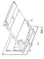
- Floating door system 100 comprises a drawer door 140 coupled to RF seal 150.
- RF seal 150 is the interface to RF enclosure 110 for providing uniform RF isolation.
- RF seal 150 is coupled to a two-axis gimbal 120.
- the two-axis gimbal 120 provides freedom in a horizontal direction and a vertical direction with respect to RF enclosure 110 to ensure uniform seal compression.
- the two-axis gimbal could also incorporate a third rotational axis. This third axis could be applied, for example, when the RF seal 150 is circular.
- Two-axis gimbal 120 is coupled to drawer frame 130.
- Drawer door 140 is also coupled to drawer frame 130.
- the drawer frame 130 provides stability and support for floating door system 100, and has points of insertion within the RF enclosure 110.
- Two-axis gimbal 120 contains a base 230 that provides the points of attachment to drawer frame 130.
- Base 230 provides stability for the two-axis gimbal system 120 and distributes the load of the two-axis gimbal 120 across drawer frame 130.
- Two-axis gimbal 120 also contains two horizontal pivot points 210 and one vertical pivot point 215. Pivot points 210 allow for motion with respect to a horizontal axis, while pivot point 215 allows for motion with respect to a vertical axis. Each of the three pivot points 210 and 215 are coupled to drawer mounting bar 220. Drawer mounting bar 220 provides a base of support for the pivot points and also provides a point of attachment for drawer door 140.
- Drawer engagement components 300 ensure that as the floating door system 100 contacts the RF enclosure 110, door 140 is able to move with two degrees of freedom. These degrees of freedom are provided by the two-axis gimbal 120.
- spring plunger release pin actuating triggers 310 contact dowel pins 320 installed in RF enclosure 110.
- the dowel pins 320 are located such that the spring plunger releaser pin actuating triggers 310 are cammed just as door 140 approaches a mating surface of RF enclosure 110. Displacement of spring plunger releaser pin actuating triggers 310 cause actuating pins to apply a force against the nose of spring plungers 330.
- Spring plungers 330 are then retracted so that two-axis gimbal 120 is operable to move with two degrees of freedom.
- one activation pin, one dowel pin, and one trigger are used for each of two spring plungers.
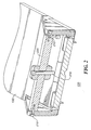
- FIG. 4 a cross sectional view of the gimbal lock mechanism 400 is shown.
- spring plunger release pin 410 is coupled to hollow spring plunger detent 420.
- Spring plunger 430 is also coupled to hollow spring plunger detent 420, so that spring plunger 430 lies in the conical hollow of spring plunger detent 420.
- FIG. 5 a method of engaging the RF seal between floating door system 100 and RF enclosure 110 is shown.
- block 510 it is assumed that drawer door 140 is coupled to drawer base 130 at three points, so that the RF seal is not engaged.
- two of the three contact points may be deactivated (block 520). This deactivation occurs when a trigger 310 is displaced as it contacts a dowel pin installed in door frame 150 (block 530).
- Trigger 310 actuation causes spring plunger release pin 410 to be displaced (block 540).
- spring plunger release pin 410 applies a force against nose of plunger of two spring plungers 430 in contact with drawer base 130 through hollow spring plunger detents 420 (block 550).
- Two spring plungers 430 are retracted, so that the only contact point between drawer door 140 and drawer base 130 is interface between drawer door 140 and two-axis gimbal 120 (block 560).
- Drawer door 140 is now able to pivot from a point near seal centroid using two-axis gimbal 120 (block 570).
- two-axis gimbal 120 allows uniform force across length of seal, so that seal compression is uniform (block 580).
- Uniform seal compression implies uniform RF isolation (block 590) when drawer door 140 is closed.
Landscapes
- Engineering & Computer Science (AREA)
- Microelectronics & Electronic Packaging (AREA)
- Casings For Electric Apparatus (AREA)
Applications Claiming Priority (2)
| Application Number | Priority Date | Filing Date | Title |
|---|---|---|---|
| US10/001,629 US6621001B2 (en) | 2001-10-31 | 2001-10-31 | Floating door system for RF enclosures |
| US1629 | 2001-10-31 |
Publications (2)
| Publication Number | Publication Date |
|---|---|
| EP1309237A2 true EP1309237A2 (de) | 2003-05-07 |
| EP1309237A3 EP1309237A3 (de) | 2004-12-22 |
Family
ID=21697050
Family Applications (1)
| Application Number | Title | Priority Date | Filing Date |
|---|---|---|---|
| EP02257432A Withdrawn EP1309237A3 (de) | 2001-10-31 | 2002-10-25 | Türeinrichtung für abgeschirmte Schränke |
Country Status (4)
| Country | Link |
|---|---|
| US (1) | US6621001B2 (de) |
| EP (1) | EP1309237A3 (de) |
| KR (1) | KR20030036023A (de) |
| TW (1) | TW580852B (de) |
Family Cites Families (3)
| Publication number | Priority date | Publication date | Assignee | Title |
|---|---|---|---|---|
| US5134547A (en) * | 1989-02-11 | 1992-07-28 | Olympus Optical Co., Ltd. | Electric apparatus housing an electromagnetic wave noise generating source |
| US5223670A (en) * | 1991-12-02 | 1993-06-29 | Her Majesty The Queen In Right Of Canada | Hinged door assembly |
| US6395976B1 (en) * | 1998-08-31 | 2002-05-28 | 3Com Corporation | Apparatus and method for aligning a circuit board assembly in an electronic chassis |
-
2001
- 2001-10-31 US US10/001,629 patent/US6621001B2/en not_active Expired - Fee Related
-
2002
- 2002-08-08 TW TW091117922A patent/TW580852B/zh not_active IP Right Cessation
- 2002-10-25 EP EP02257432A patent/EP1309237A3/de not_active Withdrawn
- 2002-10-30 KR KR1020020066361A patent/KR20030036023A/ko not_active Withdrawn
Also Published As
| Publication number | Publication date |
|---|---|
| US20030079892A1 (en) | 2003-05-01 |
| EP1309237A3 (de) | 2004-12-22 |
| TW580852B (en) | 2004-03-21 |
| US6621001B2 (en) | 2003-09-16 |
| KR20030036023A (ko) | 2003-05-09 |
Similar Documents
| Publication | Publication Date | Title |
|---|---|---|
| US20060198094A1 (en) | Data processing device | |
| KR100252249B1 (ko) | 컴퓨터 시스템 | |
| US20130104339A1 (en) | Movement assist device | |
| EP1545099A1 (de) | Verfahren und Vorrichtung für ein verschiebbares Funkkommunikationsendgerät | |
| US6309037B2 (en) | PCI I/O bracket retainer | |
| US6386719B1 (en) | Precision mounting of front surface mirrors | |
| US6621001B2 (en) | Floating door system for RF enclosures | |
| US20150041297A1 (en) | Button device of automatic vending machine | |
| EP2869678B1 (de) | Montagestruktur für elektrische vorrichtung | |
| US20130279974A1 (en) | Mounting assembly with locking mechanism | |
| US9672997B2 (en) | Method for the initial adjustment of a control device for electronic equipment | |
| JP2004207722A (ja) | 電磁シールド・アセンブリ | |
| CN220379292U (zh) | 一种固定支架及转接装置 | |
| CN107872939A (zh) | 用于机架的滑轨安装配件总成 | |
| JP2011193048A (ja) | ばねユニット及びスライド機構 | |
| US20260136485A1 (en) | Electronic device port ejection structure | |
| CN109388202B (zh) | 固定架组件 | |
| US20040242037A1 (en) | Top plate release mechanism | |
| US8418985B2 (en) | Electronic device frame and support mechanism utilized thereby | |
| CN210606424U (zh) | 显示屏 | |
| US5496980A (en) | Switch knob adapted to be fixed and sealed to a support | |
| CN211466084U (zh) | 一种组装工装 | |
| US20060186310A1 (en) | Flat panel display device | |
| US8477484B2 (en) | Electronic apparatus with EMI shielding structure | |
| KR100867975B1 (ko) | 투사형 텔레비전 장치 내에서 이미지의 중앙 정렬 및회전을 조정하기 위한 기계적 조정 장치 |
Legal Events
| Date | Code | Title | Description |
|---|---|---|---|
| PUAI | Public reference made under article 153(3) epc to a published international application that has entered the european phase |
Free format text: ORIGINAL CODE: 0009012 |
|
| AK | Designated contracting states |
Designated state(s): AT BE BG CH CY CZ DE DK EE ES FI FR GB GR IE IT LI LU MC NL PT SE SK TR |
|
| AX | Request for extension of the european patent |
Extension state: AL LT LV MK RO SI |
|
| PUAL | Search report despatched |
Free format text: ORIGINAL CODE: 0009013 |
|
| AK | Designated contracting states |
Kind code of ref document: A3 Designated state(s): AT BE BG CH CY CZ DE DK EE ES FI FR GB GR IE IT LI LU MC NL PT SE SK TR |
|
| AX | Request for extension of the european patent |
Extension state: AL LT LV MK RO SI |
|
| STAA | Information on the status of an ep patent application or granted ep patent |
Free format text: STATUS: THE APPLICATION HAS BEEN WITHDRAWN |
|
| 17P | Request for examination filed |
Effective date: 20050307 |
|
| 18W | Application withdrawn |
Effective date: 20050315 |