EP1309227A2 - A Method and Apparatus for Heating part of a Vehicle - Google Patents
A Method and Apparatus for Heating part of a Vehicle Download PDFInfo
- Publication number
- EP1309227A2 EP1309227A2 EP02102498A EP02102498A EP1309227A2 EP 1309227 A2 EP1309227 A2 EP 1309227A2 EP 02102498 A EP02102498 A EP 02102498A EP 02102498 A EP02102498 A EP 02102498A EP 1309227 A2 EP1309227 A2 EP 1309227A2
- Authority
- EP
- European Patent Office
- Prior art keywords
- window
- vehicle
- energy
- conductors
- controller
- Prior art date
- Legal status (The legal status is an assumption and is not a legal conclusion. Google has not performed a legal analysis and makes no representation as to the accuracy of the status listed.)
- Withdrawn
Links
Images

Classifications
-
- H—ELECTRICITY
- H05—ELECTRIC TECHNIQUES NOT OTHERWISE PROVIDED FOR
- H05B—ELECTRIC HEATING; ELECTRIC LIGHT SOURCES NOT OTHERWISE PROVIDED FOR; CIRCUIT ARRANGEMENTS FOR ELECTRIC LIGHT SOURCES, IN GENERAL
- H05B3/00—Ohmic-resistance heating
- H05B3/84—Heating arrangements specially adapted for transparent or reflecting areas, e.g. for demisting or de-icing windows, mirrors or vehicle windshields
-
- H—ELECTRICITY
- H05—ELECTRIC TECHNIQUES NOT OTHERWISE PROVIDED FOR
- H05B—ELECTRIC HEATING; ELECTRIC LIGHT SOURCES NOT OTHERWISE PROVIDED FOR; CIRCUIT ARRANGEMENTS FOR ELECTRIC LIGHT SOURCES, IN GENERAL
- H05B1/00—Details of electric heating devices
- H05B1/02—Automatic switching arrangements specially adapted to apparatus ; Control of heating devices
- H05B1/0227—Applications
- H05B1/023—Industrial applications
- H05B1/0236—Industrial applications for vehicles
-
- H—ELECTRICITY
- H05—ELECTRIC TECHNIQUES NOT OTHERWISE PROVIDED FOR
- H05B—ELECTRIC HEATING; ELECTRIC LIGHT SOURCES NOT OTHERWISE PROVIDED FOR; CIRCUIT ARRANGEMENTS FOR ELECTRIC LIGHT SOURCES, IN GENERAL
- H05B2203/00—Aspects relating to Ohmic resistive heating covered by group H05B3/00
- H05B2203/035—Electrical circuits used in resistive heating apparatus
Definitions
- the present invention generally relates to a method and an apparatus for heating part of a vehicle and in particular to a method and an apparatus for quickly and efficiently heating a window of a vehicle.
- a window of a vehicle particularly the portion of the window or windshield in front of the driver and the back window or rear screen, in order to remove any ice, frost and/or snow which may respectively form or be deposited upon these windows, thereby allowing the driver and occupants to view the surrounding area and allowing the driver to thereafter navigate or manoeuvre the vehicle.
- One strategy to quickly heat and "clear" a window is to provide a relatively large amount of energy or power to the entire window in a relatively short amount of time. While this strategy does allow the window to be quickly defrosted, it typically requires more energy than is usually supplied by or is available from a conventional vehicular battery and/or charging system, especially when one considers the relatively large energy requirements of the relatively large variety of assemblies which are now commonly and often concurrently used within a vehicle.
- this "entire window quick heating" strategy typically uses a relatively large amount of power, requiring a relatively high voltage battery (e.g., a battery having in excess of the voltage provided by a conventional vehicular battery) and relatively heavy or bulky wires to communicate the relatively large electrical current produced by the battery and/or charging system to various portions of the vehicle, thereby also undesirably increasing overall cost and maintenance.
- This strategy may also be impractical, in many vehicular configurations, due to a lack of packaging or mounting space within the vehicle.
- an apparatus for heating a part of a vehicle characterised in that the apparatus comprises a first portion which heats a first portion of the part of the vehicle and a second portion which heats a second portion of the part of the vehicle.
- the part of the vehicle may be a window of the vehicle.
- Said second portion may heat said second portion of said window only when said first portion stops heating said first portion of said window.
- Said first and second portions of the apparatus nay respectively heat said first and second portions of said window for a substantially identical period of time.
- Said first portion may comprise a first part of at least one heating element which is disposed upon said first and said second portions of said window and wherein said second portion may comprise a second part of said at least one heating element.
- the apparatus may further comprise a switch which is coupled to a controller and which selectively allows only said first part of said window to be heated.
- said switch may further selectively allow only said second part of said window to be heated.
- the apparatus may further comprise a temperature sensor which senses a certain temperature and causes said first portion of the apparatus to be heated based upon said sensed temperature.
- the apparatus may comprise a plurality of conductors which communicate with said part of said vehicle so as to selectively provide heat thereto, each of said plurality of conductors being coupled to an electrical ground potential and including the respective first portion which selectively receives energy and which produces heat by use of said energy and the respective second portion which selectively receives said energy and which produces heat by use of said energy only when said communication of said energy to said first portion is interrupted.
- the apparatus may further comprise a controller which is coupled to said plurality of conductors and which senses the resistance of said second portion and which interrupts said communication of said energy to said second portion based upon said sensed resistance.
- the apparatus may further comprise a temperature sensor which is coupled to said part of said vehicle and to said controller.
- Said temperature sensor may sense the temperature of said part of said vehicle and, based upon said sensed temperature, interrupts said communication of said energy to said second portion.
- Said vehicle may reside within a certain environment and said apparatus may further comprise a second temperature sensor which senses the temperature of the environment within which the vehicle resides and, based upon said sensed environment temperature, causes energy to be communicated to said second portion.
- a second temperature sensor which senses the temperature of the environment within which the vehicle resides and, based upon said sensed environment temperature, causes energy to be communicated to said second portion.
- Said part of the vehicle is one of a side window, a back window and a windscreen.
- a method for heating a vehicular window characterised in that the method comprises the steps of heating a first portion of said window and heating a second portion of said window after said first portion of said window has been heated.
- the method may further comprise the steps of providing a plurality of conductors, placing said plurality of conductors upon said vehicular or window and coupling each of said plurality of conductors to electrical ground potential, thereby forming a pair of distinct energy transport paths within each of said plurality of conductors, whereby a first of each of said pair of respective and distinct energy paths cooperatively form a first defrosting assembly and whereby a second of each of said pair of respective and distinct energy paths cooperatively form a second defrosting assembly.
- the method may further comprise the step of communicating energy to said first defrosting assembly only until the resistance of said first of said pair of energy paths begin to substantially rise.
- the method may further comprise the steps of sensing the temperature of said window; and preventing the communication of energy to said first and second energy paths based upon said sensed temperature.
- the method may further comprise the step of sensing an ambient temperature and causing a certain amount of energy to be communicated to said first energy path based upon said sensed temperature.
- FIG. 1 there is shown a vehicle 10 which includes a heating or defrosting apparatus 12 which is made in accordance with the teachings of the preferred embodiment of the invention.
- vehicle 10 is of the type having a back or rear window 20, a windshield 22, several side windows 24, and a conventional vehicular energy storage assembly or battery 26 having a voltage of about 12 volts.
- the apparatus 12 may be operatively deployed upon/within the windshield 22 and/or upon/within any or all of the several side windows 24, and that the term "window” or "vehicular window”, as used in this description, means any and all of the side windows 24, windshield 22, and back window 20.
- the operation of apparatus 12 with respect to the back window 20 is substantially similar to the operation of the apparatus 12 with respect to all of the other windows 22, 24.
- the voltage of battery 26 is exemplary and that other voltages may be utilized and/or the battery 26 may be replaced with a fuel cell or substantially any other type of energy generation apparatus.
- vehicle 10 may comprise a conventional and commercially available vehicle into which the apparatus 12 has been operatively disposed and that nothing in this description is meant to limit the applicability of the invention to a particular type of vehicle.
- apparatus 12 includes a controller 30 which operates under stored program control and which is physically and communicatively coupled to the battery or energy source 26 by bus 31.
- controller 30 may be replaced by any other programmable control device (e.g., a discrete logic type of device) and that nothing in this description is meant to limit the invention to use with such a controller 30 which operates under stored program control.
- controller 30 may comprise a conventional vehicle controller, such as but not limited to a climate controller, having additional software to perform the functionality and methodology of the invention.
- the apparatus 12 further includes several electrical conductors or selectively energisable “elements” (e.g., wires, film, or conductive traces) 40 which are disposed upon or which are operatively embedded within the back window 20.
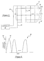
- conductors 40 may comprise conventional and commercially available wires, film, or traces which are currently used to selectively defrost a vehicular window. Such wires or traces may also be utilized on the windshield 22 and/or upon the windows 24 as previously explained and, as best shown in Figure 2, conductors 40 form a selectively energisable grid or array.
- conductors 40 are substantially and linearly co-extensive with the back window 20 and in one non-limiting embodiment of the invention, conductors 40 are substantially identical, although they are not necessarily required to be identical. Further, each of the conductors 40 is coupled, at a respective location or "ground point" 41, to electrical ground potential 42, and each of the conductors 40 have respective opposed ends 44, 46 which are physically and communicatively coupled to the controller 30.
- the ends 46 cooperatively form a bus 48 which is physically and communicatively coupled to the controller 30, and the ends 44 cooperatively form a bus 50 which is also physically and communicatively coupled to the controller 30.
- each respective "ground point” 41 is physically coupled to electrical ground potential 42 by bus 47.
- bus 50, conductors 40 and bus 47 cooperatively form a first relatively small conductive portion 60
- bus 48, conductors 40, and bus 47 cooperatively form a second relatively small conductive portion 62 that is to say, the portions 60 and 62 "divide" the back window 20 into two relatively small halves or portions.
- each of the portions 60, 62 are substantially identical, although in other embodiments of the invention, portions 60, 62 may be dissimilar in size and/or shape.
- the apparatus 12 further includes a selectively movable switch 51 which is physically and communicatively coupled to the controller 30 by bus 39 and which may be selectively moved from a first deactivated position 53 to a plurality of alternate positions.
- switch 51 may include a second position 55, a third position 57, and a fourth position 59.
- the controller 30 senses the position 53-59 of the switch 51 and performs certain operations which depend upon the sensed switch position 53-59 and the program/instructions included within the controller 30. The operation of the apparatus 12 will now be explained with respect to back window 20.
- controller 30 causes electrical power to be communicated from the battery 26, to the bus 50, thereby allowing the portion 60 to be heated.
- the communicated electrical current flows through the bus 50, through ends 44 of each of the conductors 40, and to the respective "ground points" 41 and the electrical ground potential 42.
- These portions of the conductors 40 which reside within and which form the conductive portion 60 therefore heat and defrost that portion of the back window 20 which includes or which is otherwise in operative contact with portion 60.
- the electrical energy which may have been communicated to bus 48 is also interrupted when the switch 51 is moved to position 55.
- controller 30 When the switch 51 is moved to position 57, controller 30 causes electrical power to be communicated from the battery 26 to the bus 48, thereby allowing conductive portion 62 to be energized and to provide heat. That is, the communicated electrical current flows through the bus 48, through ends 46 of the conductors 40, and to the respective "ground points" 41 and the ground potential 42. These portions of the conductors 40 which reside within and which form the conductive portion 62 heat and defrosts that portion of the back window 20 which includes or which otherwise in operative contact with portion 62.
- the foregoing strategy of heating relatively small areas of the back window 20 allows the entire back window 20 to be quickly heated since the entire amount of power communicated to the controller 30 and supplied by the battery 26 is applied to only one of the relatively small areas or portions at any time.
- the heating efficiency of this strategy was verified by an experiment conducted on a Year 2001 model of a FOCUS type vehicle which is manufactured by the Ford Motor Company of Dearborn, Michigan. Particularly, the vehicle was placed in a climate controlled chamber for about twelve hours. The climate controlled chamber provided a temperature of 0 degrees Fahrenheit and a wind speed of approximately 5 mph (i.e., the initial vehicular placement time is referred to as "the soaking time"). A thin layer of water was then deposited upon the back window of the vehicle and the vehicle was allowed to "soak" for an additional 30 minutes within the climate controlled chamber to allow the deposited water to form a layer of ice or frost upon the back window of the vehicle. Approximately 12.8 volts and 20 amps of electrical energy were supplied to a conventional conductor arrangement which traversed substantially the entire back window of the vehicle in the traditional manner. The back window was defrosted in about thirty-five minutes.
- the test was repeated with the voltage across the conductors (i.e., referred to as "grid voltage”) increased to about 18.1 volts to simulate the effect of doubling the power to the entire back window or equivalently using the same power (i.e., the power derived from 12.8 volts) over half of the back window. That is, it is known by Joule's Law that the electrical power is equal to the square of the provided voltage divided by resistance. Hence, according to this law, a voltage of 18.1 volts provides almost double the power which is provided by a voltage which is 12.8 volts over the same electrical resistance.
- the back window was defrosted in about seven minutes when the utilized grid voltage was tested at 18.1 volts.
- the defrosting time was reduced by a factor of five (from thirty-five minutes to seven minutes) which is a significantly larger amount than the number of portions that need to be defrosted (e.g., such window portions corresponding to heating portions 60, 62).
- the entire back window 20 may be defrosted in about two-fifths of the amount of time which would be required to defrost the entire back window 20 by applying the same power in a conventional manner to one conductor array or assembly which traverses the entire back window 20 (i.e., separately defrosting two halves of the back window 20 takes approximately 14 minutes instead of the 35 minutes required if both portions were concurrently defrosted in a conventional manner).
- the use of apparatus 12 allows a savings of about 60% of the energy required to accomplish the same defrosting task to be realized (i.e., by defrosting the entire back window 20 in about 40% of the time).
- the back window 20 may be segmented into three or more such portions or segments.
- the controller 30 physically and communicatively couples the bus 48 to the battery or energy source 26 (e.g., allowing energy to be sourced from battery 26 to the bus 48) for a certain first predetermined period of time and then interrupts or substantially prevents the battery or energy source 26 from communicating with the bus 48 while causing the bus 50 to be similarly, physically, and communicatively coupled to the battery or energy source 26 for a second predetermined period of time.
- the first and second predetermined periods of time are substantially identical, however, in other non-limiting embodiments, the first and second predetermined periods of time may be disparate.
- the controller 30 then physically and communicatively couples the bus 48 to the battery or energy source 26 for a period of time which is substantially equal to the first predetermined period of time, while interrupting or terminating the communication between the bus 50 and the battery or energy source 26.
- the controller 30 alternatively couples the busses 48 and 50 to the energy source 26 until the back window 20 has been substantially defrosted (e.g., each such "alternating coupling" continues for a third predetermined period of time) or until a sensor, such as temperature sensor 49, which is deposed upon back window 20 and which is coupled to the controller 30 by bus 70, determines that the back window 20 has attained a certain desired temperature and communicates this information to the controller 30.
- a sensor such as temperature sensor 49
- controller 30 may estimate the temperature of back window 20 by determining the actual electrical resistance of the coupled array or grid of conductors 40 ("the grid resistance") by measuring the electrical current which is being applied or which is being communicated to the apparatus 12 for a certain applied voltage. The grid resistance may then be compared to a database or matrix stored within controller 30 which contains known or previously determined grid resistance values over a range of temperatures for a certain applied voltage (e.g., the resistance value of the grid varies with temperature in a known or easily calibratable manner).
- the grid resistance the actual electrical resistance of the coupled array or grid of conductors 40
- another temperature sensor which may be substantially similar to temperature sensor 49, may be disposed upon the rear window 20, or substantially any other window 22, 24, or any other desired location within or outside of the vehicle 10 and is communicatively coupled to the controller 30.
- This temperature sensor then measures the ambient temperature of the environment that the vehicle 10 is disposed within and controller 30 uses this information to determine whether apparatus 12 should be activated. For example, if the measured ambient temperature is at least seventy-five degrees Fahrenheit, controller 30 substantially prevents electrical power to be sourced to either of the busses 48, 50 since there is very little likelihood of any frosting or any fogging being deposited or occurring upon the back window 20.
- the measured ambient temperature is between about forty and about seventy-five degrees Fahrenheit, there could be fogging but not frosting on windows 20, 22, 24, and hence a certain fixed amount of electrical power may be applied to the respective regions of apparatus 12 (e.g., a reduced amount of power is communicated to the grid 40 to or the individual portions 60, 62 to defog the windows 20, 22, 24).
- conductors 40 may form substantially any desired pattern upon or within the windows 20, 22, and 24, such as the "horizontal pattern" which is shown in Figure 2 (i.e., a pattern in which the conductors 40 are substantially parallel to the respective longitudinal axis of symmetry 100 of the window 20, 22, 24 upon which or in which they are deployed). As shown best in Figure 3, these conductors 40 may also be "vertically deployed” upon or within the window 20, 22 and 24 (i.e., being substantially perpendicular to the respective longitudinal axis of symmetry 100 of the window 20, 22, 24 upon or in which they are deployed). It should also be appreciated that conductors 40 may be coupled to electrical ground potential 42 at substantially any desired point or location along their respective length.
- conductors 40 form two selectively energisable assemblies and respectively have two separate energisation paths.
- bus 50 is physically and communicatively coupled to the battery 26 a first energy path is formed in each conductor 40 from each respective end 44 to the electrical ground potential 42, through bus 47.
- This respective first energy path which is associated with or provided by each conductor 40 cooperatively forms a first heating or energisation assembly 60 which selectively heats a first half or portion of back window 20.
- bus 48 is physically and communicatively coupled to the battery 26 a second energy path is formed in each conductor 40 from each respective end 46 to the electrical ground potential 42, through the bus 47.
- This respective second energy path associated with or provided by each conductor 40 cooperatively forms a second heating or energisation assembly 62 which selectively heats the second half or portion of the back window 20.
- This alternating activation of the busses 48 and 50 allows a greater amount of energy to be communicated to the windows 20, 22, 24 from the battery or energy source 26 since this methodology allows or provides alternating inputs or pulses of energy to these conductors 40. The benefit provided by such pulsed energy is explained in greater detail below.
- R(T) R(T0)*(1+Alpha * (Delta T))
- R(T) is the "grid resistance” (e.g., the resistance of the coupled array or grid of conductors 40) at a certain ambient temperature "T”
- R(T0) is the grid resistance at a known temperature of "T0”
- Alpha is the temperature coefficient of the material used to make the conductors 40 and is a known quantity
- Delta T (T-T0) and is equal to the difference between the temperature of "T” and the temperature of "T0"
- I V/R(T)
- V denotes the voltage communicated to the array or grid of conductors 40 and, more particularly, is typically equal to twelve volts (i.e., a possible voltage of battery 26); and "I” is the amount of electrical current traversing the grid of conductors 40.
- the amount of electrical current is inversely proportional to the resistance of the conductors 40.
- a model may be made of the change in current and resistance as the temperature of the conductors 40 increases.
- the controller 30 may automatically cause power being supplied to the first portion 60 to be interrupted and to cause the power to be communicated to the second portion 62 before the resistance of the conductors 40 within the first portion 60 appreciably increases. Such an energy interruption methodology may also be applied to portion 62.
- controller 30 may automatically cause power to be interrupted to the portions 60, 62 when the respective resultant current "I" drops below a certain threshold amount (e.g., below 18 amperes), thereby obviating the need for a temperature sensor 49.
- a certain threshold amount e.g., below 18 amperes
- a bi-metal strip or assembly which is disposed right at the back window 20 and which may be coupled to controller 30 may be utilized to accomplish both the switching between the different regions 60, 62 of the windows 20, 22, 24 as well as controlling/determining the need to engage the defroster (e.g., if the temperature is above 75 degrees Fahrenheit, a bi-metal assembly could be used to interrupt power to the defroster).
- the rapid pulsing required by the preferred embodiment of the invention, allows greater amounts of such electrical current and heating power to be generated by the conductors 40 during an interval of time, since the pulses have a width or a duration which corresponds to the time during which changes in resistance of the conductors 40 are minimized.
- a pulse width of between five and thirty seconds allows a current of between 18 to about 20 amperes to traverse the conductors 40 without appreciably raising the temperature of the conductors 40 above "T0".
- each assembly 60, 62 since the two heating assemblies or portions 60, 62 are not concurrently operated, a conventional twelve volt vehicular battery, or substantially any other desired vehicular battery may be utilized since each assembly 60, 62 only utilizes the voltage and current provided by a conventional vehicular battery 26 to effectively defrost back window 20. This is graphically shown by graph 80 of Figure 4.
- each of the provided pulses 82 which are communicated, to a conductors 40 delivers a substantially identical amplitude of current 84 (e.g., about 18 to about 20 amperes).
- a substantially identical amplitude of current 84 e.g., about 18 to about 20 amperes.
- sensors may be adapted to automatically identify defrosted areas, communicate this information to controller 30, and have controller 30 automatically cause these defrosted areas to no longer be heated (i.e., to no longer receive electrical power).
- Another approach entails defrosting the center of the window and progressing towards the edges or from top to bottom in order to allow the melted ice to aid in the defrosting process.
- one example of such a modification is to provide an "automatic" defrost capability whereby controller 30 activates apparatus 12 when the temperature of back window 20 drops below a certain threshold level.
- the controller 30 may monitor the back window 20 temperature through either temperature sensor 49 or by using the grid resistance of conductors 40 to estimate the temperature in the manner delineated above.
Landscapes
- Surface Heating Bodies (AREA)
Abstract
Description
"R(T0)" is the grid resistance at a known temperature of "T0" ;
"Alpha" is the temperature coefficient of the material used to make the
"Delta T" = (T-T0) and is equal to the difference between the temperature of "T" and the temperature of "T0"
"I" is the amount of electrical current traversing the grid of
Claims (10)
- An apparatus (12) for heating a part (20, 22, 24) of a vehicle (10) characterised in that the apparatus (12) comprises a first portion (60) which heats a first portion of the part of the vehicle and a second portion (62) which heats a second portion of the part (20, 22, 24) of the vehicle (10).
- An apparatus as claimed in claim 1 in which the part of the vehicle is a window (20, 22, 24) of the vehicle (10).
- An apparatus as claimed in Claim 2 wherein said second portion (62) heats said second portion of said window (20, 22, 24) only when said first portion (60) stops heating said first portion of said window (20, 22, 24).
- An apparatus as claimed in any of Claims 1 to 3 wherein the apparatus (12) further comprises a switch (51) which is coupled to a controller (30) and which selectively allows only said first part of said window (20, 22, 24) to be heated.
- An apparatus as claimed in claim 1 or in claim 2 comprising a plurality of conductors (40) which communicate with said part (20, 22, 24) of said vehicle (10) so as to selectively provide heat thereto, each of said plurality of conductors (40) being coupled to an electrical ground potential (42) and including the respective first portion (60) which selectively receives energy and which produces heat by use of said energy and the respective second portion (62) which selectively receives said energy and which produces heat by use of said energy only when said communication of said energy to said first portion (60) is interrupted.
- An apparatus as claimed in Claim 5 further comprising a controller (30) which is coupled to said plurality of conductors (40) and which senses the resistance of said second portion (62) and which interrupts said communication of said energy to said second portion (62) based upon said sensed resistance.
- An apparatus as claimed in Claim 6 further comprising a temperature sensor (49) which is coupled to said part (20, 22, 24) of said vehicle (10) and to said controller (30) .
- An apparatus as claimed in Claim 7 wherein said temperature sensor (49) senses the temperature of said part (20, 22, 24) of said vehicle (10) and, based upon said sensed temperature, interrupts said communication of said energy to said second portion (62).
- An apparatus as claimed in wherein said vehicle resides within a certain environment and said apparatus further comprises a second temperature sensor which senses the temperature of the environment within which the vehicle (10) resides and, based upon said sensed environment temperature, causes energy to be communicated to said second portion (62).
- A method for heating a vehicular window (20, 22, 24) characterised in that the method comprises the steps of heating a first portion of said window (20, 22, 24) and heating a second portion of said window (20, 22, 24) after said first portion of said window (20, 22, 24) has been heated.
Applications Claiming Priority (2)
| Application Number | Priority Date | Filing Date | Title |
|---|---|---|---|
| US09/682,947 US6521868B1 (en) | 2001-11-02 | 2001-11-02 | Method and apparatus for heating a portion of a vehicle |
| US682947 | 2001-11-02 |
Publications (2)
| Publication Number | Publication Date |
|---|---|
| EP1309227A2 true EP1309227A2 (en) | 2003-05-07 |
| EP1309227A3 EP1309227A3 (en) | 2006-09-06 |
Family
ID=24741902
Family Applications (1)
| Application Number | Title | Priority Date | Filing Date |
|---|---|---|---|
| EP02102498A Withdrawn EP1309227A3 (en) | 2001-11-02 | 2002-10-27 | A Method and Apparatus for Heating part of a Vehicle |
Country Status (2)
| Country | Link |
|---|---|
| US (1) | US6521868B1 (en) |
| EP (1) | EP1309227A3 (en) |
Families Citing this family (6)
| Publication number | Priority date | Publication date | Assignee | Title |
|---|---|---|---|---|
| JP3773433B2 (en) * | 2000-10-11 | 2006-05-10 | シャープ株式会社 | Ambient monitoring device for moving objects |
| US20050040151A1 (en) * | 2003-08-20 | 2005-02-24 | Robert Dyrdek | Heated side window glass |
| US20070101753A1 (en) * | 2005-10-06 | 2007-05-10 | Mile High Equipment Llc | Thermally conductive ice-forming surfaces incorporating short-duration electro-thermal deicing |
| EP2221199B1 (en) * | 2007-12-13 | 2012-02-29 | Panasonic Corporation | Vehicle heating system |
| US11582836B2 (en) * | 2019-09-23 | 2023-02-14 | Ford Global Technologies, Llc | Backlight window defrosting system based on field of view |
| US11405984B2 (en) * | 2020-01-22 | 2022-08-02 | Ford Global Technologies, Llc | Motor vehicle including heater for exterior interface |
Family Cites Families (23)
| Publication number | Priority date | Publication date | Assignee | Title |
|---|---|---|---|---|
| US1758703A (en) * | 1929-01-30 | 1930-05-13 | Jack A Johnson | Windshield |
| US2530980A (en) * | 1949-03-01 | 1950-11-21 | Westinghouse Electric Corp | Control system for window heaters |
| US2866881A (en) * | 1955-12-19 | 1958-12-30 | Kearfott Company Inc | Temperature controlled electrically heated window and window wiper system |
| US3475588A (en) * | 1968-08-20 | 1969-10-28 | Permaglass | Defrosting and deicing window assembly |
| US3832527A (en) | 1970-12-18 | 1974-08-27 | Asahi Glass Co Ltd | Defogging glass plate |
| US3790745A (en) * | 1972-10-13 | 1974-02-05 | Sierracin Corp | Temperature control for electrically heatable window |
| US3982092A (en) * | 1974-09-06 | 1976-09-21 | Libbey-Owens-Ford Company | Electrically heated zoned window systems |
| US4127763A (en) * | 1975-04-17 | 1978-11-28 | Saint-Gobain Industries | Heated window with a moisture sensor having a high impedance |
| US4357524A (en) | 1980-01-29 | 1982-11-02 | Westinghouse Electric Corp. | Electrical heater controller for aircraft window heat control |
| GB2091528B (en) | 1981-01-14 | 1984-11-07 | Boussois Sa | Heatable panels |
| DE3226393A1 (en) | 1982-07-15 | 1984-01-19 | Flachglas AG, 8510 Fürth | HEATABLE VEHICLE WINDOW |
| JPS59137237A (en) | 1983-01-28 | 1984-08-07 | Nissan Motor Co Ltd | Electric current supply device of heating element for car |
| USRE33343E (en) * | 1984-06-14 | 1990-09-18 | Donnelly Corporation | Crack detector for electrically conductive windshield |
| US4725710A (en) | 1985-11-07 | 1988-02-16 | Ford Motor Company | Electrically heatable vision unit |
| DE3844607C3 (en) | 1988-01-20 | 1997-03-13 | Ver Glaswerke Gmbh | Power supply circuit for a motor vehicle with two different consumer voltages |
| JPH01233140A (en) | 1988-03-14 | 1989-09-18 | Nissan Motor Co Ltd | Ice melting device for window glass for vehicle |
| DE3942593A1 (en) | 1989-12-22 | 1991-06-27 | Bosch Gmbh Robert | DEVICE FOR ENERGY SUPPLYING A HEATING DISC FROM THE VEHICLE SYSTEM |
| US5072098A (en) * | 1990-06-11 | 1991-12-10 | Chrysler Corporation | Electrically heated windshield controller |
| US5451822A (en) | 1991-03-15 | 1995-09-19 | Gentex Corporation | Electronic control system |
| US5182431A (en) | 1991-12-18 | 1993-01-26 | Ppg Industries, Inc. | Electrically heated window |
| US6163013A (en) * | 1992-12-07 | 2000-12-19 | Navistar International Transportation Corp | Continuous duty direct current heated windshield with ambient temperature limit switch |
| US5831244A (en) | 1997-10-30 | 1998-11-03 | Springer, Jr.; Edward Leo | Vehicular electric heater |
| US6100500A (en) * | 1998-05-19 | 2000-08-08 | Jefferson, Jr.; Bobby J. | Vehicle glass clearing system |
-
2001
- 2001-11-02 US US09/682,947 patent/US6521868B1/en not_active Expired - Fee Related
-
2002
- 2002-10-27 EP EP02102498A patent/EP1309227A3/en not_active Withdrawn
Also Published As
| Publication number | Publication date |
|---|---|
| EP1309227A3 (en) | 2006-09-06 |
| US6521868B1 (en) | 2003-02-18 |
Similar Documents
| Publication | Publication Date | Title |
|---|---|---|
| US3475588A (en) | Defrosting and deicing window assembly | |
| US4109133A (en) | Electrically heated rear window for automotive vehicles | |
| US5798499A (en) | Electrically heating windshield glass having a substantially uniform thermal distribution | |
| US3982092A (en) | Electrically heated zoned window systems | |
| EP0849977B1 (en) | Arrangement for heating the wiper rest area of a vehicle windshield | |
| US20090206068A1 (en) | Window-glass heating device | |
| US6521868B1 (en) | Method and apparatus for heating a portion of a vehicle | |
| KR102649643B1 (en) | car glazing fog eliminator | |
| DE10120098B4 (en) | Heating and method for controlling the heating of a functional unit of a motor vehicle | |
| US20120193338A1 (en) | Apparatus for removing ice and snow from the roof of a vehicle | |
| CA2969048A1 (en) | Transparent pane with an electrical heating layer and production method therefor | |
| JP3918728B2 (en) | Electric heating glass device | |
| CN105764171A (en) | Selective heating of vehicle side window | |
| DE19821123B4 (en) | Switching device for a defrosting device of a vehicle window | |
| EP4691173A1 (en) | Electronic controller for rapid defrosting and automated defogging in vehicles | |
| WO2017110206A1 (en) | Heater control apparatus | |
| CA2093479A1 (en) | Continuous duty direct current heated windshield with ambient temperature limit switch | |
| JP2004210153A (en) | Defogger control device for vehicles | |
| JP5204057B2 (en) | Heater control device | |
| US6137085A (en) | Arrangement of heating strips of defogger on vehicle window glass | |
| US6037573A (en) | System and method for controlling the operation of a heated wiper area | |
| CN118514788B (en) | Design method and control method of automobile glass and vehicle | |
| JP2002264780A (en) | Cloud prevention glass for vehicle | |
| JP3022242B2 (en) | Rearview mirror for vehicle | |
| EP0506797B1 (en) | Independent heating system for a motor vehicle |
Legal Events
| Date | Code | Title | Description |
|---|---|---|---|
| PUAI | Public reference made under article 153(3) epc to a published international application that has entered the european phase |
Free format text: ORIGINAL CODE: 0009012 |
|
| AK | Designated contracting states |
Designated state(s): AT BE BG CH CY CZ DE DK EE ES FI FR GB GR IE IT LI LU MC NL PT SE SK TR |
|
| AX | Request for extension of the european patent |
Extension state: AL LT LV MK RO SI |
|
| PUAL | Search report despatched |
Free format text: ORIGINAL CODE: 0009013 |
|
| AK | Designated contracting states |
Kind code of ref document: A3 Designated state(s): AT BE BG CH CY CZ DE DK EE ES FI FR GB GR IE IT LI LU MC NL PT SE SK TR |
|
| AX | Request for extension of the european patent |
Extension state: AL LT LV MK RO SI |
|
| 17P | Request for examination filed |
Effective date: 20070202 |
|
| 17Q | First examination report despatched |
Effective date: 20070308 |
|
| AKX | Designation fees paid |
Designated state(s): DE GB SE |
|
| STAA | Information on the status of an ep patent application or granted ep patent |
Free format text: STATUS: THE APPLICATION IS DEEMED TO BE WITHDRAWN |
|
| 18D | Application deemed to be withdrawn |
Effective date: 20070719 |