EP1308761A1 - Optical fibre alignment device and method - Google Patents
Optical fibre alignment device and method Download PDFInfo
- Publication number
- EP1308761A1 EP1308761A1 EP01309227A EP01309227A EP1308761A1 EP 1308761 A1 EP1308761 A1 EP 1308761A1 EP 01309227 A EP01309227 A EP 01309227A EP 01309227 A EP01309227 A EP 01309227A EP 1308761 A1 EP1308761 A1 EP 1308761A1
- Authority
- EP
- European Patent Office
- Prior art keywords
- optical fibre
- fibre
- laser diode
- universal joint
- mount
- Prior art date
- Legal status (The legal status is an assumption and is not a legal conclusion. Google has not performed a legal analysis and makes no representation as to the accuracy of the status listed.)
- Granted
Links
Images



Classifications
-
- G—PHYSICS
- G02—OPTICS
- G02B—OPTICAL ELEMENTS, SYSTEMS OR APPARATUS
- G02B6/00—Light guides; Structural details of arrangements comprising light guides and other optical elements, e.g. couplings
- G02B6/24—Coupling light guides
- G02B6/42—Coupling light guides with opto-electronic elements
- G02B6/4201—Packages, e.g. shape, construction, internal or external details
- G02B6/4219—Mechanical fixtures for holding or positioning the elements relative to each other in the couplings; Alignment methods for the elements, e.g. measuring or observing methods especially used therefor
- G02B6/4236—Fixing or mounting methods of the aligned elements
- G02B6/4237—Welding
-
- G—PHYSICS
- G02—OPTICS
- G02B—OPTICAL ELEMENTS, SYSTEMS OR APPARATUS
- G02B6/00—Light guides; Structural details of arrangements comprising light guides and other optical elements, e.g. couplings
- G02B6/24—Coupling light guides
- G02B6/42—Coupling light guides with opto-electronic elements
- G02B6/4201—Packages, e.g. shape, construction, internal or external details
- G02B6/4219—Mechanical fixtures for holding or positioning the elements relative to each other in the couplings; Alignment methods for the elements, e.g. measuring or observing methods especially used therefor
- G02B6/422—Active alignment, i.e. moving the elements in response to the detected degree of coupling or position of the elements
- G02B6/4226—Positioning means for moving the elements into alignment, e.g. alignment screws, deformation of the mount
-
- G—PHYSICS
- G02—OPTICS
- G02B—OPTICAL ELEMENTS, SYSTEMS OR APPARATUS
- G02B6/00—Light guides; Structural details of arrangements comprising light guides and other optical elements, e.g. couplings
- G02B6/24—Coupling light guides
- G02B6/42—Coupling light guides with opto-electronic elements
- G02B6/4201—Packages, e.g. shape, construction, internal or external details
- G02B6/4219—Mechanical fixtures for holding or positioning the elements relative to each other in the couplings; Alignment methods for the elements, e.g. measuring or observing methods especially used therefor
- G02B6/422—Active alignment, i.e. moving the elements in response to the detected degree of coupling or position of the elements
- G02B6/4221—Active alignment, i.e. moving the elements in response to the detected degree of coupling or position of the elements involving a visual detection of the position of the elements, e.g. by using a microscope or a camera
- G02B6/4224—Active alignment, i.e. moving the elements in response to the detected degree of coupling or position of the elements involving a visual detection of the position of the elements, e.g. by using a microscope or a camera using visual alignment markings, e.g. index methods
Definitions
- This invention relates to a device and method for aligning an optical fibre with the output facet of a laser diode.
- Coupling efficiency between an optical fibre and a laser diode is limited by the accuracy and stability of the alignment achievable during the assembly process.
- Alignment of an optical fibre and a laser diode may be achieved by placing the optical fibre using a feature which has been etched onto a silicon 'optical bench', upon which the laser diode has already been precisely attached.
- this simple technique is limited in precision by the manufactured accuracy of the silicon and the fibre and subsequent movement due to thermal stresses during the joining process.
- Another technique uses a mount to support the optical fibre. Once the laser and the optical fibre have been aligned and attached to the bench, the mount is mechanically deformed until an optimum coupling efficiency is achieved.
- this technique suffers from the disadvantage of creep or flow of the deformed material and is therefore not stable in the long term.
- Creep is a natural result of the aging process, but is more acute where materials are subjected to stress. Furthermore, the problem of creep is increased due to the high temperature to which such coupling assemblies are likely to be subjected. Such creep reduces the coupling efficiency between the laser and the fibre as the assembly ages.
- a high coupling efficiency between a fibre and a laser diode is aimed for, therefore it is important that the fibre tip is at an optimum distance from the laser diode, typically between 5 ⁇ m and 10 ⁇ m from the laser facet.
- the fibre tip is so close to the output facet of the laser this means that a small displacement from the optimum position causes a significant drop in coupling efficiency.
- displacements from the optimum position do not have such a great effect but coupling efficiency is reduced. Therefore it is important in a coupling device which is aiming for a high efficiency of coupling that the device is stable, i.e. that ageing does not cause the tip of the fibre to be displaced even a small amount from an optimum coupling position.
- This invention serves to alleviate such problems of reliability and stability, and is particularly beneficial for components requiring high reliability.
- a device for aligning an optical fibre with the output facet of a laser diode to obtain a substantially optimum coupling efficiency comprising
- the universal joint comprises a flexible material between the optical fibre and a mount.
- the adjustment means comprises a disk supporting the optical fibre having a spring for biasing the ball into the socket, and in which displacement of the disk results in a pivotal movement of the fibre about the centre of the ball, and a corresponding smaller displacement of the end of the optical fibre.
- a method of aligning an optical fibre with the output facet of a laser diode in which the laser diode is supported on a mount, the method comprising the steps of passively aligning the output facet of the laser diode with the end of fibre; attaching the laser diode to the mount; actively aligning the end of the fibre with the laser diode, using a fine adjustment means supporting the fibre at a point displaced from a universal joint through which the fibre passes, by displacing the fine adjustment means to cause the optical fibre to pivot about a pivotal point of the universal joint and to induce a corresponding smaller displacement in the end of the optical fibre, until a substantially optimum coupling efficiency is achieved; and securing the optical fibre in the position which achieves said substantially optimum coupling efficiency.
- the securing step comprises attaching the fine adjustment means to the mount.
- a laser diode 5 is mounted on a thermally conductive bench 3.
- the bench is fabricated from a material with a low thermal expansion coefficient such as Kovar, a nickel cobalt iron alloy.
- a material with a low thermal expansion coefficient such as Kovar, a nickel cobalt iron alloy.
- Other materials that work well include copper tungsten alloys which are materials which combine the conductivity of copper, thus providing heat spreading, with the low expansion coefficient of tungsten.
- Other suitable materials may be used for fabrication of the bench 3. It is possible to calculate limits for the thermal expansion of the chosen material, and to compensate for such expansion when designing the assembly.
- the bench 3 and an optical fibre 6, which is mounted in a stainless steel tube 8, are co-located in a mount 4.
- the optical fibre is inserted centrally in the stainless steel tube. Any misalignment of the optical fibre 6 with the centre of the tube 8 is compensated for during a passive alignment procedure, which is described later.
- the laser diode 5 is coupled directly to the fibre 6, without the necessity for a focussing lens between the end of the laser diode and the fibre core, although it will be understood by those skilled in the art that this invention is also applicable to alignment of a fibre with a laser diode where a focussing lens is used.
- the mount 4 has a hollow and generally cylindrical portion which houses a ball 1.
- the ball 1 may be glass or ceramic or stainless steel, for example.
- the ball 1 has an aperture passing through the centre, which receives the fibre 6 together with the tube 8.
- the ball 1 is biased against an internal conical socket in the mount, which has a co-axial aperture through which the optical fibre protrudes.
- the ball and the conical socket act together to form a universal joint with a pivotal point substantially at the centre of the ball 1.
- FIG 2 shows a sectional view from the side of the alignment device of figure 1, at the opposite end to the conical socket the generally cylindrical portion of the mount 4 has a larger aperture into which the fibre 6 together with the tube passes.
- the ball may be fabricated from a magnetic material which has been magnetised, the magnetic forces serving to bias the ball into the stainless steel conical socket.
- Rare earth magnets such as neodymium are especially suitable for this purpose as they have a high coercivity, which means that the magnetic forces will be greater for a lower volume of material.
- the laser diode 5 is aligned with the end of an optical fibre 6.
- Such alignment is referred to as passive alignment, because the devices are aligned optically (i.e. by eye with the aid of an optical microscope with approximately 50 to 250 times magnification).
- passive alignment lacks precision, firstly because although the laser diode generally has an active stripe which may be used to aid alignment, the position of the stripe may lack precision.
- the passive alignment procedure is a planar alignment, therefore, because the output facet of the laser may not be precisely manufactured such that the output facet may not be set at precisely 90° to the top and sides of the laser diode, the fibre 6 is unlikely to be in the optimum orientation after such passive alignment.
- the bench 3 After the fist stage of alignment the bench 3 is welded to the mount 4. During the welding process some relative movement between the laser diode 5 and the optical fibre 6 is likely to occur due to thermal stresses caused by the localised heating of material at the base of the bench 3.
- the light from the laser diode 5 is emitted in a conical shape. It is important to place the tip of the fibre at the point of maximum power.
- Figure 3 illustrates an example of how coupling efficiency is affected by the angular orientation of the fibre in perpendicular planes, and also how the coupling efficiency is affected by coaxial rotation of the fibre.
- Rotation of the fibre in the vertical plane is illustrated by the line is illustrated by the line 32
- rotation in the horizontal plane is illustrated by the line 33
- coaxial rotation is illustrated by the line 31.
- Displacement of the disk 7 is used to finely align the end of the optical fibre 6 with the laser diode 5.
- This fine alignment is an active alignment, meaning that the alignment is carried out with the laser switched on, and the coupling between the laser diode 5 and the optical fibre 6, is measured. Once a maximum coupling efficiency is achieved then the laser diode and the optical fibre are considered to be optimally aligned.
- Displacement of the disk 7 causes rotation of the optical fibre 6 about the pivotal point of the universal joint formed by the ball and the conical socket.
- the ratio of the distance between the pivotal point and the disk, and the distance between the pivotal point and the end of the fibre is approximately 9:1 in this embodiment of the invention. Therefore, displacement of the disk by a particular amount, results in a corresponding displacement of the end of the fibre by one ninth that amount.
- the maximum rotation angle is set to 2°.
- Figure 4 illustrates an example lever design, where an optical fibre 42 pivots about a point 40.
- the fibre is rotated by displacement of the disk 7 and the power of the optical signal in the fibre is measured. Once the position at which a maximum power is obtained, that position is recorded as the optimum coupling position. Once the optimum coupling efficiency has been achieved during the active alignment procedure by displacement of the disk 7, the disk 7 is spot welded at three circumferentially equidistant points around the larger aperture of the mount 4. Three equidistant welded points have been found to be very stable, although it is possible to use more welds. In the welding machines used in the embodiment of the invention described, it is convenient to rotate the welder by 60° and spot weld at three more equidistant points to create six equidistant spot welds.
- any displacement of the disk will only cause a displacement of the fibre tip of one ninth of that displacement.
- the disk 7' is shown in more detail.
- the design of the disk 7' limits the amount of 'play' between the disk and the stainless steel tube 8' which occurs when the disk is displaced. If a circular aperture were used, for example, then the amount of play between the disk 7' and the tube 8' could be significant unless the aperture were precisely the same diameter as the tube 8'.
- the disk 7' is manufactured in such a way that the disk has built in concentric stresses, so that the disk has a high reluctance for coaxial misalignment.
- One technique is to use metal injection moulding to fabricate the disk. As the part shrinks built in stresses occur.
- the universal joint is not be formed using a ball and socket, as described previously, but it is formed using a flexible material between the tube and the mount as illustrated in Figures 6 and 7.
Landscapes
- Physics & Mathematics (AREA)
- General Physics & Mathematics (AREA)
- Optics & Photonics (AREA)
- Optical Couplings Of Light Guides (AREA)
Abstract
Description
- This invention relates to a device and method for aligning an optical fibre with the output facet of a laser diode.
- Coupling efficiency between an optical fibre and a laser diode is limited by the accuracy and stability of the alignment achievable during the assembly process. Alignment of an optical fibre and a laser diode may be achieved by placing the optical fibre using a feature which has been etched onto a silicon 'optical bench', upon which the laser diode has already been precisely attached. However, this simple technique is limited in precision by the manufactured accuracy of the silicon and the fibre and subsequent movement due to thermal stresses during the joining process. Another technique uses a mount to support the optical fibre. Once the laser and the optical fibre have been aligned and attached to the bench, the mount is mechanically deformed until an optimum coupling efficiency is achieved. However, this technique suffers from the disadvantage of creep or flow of the deformed material and is therefore not stable in the long term. Creep is a natural result of the aging process, but is more acute where materials are subjected to stress. Furthermore, the problem of creep is increased due to the high temperature to which such coupling assemblies are likely to be subjected. Such creep reduces the coupling efficiency between the laser and the fibre as the assembly ages.
- In the coupling device of this invention a high coupling efficiency between a fibre and a laser diode is aimed for, therefore it is important that the fibre tip is at an optimum distance from the laser diode, typically between 5µm and 10µm from the laser facet. However, as the fibre tip is so close to the output facet of the laser this means that a small displacement from the optimum position causes a significant drop in coupling efficiency. At distances further from the output facet of the laser, displacements from the optimum position do not have such a great effect but coupling efficiency is reduced. Therefore it is important in a coupling device which is aiming for a high efficiency of coupling that the device is stable, i.e. that ageing does not cause the tip of the fibre to be displaced even a small amount from an optimum coupling position.
- This invention serves to alleviate such problems of reliability and stability, and is particularly beneficial for components requiring high reliability.
- According to the present invention there is provided a device for aligning an optical fibre with the output facet of a laser diode to obtain a substantially optimum coupling efficiency, the device comprising
- a universal joint through which the optical fibre passes such that the end of the optical fibre is adjacent to the output facet of the laser diode; and
- an adjustment means located at a distance from the universal joint such that displacement of the adjustment means causes a pivotal movement of the fibre about a pivotal point of the universal joint and results in a smaller displacement of the end of the optical fibre.
-
- To aid hermetic sealing for high reliability, in one embodiment the universal joint comprises a flexible material between the optical fibre and a mount.
- In another embodiment the universal joint comprises
- a ball, having an aperture through the centre for receiving the optical fibre;
- a mount housing the ball;
- biasing means for biasing the ball into an internal conical socket within the mount, the socket having an aperture through which the optical fibre protrudes. In this embodiment the biasing force may be provided by the ball being magnetised, and the conical socket comprising a magnetic material or by some form of spring loading.
-
- Preferably the adjustment means comprises a disk supporting the optical fibre having a spring for biasing the ball into the socket, and in which displacement of the disk results in a pivotal movement of the fibre about the centre of the ball, and a corresponding smaller displacement of the end of the optical fibre.
- According to another aspect of the invention there is provided a method of aligning an optical fibre with the output facet of a laser diode, in which the laser diode is supported on a mount, the method comprising the steps of
passively aligning the output facet of the laser diode with the end of fibre;
attaching the laser diode to the mount;
actively aligning the end of the fibre with the laser diode, using a fine adjustment means supporting the fibre at a point displaced from a universal joint through which the fibre passes, by displacing the fine adjustment means to cause the optical fibre to pivot about a pivotal point of the universal joint and to induce a corresponding smaller displacement in the end of the optical fibre, until a substantially optimum coupling efficiency is achieved; and
securing the optical fibre in the position which achieves said substantially optimum coupling efficiency. - Preferably the securing step comprises attaching the fine adjustment means to the mount.
- Embodiments of the invention will now be described, by way of example only, with reference to the accompanying drawings, in which:
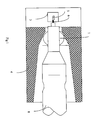
- Figure 1 is a cross section of part of an alignment device viewed from the top;
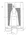
- Figure 2 is a cross section of the alignment device of figure 1 viewed from the side; and
- Figure 3 is a graph illustrating how coupling efficiency between a laser diode and an optical fibre is affected by the angular orientation of the fibre;
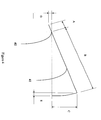
- Figure 4 illustrates parameters of a lever design;
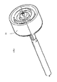
- Figure 5 is a perspective view, partially cut away, of an alignment device;
- Figure 6 shows part of a flexible joint which may be used as an alternative to a ball and socket joint; and
- Figure 7 is a perspective view, partially cut away, of an alignment device using the flexible joint of figure 6.
-
- Referring now to figure 1 a
laser diode 5 is mounted on a thermallyconductive bench 3. The bench is fabricated from a material with a low thermal expansion coefficient such as Kovar, a nickel cobalt iron alloy. Other materials that work well include copper tungsten alloys which are materials which combine the conductivity of copper, thus providing heat spreading, with the low expansion coefficient of tungsten. Other suitable materials may be used for fabrication of thebench 3. It is possible to calculate limits for the thermal expansion of the chosen material, and to compensate for such expansion when designing the assembly. - The
bench 3 and anoptical fibre 6, which is mounted in astainless steel tube 8, are co-located in amount 4. The optical fibre is inserted centrally in the stainless steel tube. Any misalignment of theoptical fibre 6 with the centre of thetube 8 is compensated for during a passive alignment procedure, which is described later. - The
laser diode 5 is coupled directly to thefibre 6, without the necessity for a focussing lens between the end of the laser diode and the fibre core, although it will be understood by those skilled in the art that this invention is also applicable to alignment of a fibre with a laser diode where a focussing lens is used. - The
mount 4 has a hollow and generally cylindrical portion which houses aball 1. Theball 1 may be glass or ceramic or stainless steel, for example. Theball 1 has an aperture passing through the centre, which receives thefibre 6 together with thetube 8. Theball 1 is biased against an internal conical socket in the mount, which has a co-axial aperture through which the optical fibre protrudes. The ball and the conical socket act together to form a universal joint with a pivotal point substantially at the centre of theball 1. - Referring now to figure 2, which shows a sectional view from the side of the alignment device of figure 1, at the opposite end to the conical socket the generally cylindrical portion of the
mount 4 has a larger aperture into which thefibre 6 together with the tube passes. Adisk 7, fabricated from copper tungsten, Kovar or stainless steel, for example, has aspring 9 for biasing theball 1 into the socket. Thedisk 7 is secured to thestainless steel tube 8. - In an alternative embodiment the ball may be fabricated from a magnetic material which has been magnetised, the magnetic forces serving to bias the ball into the stainless steel conical socket. Rare earth magnets such as neodymium are especially suitable for this purpose as they have a high coercivity, which means that the magnetic forces will be greater for a lower volume of material.
- Whatever material is used for manufacture of the ball, it is important that it is easy to form the cylindrical aperture in the ball, and that it is possible to manufacture a sphere to extremely high tolerances, so that irregularities in the shape of the ball don't cause any displacement from the optimum coupling position. Furthermore, it is important that the material is very hard so that it will not wear as the assembly ages.
- During a first stage of alignment, the
laser diode 5 is aligned with the end of anoptical fibre 6. Such alignment is referred to as passive alignment, because the devices are aligned optically (i.e. by eye with the aid of an optical microscope with approximately 50 to 250 times magnification). Such passive alignment lacks precision, firstly because although the laser diode generally has an active stripe which may be used to aid alignment, the position of the stripe may lack precision. Secondly, the passive alignment procedure is a planar alignment, therefore, because the output facet of the laser may not be precisely manufactured such that the output facet may not be set at precisely 90° to the top and sides of the laser diode, thefibre 6 is unlikely to be in the optimum orientation after such passive alignment. - After the fist stage of alignment the
bench 3 is welded to themount 4. During the welding process some relative movement between thelaser diode 5 and theoptical fibre 6 is likely to occur due to thermal stresses caused by the localised heating of material at the base of thebench 3. - The light from the
laser diode 5 is emitted in a conical shape. It is important to place the tip of the fibre at the point of maximum power. - Figure 3 illustrates an example of how coupling efficiency is affected by the angular orientation of the fibre in perpendicular planes, and also how the coupling efficiency is affected by coaxial rotation of the fibre. Rotation of the fibre in the vertical plane is illustrated by the line is illustrated by the
line 32, rotation in the horizontal plane is illustrated by theline 33, and coaxial rotation is illustrated by theline 31. In this example there is a difference in effect between rotation in a vertical plane and rotation in a horizontal plane. - Displacement of the
disk 7 is used to finely align the end of theoptical fibre 6 with thelaser diode 5. This fine alignment is an active alignment, meaning that the alignment is carried out with the laser switched on, and the coupling between thelaser diode 5 and theoptical fibre 6, is measured. Once a maximum coupling efficiency is achieved then the laser diode and the optical fibre are considered to be optimally aligned. - Displacement of the
disk 7 causes rotation of theoptical fibre 6 about the pivotal point of the universal joint formed by the ball and the conical socket. The ratio of the distance between the pivotal point and the disk, and the distance between the pivotal point and the end of the fibre is approximately 9:1 in this embodiment of the invention. Therefore, displacement of the disk by a particular amount, results in a corresponding displacement of the end of the fibre by one ninth that amount. In this embodiment of the invention it is possible to displace the disk accurately to within approximately 1µm (one micron), resulting in a corresponding displacement of the end of the fibre by approximately 111nm The maximum rotation angle is set to 2°. Figure 4 illustrates an example lever design, where an optical fibre 42 pivots about apoint 40. If A is set to be equal to 2mm then B is equal to 18mm for a 9:1 ratio, therefore for a required maximum rotation angle of 2° the maximum displacement C of the disk and the maximum displacement D of the fibre tip may be calculated as - The displacement E, inevitably caused by the rotation of the lever is calculated as follows.
- The fibre is rotated by displacement of the
disk 7 and the power of the optical signal in the fibre is measured. Once the position at which a maximum power is obtained, that position is recorded as the optimum coupling position. Once the optimum coupling efficiency has been achieved during the active alignment procedure by displacement of thedisk 7, thedisk 7 is spot welded at three circumferentially equidistant points around the larger aperture of themount 4. Three equidistant welded points have been found to be very stable, although it is possible to use more welds. In the welding machines used in the embodiment of the invention described, it is convenient to rotate the welder by 60° and spot weld at three more equidistant points to create six equidistant spot welds. - Whilst the spot welding of the disk may cause some relative movement between the end of the
fibre 6 and the output facet of thelaser diode 5, any displacement of the disk will only cause a displacement of the fibre tip of one ninth of that displacement. - Referring now to Figure 5 which shows a perspective view of an alternative embodiment of the invention, the disk 7' is shown in more detail. The design of the disk 7' limits the amount of 'play' between the disk and the stainless steel tube 8' which occurs when the disk is displaced. If a circular aperture were used, for example, then the amount of play between the disk 7' and the tube 8' could be significant unless the aperture were precisely the same diameter as the tube 8'. Ideally the disk 7' is manufactured in such a way that the disk has built in concentric stresses, so that the disk has a high reluctance for coaxial misalignment. One technique is to use metal injection moulding to fabricate the disk. As the part shrinks built in stresses occur.
- For high reliability, it is important that the assembly is sealed adequately. Any gaps between the ball and socket can be sealed using adhesive after the active alignment process described earlier.
- In an alternative embodiment which alleviates the sealing problem, illustrated in figure 6 and 7 the universal joint is not be formed using a ball and socket, as described previously, but it is formed using a flexible material between the tube and the mount as illustrated in Figures 6 and 7.
Claims (8)
- A device for aligning an optical fibre (6) with the output facet of a laser diode (5) to obtain a substantially optimum coupling efficiency, the device comprisinga universal joint through which the optical fibre passes such that the end of the optical fibre is adjacent to the output facet of the laser diode; andan adjustment means (7) located at a distance from the universal joint such that displacement of the adjustment means causes a pivotal movement of the fibre about a pivotal point of the universal joint and results in a smaller displacement of the end of the optical fibre.
- A device according to claim 1 in which the universal joint comprises a flexible material (60) between the optical fibre (6) and a mount (4).
- A device according to claim 1, in which the universal joint comprisesa ball (1), having an aperture through the centre for receiving the optical fibre;a mount (4) housing the ball;biasing means for biasing the ball into an internal conical socket within the mount, the socket having an aperture through which the optical fibre protrudes.
- A device according to claim 3 in which the ball is magnetised, and the conical socket comprises a magnetic material.
- A device according to any one of the preceding claims, in which the adjustment means comprises a disk (7) supporting the optical fibre having a spring (9) for biasing the ball into the socket, and in which displacement of the disk results in a pivotal movement of the fibre about the centre of the ball, and a corresponding smaller displacement of the end of the optical fibre.
- A device according to any one of the preceding claims further comprising a focussing lens located between the end of the optical fibre and the output facet of the laser diode.
- A method of aligning an optical fibre with the output facet of a laser diode, in which the laser diode is supported on a mount, the method comprising the steps of passively aligning the output facet of the laser diode with the end of fibre;
attaching the laser diode to the mount;
actively aligning the end of the fibre with the laser diode, using a fine adjustment means supporting the fibre at a point displaced from a universal joint through which the fibre passes, by displacing the fine adjustment means to cause the optical fibre to pivot about a pivotal point of the universal joint and to induce a corresponding smaller displacement in the end of the optical fibre, until a substantially optimum coupling efficiency is achieved; and
securing the optical fibre in the position which achieves said substantially optimum coupling efficiency. - A method according to claim 4 in which the securing step comprises attaching the fine adjustment means to the mount
Priority Applications (3)
| Application Number | Priority Date | Filing Date | Title |
|---|---|---|---|
| EP01309227A EP1308761B1 (en) | 2001-10-31 | 2001-10-31 | Optical fibre alignment device |
| DE60109456T DE60109456T2 (en) | 2001-10-31 | 2001-10-31 | Alignment device for optical fibers |
| US10/241,020 US6910811B2 (en) | 2001-10-31 | 2002-09-11 | Optical fiber alignment device and method |
Applications Claiming Priority (1)
| Application Number | Priority Date | Filing Date | Title |
|---|---|---|---|
| EP01309227A EP1308761B1 (en) | 2001-10-31 | 2001-10-31 | Optical fibre alignment device |
Publications (2)
| Publication Number | Publication Date |
|---|---|
| EP1308761A1 true EP1308761A1 (en) | 2003-05-07 |
| EP1308761B1 EP1308761B1 (en) | 2005-03-16 |
Family
ID=8182409
Family Applications (1)
| Application Number | Title | Priority Date | Filing Date |
|---|---|---|---|
| EP01309227A Expired - Lifetime EP1308761B1 (en) | 2001-10-31 | 2001-10-31 | Optical fibre alignment device |
Country Status (3)
| Country | Link |
|---|---|
| US (1) | US6910811B2 (en) |
| EP (1) | EP1308761B1 (en) |
| DE (1) | DE60109456T2 (en) |
Families Citing this family (6)
| Publication number | Priority date | Publication date | Assignee | Title |
|---|---|---|---|---|
| US20030095755A1 (en) * | 2001-11-16 | 2003-05-22 | Vladimir Vaganov | Feature and method to align and assemble photonic components |
| US20080013908A1 (en) * | 2006-01-03 | 2008-01-17 | 3M Innovative Properties Company | Total internal reflection prism mount |
| FR2962231B1 (en) * | 2010-07-02 | 2014-10-31 | Alcatel Lucent | METHOD FOR ALIGNING AND FIXING AN OPTICAL FIBER COUPLED WITH AN OPTOELECTRONIC COMPONENT |
| US8632262B2 (en) * | 2011-08-30 | 2014-01-21 | Kestrel Labs, Inc. | Laser to fiber optical coupling in photoplethysmography |
| JP2015016073A (en) * | 2013-07-10 | 2015-01-29 | ウシオ電機株式会社 | Optical fiber unit |
| HUP1800439A2 (en) | 2018-12-20 | 2020-06-29 | Equip Test Kft | Connector for connecting optical fibres and crimping device and release device therefor |
Citations (6)
| Publication number | Priority date | Publication date | Assignee | Title |
|---|---|---|---|---|
| JPS55166972A (en) * | 1979-06-13 | 1980-12-26 | Mitsubishi Electric Corp | Light semiconductor device |
| US4865410A (en) * | 1988-01-25 | 1989-09-12 | E. I. Du Pont De Nemours And Company | Decoupled fiber optic feedthrough assembly |
| JPH02245711A (en) * | 1989-03-20 | 1990-10-01 | Fujitsu Ltd | Optical fiber fixing device |
| EP0443454A2 (en) * | 1990-02-20 | 1991-08-28 | PIRELLI CAVI S.p.A. | Swivelling optical connector for joining optical fibres to discrete optical components and sensor using one or more optical connectors |
| US5937123A (en) * | 1998-04-22 | 1999-08-10 | Eastman Kodak Company | Fiber optical laser collimating device |
| US6074103A (en) * | 1996-10-15 | 2000-06-13 | Sdl, Inc. | Aligning an optical fiber with electroluminescent semiconductor diodes and other optical components |
Family Cites Families (6)
| Publication number | Priority date | Publication date | Assignee | Title |
|---|---|---|---|---|
| JPS6043889A (en) * | 1983-08-22 | 1985-03-08 | Hitachi Ltd | Light-emitting device |
| JPH1096839A (en) * | 1996-09-20 | 1998-04-14 | Sumitomo Electric Ind Ltd | Method for manufacturing semiconductor laser module |
| US6164837A (en) * | 1998-12-30 | 2000-12-26 | Mcdonnell Douglas Corporation | Integrated microelectromechanical alignment and locking apparatus and method for fiber optic module manufacturing |
| KR100322134B1 (en) * | 1999-02-06 | 2002-03-18 | 윤종용 | Apparatus for aligning optical source with optical fiber and optical source module comprising it |
| US6652158B2 (en) * | 2000-09-05 | 2003-11-25 | Optical Zonu Corporation | Optical networking unit employing optimized optical packaging |
| US6709169B2 (en) * | 2000-09-28 | 2004-03-23 | Powernetix, Inc. | Thermally and mechanically stable low-cost high thermal conductivity structure for single-mode fiber coupling to laser diode |
-
2001
- 2001-10-31 EP EP01309227A patent/EP1308761B1/en not_active Expired - Lifetime
- 2001-10-31 DE DE60109456T patent/DE60109456T2/en not_active Expired - Lifetime
-
2002
- 2002-09-11 US US10/241,020 patent/US6910811B2/en not_active Expired - Lifetime
Patent Citations (6)
| Publication number | Priority date | Publication date | Assignee | Title |
|---|---|---|---|---|
| JPS55166972A (en) * | 1979-06-13 | 1980-12-26 | Mitsubishi Electric Corp | Light semiconductor device |
| US4865410A (en) * | 1988-01-25 | 1989-09-12 | E. I. Du Pont De Nemours And Company | Decoupled fiber optic feedthrough assembly |
| JPH02245711A (en) * | 1989-03-20 | 1990-10-01 | Fujitsu Ltd | Optical fiber fixing device |
| EP0443454A2 (en) * | 1990-02-20 | 1991-08-28 | PIRELLI CAVI S.p.A. | Swivelling optical connector for joining optical fibres to discrete optical components and sensor using one or more optical connectors |
| US6074103A (en) * | 1996-10-15 | 2000-06-13 | Sdl, Inc. | Aligning an optical fiber with electroluminescent semiconductor diodes and other optical components |
| US5937123A (en) * | 1998-04-22 | 1999-08-10 | Eastman Kodak Company | Fiber optical laser collimating device |
Non-Patent Citations (2)
| Title |
|---|
| PATENT ABSTRACTS OF JAPAN vol. 005, no. 044 (E - 050) 24 March 1981 (1981-03-24) * |
| PATENT ABSTRACTS OF JAPAN vol. 014, no. 569 (P - 1144) 18 December 1990 (1990-12-18) * |
Also Published As
| Publication number | Publication date |
|---|---|
| US20030081912A1 (en) | 2003-05-01 |
| US6910811B2 (en) | 2005-06-28 |
| EP1308761B1 (en) | 2005-03-16 |
| DE60109456D1 (en) | 2005-04-21 |
| DE60109456T2 (en) | 2006-04-13 |
Similar Documents
| Publication | Publication Date | Title |
|---|---|---|
| US6709169B2 (en) | Thermally and mechanically stable low-cost high thermal conductivity structure for single-mode fiber coupling to laser diode | |
| KR920010947B1 (en) | Optical coupling device and manufacturing method thereof, light emitting device and assembly method thereof, and lens holder | |
| JP2875812B2 (en) | Optoelectronic device with coupling between optical fiber and semiconductor laser diode | |
| US5673350A (en) | Laser module with focusing lens and fixing method of the focusing lens | |
| JP5411399B2 (en) | Optoelectronic assembly and method for assembling the same | |
| JP3731754B2 (en) | Method and apparatus for coupling a waveguide to a component | |
| EP1239559A2 (en) | Semiconductor laser module and method for optically coupling laser light and optical fiber | |
| JP2002014257A (en) | Semiconductor laser module | |
| US6910811B2 (en) | Optical fiber alignment device and method | |
| US20050207710A1 (en) | Fiber stub with opticalelement, optical receptacle and optical module | |
| US6492614B2 (en) | System and process for magnetic fixturing of optical components on bench for solder attach | |
| JPH01224711A (en) | Alignment especially for optical components | |
| EP1186923B1 (en) | Device for aligning optical source and optical fiber in optical source module | |
| JPH085876A (en) | Optical transmission module and lens holder member used therefor | |
| US20020149861A1 (en) | Optical module | |
| JPH07140361A (en) | Optical transmission module and lens holder receiver used therefor | |
| US6603093B2 (en) | Method for alignment of optical components using laser welding | |
| JPH07218773A (en) | Semiconductor optical coupling device | |
| JPH06201921A (en) | Optical parts and its fixing method | |
| JPH01310315A (en) | Structure for connecting light guide and optical fiber and its production thereof | |
| US20040264870A1 (en) | Optical alignment mount with height adjustment | |
| JP3459286B2 (en) | Lens fixing device | |
| JPH02308209A (en) | Semiconductor light emitting device, its component and lens position adjusting method | |
| JPH08297228A (en) | Optical fiber module manufacturing method | |
| JPH03100506A (en) | Optical coupling devices and optical components |
Legal Events
| Date | Code | Title | Description |
|---|---|---|---|
| PUAI | Public reference made under article 153(3) epc to a published international application that has entered the european phase |
Free format text: ORIGINAL CODE: 0009012 |
|
| AK | Designated contracting states |
Designated state(s): AT BE CH CY DE DK ES FI FR GB GR IE IT LI LU MC NL PT SE TR |
|
| AX | Request for extension of the european patent |
Extension state: AL LT LV MK RO SI |
|
| 17P | Request for examination filed |
Effective date: 20031107 |
|
| AKX | Designation fees paid |
Designated state(s): DE FR GB |
|
| 17Q | First examination report despatched |
Effective date: 20040119 |
|
| GRAP | Despatch of communication of intention to grant a patent |
Free format text: ORIGINAL CODE: EPIDOSNIGR1 |
|
| RTI1 | Title (correction) |
Free format text: OPTICAL FIBRE ALIGNMENT DEVICE |
|
| GRAS | Grant fee paid |
Free format text: ORIGINAL CODE: EPIDOSNIGR3 |
|
| GRAA | (expected) grant |
Free format text: ORIGINAL CODE: 0009210 |
|
| AK | Designated contracting states |
Kind code of ref document: B1 Designated state(s): DE FR GB |
|
| REG | Reference to a national code |
Ref country code: GB Ref legal event code: FG4D |
|
| REF | Corresponds to: |
Ref document number: 60109456 Country of ref document: DE Date of ref document: 20050421 Kind code of ref document: P |
|
| PGFP | Annual fee paid to national office [announced via postgrant information from national office to epo] |
Ref country code: FR Payment date: 20051017 Year of fee payment: 5 |
|
| PLBE | No opposition filed within time limit |
Free format text: ORIGINAL CODE: 0009261 |
|
| STAA | Information on the status of an ep patent application or granted ep patent |
Free format text: STATUS: NO OPPOSITION FILED WITHIN TIME LIMIT |
|
| ET | Fr: translation filed | ||
| 26N | No opposition filed |
Effective date: 20051219 |
|
| REG | Reference to a national code |
Ref country code: GB Ref legal event code: 732E |
|
| PGFP | Annual fee paid to national office [announced via postgrant information from national office to epo] |
Ref country code: GB Payment date: 20061025 Year of fee payment: 6 |
|
| REG | Reference to a national code |
Ref country code: FR Ref legal event code: ST Effective date: 20070629 |
|
| PG25 | Lapsed in a contracting state [announced via postgrant information from national office to epo] |
Ref country code: FR Free format text: LAPSE BECAUSE OF NON-PAYMENT OF DUE FEES Effective date: 20061031 |
|
| GBPC | Gb: european patent ceased through non-payment of renewal fee |
Effective date: 20071031 |
|
| PG25 | Lapsed in a contracting state [announced via postgrant information from national office to epo] |
Ref country code: GB Free format text: LAPSE BECAUSE OF NON-PAYMENT OF DUE FEES Effective date: 20071031 |
|
| PGFP | Annual fee paid to national office [announced via postgrant information from national office to epo] |
Ref country code: DE Payment date: 20101027 Year of fee payment: 10 |
|
| PG25 | Lapsed in a contracting state [announced via postgrant information from national office to epo] |
Ref country code: DE Free format text: LAPSE BECAUSE OF NON-PAYMENT OF DUE FEES Effective date: 20120501 |
|
| REG | Reference to a national code |
Ref country code: DE Ref legal event code: R119 Ref document number: 60109456 Country of ref document: DE Effective date: 20120501 |