EP1308759A2 - Optical interleaver - Google Patents
Optical interleaver Download PDFInfo
- Publication number
- EP1308759A2 EP1308759A2 EP02024430A EP02024430A EP1308759A2 EP 1308759 A2 EP1308759 A2 EP 1308759A2 EP 02024430 A EP02024430 A EP 02024430A EP 02024430 A EP02024430 A EP 02024430A EP 1308759 A2 EP1308759 A2 EP 1308759A2
- Authority
- EP
- European Patent Office
- Prior art keywords
- port
- optical axis
- half mirror
- output
- light
- Prior art date
- Legal status (The legal status is an assumption and is not a legal conclusion. Google has not performed a legal analysis and makes no representation as to the accuracy of the status listed.)
- Withdrawn
Links
Images


Classifications
-
- G—PHYSICS
- G02—OPTICS
- G02B—OPTICAL ELEMENTS, SYSTEMS OR APPARATUS
- G02B6/00—Light guides; Structural details of arrangements comprising light guides and other optical elements, e.g. couplings
- G02B6/24—Coupling light guides
- G02B6/26—Optical coupling means
- G02B6/28—Optical coupling means having data bus means, i.e. plural waveguides interconnected and providing an inherently bidirectional system by mixing and splitting signals
- G02B6/293—Optical coupling means having data bus means, i.e. plural waveguides interconnected and providing an inherently bidirectional system by mixing and splitting signals with wavelength selective means
- G02B6/29346—Optical coupling means having data bus means, i.e. plural waveguides interconnected and providing an inherently bidirectional system by mixing and splitting signals with wavelength selective means operating by wave or beam interference
- G02B6/29349—Michelson or Michelson/Gires-Tournois configuration, i.e. based on splitting and interferometrically combining relatively delayed signals at a single beamsplitter
-
- G—PHYSICS
- G02—OPTICS
- G02B—OPTICAL ELEMENTS, SYSTEMS OR APPARATUS
- G02B6/00—Light guides; Structural details of arrangements comprising light guides and other optical elements, e.g. couplings
- G02B6/10—Light guides; Structural details of arrangements comprising light guides and other optical elements, e.g. couplings of the optical waveguide type
- G02B6/12—Light guides; Structural details of arrangements comprising light guides and other optical elements, e.g. couplings of the optical waveguide type of the integrated circuit kind
- G02B6/12007—Light guides; Structural details of arrangements comprising light guides and other optical elements, e.g. couplings of the optical waveguide type of the integrated circuit kind forming wavelength selective elements, e.g. multiplexer, demultiplexer
-
- G—PHYSICS
- G02—OPTICS
- G02B—OPTICAL ELEMENTS, SYSTEMS OR APPARATUS
- G02B6/00—Light guides; Structural details of arrangements comprising light guides and other optical elements, e.g. couplings
- G02B6/24—Coupling light guides
- G02B6/26—Optical coupling means
- G02B6/28—Optical coupling means having data bus means, i.e. plural waveguides interconnected and providing an inherently bidirectional system by mixing and splitting signals
- G02B6/293—Optical coupling means having data bus means, i.e. plural waveguides interconnected and providing an inherently bidirectional system by mixing and splitting signals with wavelength selective means
- G02B6/29379—Optical coupling means having data bus means, i.e. plural waveguides interconnected and providing an inherently bidirectional system by mixing and splitting signals with wavelength selective means characterised by the function or use of the complete device
- G02B6/2938—Optical coupling means having data bus means, i.e. plural waveguides interconnected and providing an inherently bidirectional system by mixing and splitting signals with wavelength selective means characterised by the function or use of the complete device for multiplexing or demultiplexing, i.e. combining or separating wavelengths, e.g. 1xN, NxM
- G02B6/29386—Interleaving or deinterleaving, i.e. separating or mixing subsets of optical signals, e.g. combining even and odd channels into a single optical signal
Definitions
- the present invention relates to an interleaver for separating the wavelengths of light.
- An interleaver is for inputting a signal light with multiband ( ⁇ 1 , ⁇ 2 , - - - , ⁇ 2n-1 , ⁇ 2n , - - - ) so as to separate into a signal light with a first wavelength group ⁇ 1 ( ⁇ 1 , ⁇ 3 , - - - , ⁇ 2n-1 , - - - ) and a signal light with a second wavelength group ⁇ 2 ( ⁇ 2 , ⁇ 4 , - - - , ⁇ 2n , - - - ), and is installed in a relay of an optical communication system, for example.
- interleaver For such an interleaver, various types have been proposed, such as one comprised of a polarization separation element, wavelength filter and polarization composing element, or one comprised of an optical system which constitutes a Mach-Zehnder interferometer.
- An interleaver comprised of an optical system which constitutes a Michelson interferometer is also possible.
- the interleaver comprised of an optical system which constitutes a general Michelson interferometer
- an input optical axis and one of the output optical axes exist on a same axis, so an optical circulator for branching the input light and the output light is required.
- An interleaver comprises an optical system having a first port, a second port, a third port, a half mirror, a first reflecting mirror, and a second reflecting mirror, wherein light which reaches from the first port to the half mirror is branched into two, and these lights are output to the first reflecting mirror and the second reflecting mirror respectively, light which is reflected by the first reflecting mirror and reaches the half mirror is branched into two, and these lights are output to the second port and the third port respectively, and light which is reflected by the second reflecting mirror and reaches the half mirror is branched into two, and these lights are output to the second port and the third port respectively.
- the output optical axis from the half mirror to the first reflecting mirror and the reflected optical axis from the first reflecting mirror cross at a predetermined angle greater than 0°
- the input optical axis from the first port to the half mirror and at least one of the output optical axes from the half mirror to the second port and the third port cross with the branching face of the half mirror at a predetermined angle other than 45°, so that the output optical axis from the half mirror to the first reflecting mirror and the reflected optical axis from the first reflecting mirror cross at an angle greater than 0°, and the output optical axis from the half mirror to the second reflecting mirror and the reflected optical axis from the second reflecting mirror cross at a predetermined angle greater than 0°.
- the output optical axis to the first reflecting mirror crosses with the reflecting face of the first reflecting mirror at a predetermined angle other than 90°
- the output optical axis to the second reflecting mirror crosses with the reflecting face of the second reflecting mirror at a predetermined angle other than 90°, so that the output optical axis from the half mirror to the first reflecting mirror and the reflected optical axis from the first reflecting mirror cross at a predetermined angle greater than 0°, and the output optical axis from the half mirror to the second reflecting mirror and the reflected optical axis from the second reflecting mirror cross at a predetermined angle greater than 0°.
- the input optical axis from the first port to the half mirror and at least one of the output optical axes from the half mirror to the second port and the third port cross with the branching face of the half mirror at a predetermined angle other than 45°, the output optical axis to the first reflecting mirror crosses with the reflecting face of the first reflecting mirror at a predetermined angle other than 90°, and the output optical axis to the second reflecting mirror crosses with the reflecting face of the second reflecting mirror at a predetermined angle other than 90°, so that the output optical axis from the half mirror to the first reflecting mirror and the reflected optical axis from the first reflecting mirror cross at a predetermined angle greater than 0°, and the output optical axis from the half mirror to the second reflecting mirror and the reflected optical axis from the second reflecting mirror cross at a predetermined angle greater than 0°.
- the interleaver further comprises optical axis correction means for paralleling the input optical axis from the first port and the output optical axis to the second port.
- the optical axis correction means further comprises a prism for converting a state where the input optical axis from the first port and the output optical axis to the second port cross at a predetermined angle into a state where the input optical axis and the output optical axis are parallel.
- An interleaver further comprises a polarization separation element which is installed between the first port of the optical system and the half mirror for separating the light which reaches from the first port into two lights having polarization planes perpendicular to each other, and outputting the separated lights to different optical paths respectively.
- the interleaver further comprises a polarization plane paralleling element which is installed between the polarization separation element and the half mirror of the optical system, inputs two lights which are output from the polarization separation element and have the polarization planes perpendicular to each other, parallels the polarization planes of the respective lights, and outputs the paralleled lights to the half mirror respectively.
- a polarization plane paralleling element which is installed between the polarization separation element and the half mirror of the optical system, inputs two lights which are output from the polarization separation element and have the polarization planes perpendicular to each other, parallels the polarization planes of the respective lights, and outputs the paralleled lights to the half mirror respectively.
- the interleaver further comprises a polarization plane orthogonalizing element which is installed between the half mirror and the second port of the optical system, inputs two lights which reach from the half mirror and have polarization planes parallel to each other, orthogonalizes the polarization planes of the respective lights, and outputs the orthogonalized lights to the second port respectively.
- a polarization plane orthogonalizing element which is installed between the half mirror and the second port of the optical system, inputs two lights which reach from the half mirror and have polarization planes parallel to each other, orthogonalizes the polarization planes of the respective lights, and outputs the orthogonalized lights to the second port respectively.
- the interleaver further comprises a polarization combining element which is installed between the polarization plane orthogonalizing element and the second port of the optical system, inputs two lights which are output from the polarization plane orthogonalizing element and have the polarization planes perpendicular to each other, combines these two lights, and outputs them to the second port.
- a polarization combining element which is installed between the polarization plane orthogonalizing element and the second port of the optical system, inputs two lights which are output from the polarization plane orthogonalizing element and have the polarization planes perpendicular to each other, combines these two lights, and outputs them to the second port.
- the interleaver further comprises a polarization plane orthogonalizing element which is installed between the half mirror and the third port of the optical system, inputs two lights which reach from the half mirror and have polarization planes parallel to each other, orthogonalizes the polarization planes of the respective light, and outputs the orthogonalized lights to the third port respectively.
- a polarization plane orthogonalizing element which is installed between the half mirror and the third port of the optical system, inputs two lights which reach from the half mirror and have polarization planes parallel to each other, orthogonalizes the polarization planes of the respective light, and outputs the orthogonalized lights to the third port respectively.
- the interleaver further comprises a polarization combining element which is installed between the polarization plane orthogonalizing element and the third port of the optical system, inputs two lights which are output from the polarization plane orthogonalizing element and have the polarization planes perpendicular to each other, combines these two lights, and outputs them to the third port.
- a polarization combining element which is installed between the polarization plane orthogonalizing element and the third port of the optical system, inputs two lights which are output from the polarization plane orthogonalizing element and have the polarization planes perpendicular to each other, combines these two lights, and outputs them to the third port.
- the optical system outputs one of the two lights, which are output from the polarization separation element and have polarization planes perpendicular to each other, to the second port, and outputs the other light to the third port.
- An interleaver further comprises a polarization separation element which is installed between the second port of the optical system and the half mirror for separating light which reaches from the half mirror into two lights having polarization planes perpendicular to each other, and outputting one of the separated lights to the second port; and a polarization separation element which is installed between the third port of the optical system and the half mirror for separating light which reaches from the half mirror into two lights having polarization planes perpendicular to each other, and outputting the light having a polarization plane, which is perpendicular to the polarization plane of the light to be output to the second port, to the third port.
- the output optical axis from the half mirror to the first reflecting mirror and the reflected optical axis from the first reflecting mirror cross at a predetermined angle greater than 0°
- the input optical axis from the first port to the half mirror and at least one of the output optical axes from the half mirror to the second port and the third port cross with the branching face of the half mirror at a predetermined angle other than 45°, so that the output optical axis from the half mirror to the first reflecting mirror and the reflected optical axis from the first reflecting mirror cross at a predetermined angle greater than 0°, and the output optical axis from the half mirror to the second reflecting mirror and the reflected optical axis from the second reflecting mirror cross at a predetermined angle greater than 0°.
- the output optical axis to the first reflecting mirror crosses with the reflecting face of the first reflecting mirror at a predetermined angle other than 90°
- the output optical axis to the second reflecting mirror crosses with the reflecting face of the second reflecting mirror at a predetermined angle other than 90°, so that the output optical axis from the half mirror to the first reflecting mirror and the reflecting optical axis from the first reflecting mirror cross at a predetermined angle greater than 0°, and the output optical axis from the half mirror to the second reflecting mirror and the reflected optical axis from the second reflecting mirror cross at a predetermined angle greater than 0°.
- the input optical axis from the first port to the half mirror and at least one of the output optical axes from the half mirror to the second port and the third port cross with the branching face of the half mirror at a predetermined angle other than 45°, the output optical axis to the first reflecting mirror crosses with the reflecting face of the first reflecting mirror at a predetermined angle other than 90°, and the output optical axis to the second reflecting mirror crosses with the reflecting face of the second reflecting mirror at a predetermined angle other than 90°, so that the output optical axis from the half mirror to the first reflecting mirror and the reflected optical axis from the first reflecting mirror cross at a predetermined angle greater than 0°, and the output optical axis from the half mirror to the second reflecting mirror and the reflected optical axis from the second reflecting mirror cross at a predetermined angle greater than 0°.
- the interleaver further comprises optical axis correction means for paralleling the input optical axis from the first port and the output optical axis to the second port.
- the optical axis correction means further comprises a prism for converting a state where the input optical axis from the first port and the output axis to the second port cross at a predetermined angle into a state where the input optical axis and the output optical axis are parallel.
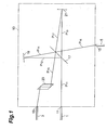
- FIG. 1 is a block diagram depicting the interleaver 10 according to the present embodiment.
- the interleaver 10 is comprised of a first port 11, second port 13, third port 15, half mirror 17, first reflecting mirror (total reflection mirror) 19, second reflecting mirror (total reflection mirror) 21, and a branching prism 23.
- the optical system including the first port 11, second port 13, third port 15, half mirror 17, first reflecting mirror 19 and second reflecting mirror 21, constitutes a Michelson interferometer.
- the half mirror 17 branches light, which reaches from the first port 11, into two, then outputs one light to the first reflecting mirror 19 and the other light to the second reflecting mirror 21.
- the half mirror 17 also branches the light, which is reflected by the first reflecting mirror 19 and reaches the half mirror 17, into two, then outputs one light to the second port 13 and the other light to the third port 15.
- the half mirror 17 also branches light, which is reflected by the second reflecting mirror 21 and reaches the half mirror 17, into two, then outputs one light to the second port 13 and the other light to the third port 15.
- the branching prism 23 is installed between the half mirror 17 and the second port 13, and outputs the light from the half mirror 17 to the second port 13 in a state where the space between the input optical axis from the first port 11 and the output optical axis to the second port 13 is spread.
- the optical axis from the half mirror 17 to the first reflecting mirror 19 (optical axis of the optical path P 12 ) and the reflected optical axis from the first reflecting mirror 19 (optical axis of the optical path P 14 ) cross at a predetermined angle greater than 0° (e.g. 0.8°)
- the output optical axis from the half mirror 17 to the second reflecting mirror 21 (optical axis of the optical path P 13 ) and the reflected optical axis from the second reflecting mirror 21 (optical axis of the optical path P 17 ) cross at a predetermined angle greater than 0° (e.g. 0.8°)
- the output optical axis to the first reflecting mirror 19 (optical axis of the optical path P 12 ) is set so as to cross with the reflecting face of the first reflecting mirror 19 at a predetermined angle other than 90° (e.g. 89.6°).
- the output optical axis to the second reflecting mirror 21 (optical axis of the optical path P 13 ) is set so as to cross with the reflecting face of the second reflecting mirror 21 at a predetermined angle other than 90° (e.g. 89.6°).
- the output optical axes from the half mirror 17 to the second port 13 and to the third port 15 are set so as to cross with the branching face of the half mirror 17 at a predetermined angle other than 45° (e.g. 44.2°).
- the input optical axis from the first port 11 to the half mirror 17 is set so as to cross with the branching face of the half mirror 17 at 45°.
- the output optical axes from the half mirror 17 to the second port 13 and to the third port 15 may be set so as to cross with the half mirror 17 at 45°, and the input optical axis from the first port 11 to the half mirror 17 (optical axis of the optical path P 11 ) maybe set so as to cross with the branching face of the half mirror 17 at the above mentioned predetermined angle other than 45°.
- the input optical axis from the first port 11 to the half mirror 17 (optical axis of the optical path P 11 ) and the output optical axes from the half mirror 17 to the second port 13 and to the third port 15 (optical axes of the optical paths P 15 and P 16 ) may be set so as to cross with the branching face of the half mirror 17 at a predetermined angle other than 45° respectively.
- the light which is input to the half mirror 17 by the optical path P 11 is branched into two by the half mirror 17, then one light is output to the optical path P 12 and the other light is output to the optical path P 13 .
- the light which is output from the half mirror 17 to the optical path P 12 is reflected by the first reflecting mirror 19, advances on the optical path P 14 to return to the half mirror 17, is branched into two by the half mirror 17, then one light is output to the optical path P 15 and the other light is output to the optical path P 16 .
- the light which is output from the half mirror 17 to the optical path P 13 is reflected by the second reflecting mirror 21, advances on the optical path P 17 to return to the half mirror 17, is branched into two by the half mirror 17, then one light is output to the optical path P 15 and the other light is output to the optical path P 16 .
- This interleaver 10 operates as follows.
- the light which is input to the first port 11 by the optical fiber 1 is output to the optical path P 11 .
- the light which is input to the half mirror 17 by the optical path P 11 is branched into two by the half mirror 17, and is output to the optical paths P 12 and P 13 .
- the light which is output to the optical path P 12 reaches to and is reflected back from the first reflecting mirror 19, and returns to the half mirror 17 by the optical path P 14 .
- the light which is input to the half mirror 17 by the optical path P 14 is branched into two by the half mirror 17, and is output to the optical paths P 15 and P 16 .
- the light which is output to the optical path P 13 reaches to and is reflected back from the second reflecting mirror 21, and returns to the half mirror 17 by the optical path P 17 .
- the light which is input to the half mirror 17 by the optical path P 17 is branched into two by the half mirror 17, and is output to the optical paths P 15 and P 16 .
- the light which is output from the half mirror 17 to the optical path P 15 is light where lights which reach the half mirror 17 by the optical path P 14 and the optical path P 17 respectively are partially super-imposed, and is output to the optical fiber 3 in a state where the space from the optical path P 11 (input optical axis) is spread by the branching prism 23.
- the light which is output from the half mirror 17 to the optical path P 16 is also light where lights which reach the half mirror 17 by the optical path P 14 and the optical path P 17 respectively are partially super-imposed, and is output to the optical fiber 5.
- the Michelson interferometer comprised of the optical system which includes the first port 11, second port 13, third port 15, half mirror 17, first reflecting mirror 19 and second reflecting mirror 21, has a transmission characteristic with a cycle according to the optical path length difference of the two optical paths.
- this interleaver 10 can input a signal light with multiband ( ⁇ 1 , ⁇ 2 , - - - , ⁇ 2n-1 , ⁇ 2n , - - - ) from the optical fiber 1, output the signal light with the first wavelength group ⁇ 1 ( ⁇ 1 , ⁇ 3 , - - - , ⁇ 2n-1 , - - - ) to the optical fiber 3, and output the signal light with the second wavelength group ⁇ 2 ( ⁇ 2 , ⁇ 4 , - - - ⁇ 2n , - - - ) to the optical fiber 5.
- the light which is input from the first port 11 is output to the second port 13 and to the third port 15 by the half mirror 17 and by the reflecting mirrors 19 and 21, included in the optical system which constitutes the Michelson interferometer, as mentioned above. Therefore it is possible to implement the interleaver 10 comprised of an optical system which does not need an optical circulator, so the interleaver 10 which is inexpensive, and with a less complex optical system is provided.
- FIG. 2 is a block diagram depicting the interleaver 30 according to the present embodiment.
- the interleaver 30 is comprised of a first port 31, second port 33, third port 35, half mirror 37, first reflecting mirror (total reflection mirror) 39, second reflecting mirror (total reflection mirror 41), dual collimator 43, and an optical axis correction section 45 (optical axis correction means).
- the optical system including the first port 31, second port 33, third port 35, half mirror 37, first reflecting mirror 39, and second reflecting mirror 41, constitute a Michelson interferometer.
- the half mirror 37 branches light, which reaches from the first port 31, into two, then outputs one light to the first reflecting mirror 39 and outputs the other light to the second reflecting mirror 41.
- the half mirror 37 also branches the light, which is reflected by the first reflecting mirror 39 and reaches the half mirror 37, into two, then outputs one light to the second port 33 and outputs the other light to the third port 35.
- the half mirror 37 branches the light, which is reflected by the second reflecting mirror 41 and reaches the half mirror 37, into two, then outputs one light to the second port 33 and outputs the other light to the third port 35.
- the first port 31 and the second port 33 are positioned at one end of the duel collimator 43.
- the optical axis correction section 45 is installed between the other end of the dual collimator 43 and the half mirror 37. This optical axis correction section 45 parallels the light which is output from the other end of the dual collimator 43 (input optical axis from the first port 31) and the light which is input to the other end of the dual collimator 43 (output optical axis to the second port 33), and includes a prism 47 and lens 49.
- the prism 47 and lens 49 are installed in the sequence of lens 49 and prism 47 viewed from the dual collimator 43 side.
- the prism 47 is for converting a state where the light, which is output from the other end of the dual collimator 43, and the light, which is input to the other end of the dual collimator 43, cross at a predetermined angle (e.g. 0.8°) into a state where the output light and the input light are parallel.
- a predetermined angle e.g. 0.8°
- the output optical axis from the half mirror 37 to the first reflecting mirror 39 (optical axis of the optical path P 32 ) and the reflected optical axis from the first reflecting mirror 39 (optical axis of the optical path P 34 ) cross at a predetermined angle greater than 0° (e.g. 0.8°)
- the output optical axis from the half mirror 37 to the second reflecting mirror 41 (optical axis of the optical path P 33 ) and the reflected optical axis from the second reflecting mirror 41 (optical axis of the optical path P 37 ) cross at a predetermined angle greater than 0° (e.g. 0.8°)
- the output optical axis to the first reflecting mirror 39 (optical axis of the optical path P 32 ) is set so as to cross with the reflecting face of the first reflecting mirror 39 at a predetermined angle other than 90° (e.g. 89.6°).
- the output optical axis to the second reflecting mirror 41 (optical axis of the optical path P 33 ) is set so as to cross with the reflecting face of the second reflecting mirror 41 at a predetermined angle other than 90° (e.g. 89.6°).
- the input optical axis from the first port 31 to the half mirror 37 (optical axis of the optical path P 31 ) is set so as to cross with the branching face of the half mirror 37 at a predetermined angle other than 45° (e.g. 44.6°)
- the output optical axes from the half mirror 37 to the second port 33 and to the third port 35 (optical axes of the optical paths P 35 and P 36 ) are set so as to cross with the branching face of the half mirror 37 at a predetermined angle other than 45° (e.g. 44.6°).
- the output optical axes from the half mirror 37 to the second port 33 and to the third port 35 may be set so as to cross the half mirror 37 at 45°
- the input optical axis from the first port 31 to the half mirror 37 (optical axis of the optical path P 31 ) may be set so as to cross with the branching face of the half mirror 37 at a predetermined angle other than 45°.
- the input optical axis from the first port 31 to the half mirror 37 may be set so as to cross with the half mirror 37 at 45°
- the output axes from the half mirror 37 to the second port 33 and to the third port 35 may be set so as to cross with the branching face of the half mirror 37 at a predetermined angle other than 45° respectively.
- the light which is input to the half mirror 37 by the optical path P 31 is branched into two by the half mirror 37, then one light is output to the optical path P 32 and the other light is output to the optical path P 33 .
- the light which is output from the half mirror 37 to the optical path P 32 is reflected by the first reflecting mirror 39, advances on the optical path P 34 to return to the half mirror 37, is branched into two by the half mirror 37, then one light is output to the optical path P 35 , and the other light is output to the optical path P 36 .
- the light which is output from the half mirror 37 to the optical path P 33 is reflected by the second reflecting mirror 41, advances on the optical path P 37 to return to the half mirror 37, is branched into two by the half mirror 37, then one light is output to the optical path P 35 , and the other light is output to the optical path P 36 .
- the interleaver 30 operates as follows.
- the light which is input to the first port 31 by the optical fiber 1 is output to the optical path P 31 via the dual collimator 43 and the optical axis correction section 45 (lens 49 and prism 47).
- the light which is input to the half mirror 37 by the optical path P 31 is branched into two by the half mirror 37, and is output to the optical paths P 32 and P 33 .
- the light which is output to the optical path P 32 reaches to and is reflected back from the first reflecting mirror 39, and returns to the half mirror 37 by the optical path P 34 .
- the light which is input to the half mirror 37 by the optical path P 34 is branched into two by the half mirror 37, and is output to the optical paths P 35 and P 36 .
- the light which is output to the optical path P 33 reaches to and is reflected back from the second reflecting light 41, and returns to the half mirror 37 by the optical path P 37 .
- the light which is input to the half mirror 37 by the optical path P 37 is branched into two by the half mirror 37, and is output to the optical paths P 35 and P 36 .
- the light which is output from the half mirror 37 to the optical path P 35 is light where lights which reach the half mirror 37 by the optical path P 34 and the optical path P 37 respectively are partially super-imposed, and is output to the optical fiber 3 via the optical axis correction section 45 and the dual collimator 43.
- the light which is output from the half mirror 37 to the optical path P 36 is also light where lights which reach the half mirror 37 by the optical path P 34 and the optical path P 37 respectively are partially super-imposed, and is output to the optical fiber 5.
- the Michelson interferometer comprised of the optical system, which includes the first port 31, second port 33, third port 35, and half mirror 37, first reflecting mirror 39 and second reflecting mirror 41, has a transmission characteristic with a cycle according to the optical path length difference of the two optical paths.
- this interleaver 30 can input the signal light with multiband ( ⁇ 1 , ⁇ 2 , - - - , ⁇ 2n-1 , ⁇ 2n , - - - ) by the optical fiber, separate the signal light, output the signal light with the first wavelength group ⁇ 1 ( ⁇ 1 , ⁇ 3 , - - - , ⁇ 2n-1 , - - - ) to the optical fiber, and output the signal light with the second wavelength group ⁇ 2 ( ⁇ 2 , ⁇ 4 , - - - , ⁇ 2n , - - - ) to the optical fiber.
- the light which is input from the first port 31 is output to the second port 33 and the third port 35 by the half mirror 37 and the reflecting mirrors 39 and 41, which are included in the optical system constituting the Michelson interferometer, as mentioned above. Therefore it is possible to implement the interleaver 30 comprised of an optical system which does not need an optical circulator, so the interleaver 30 is which inexpensive, and with a less complex optical system is provided.
- the input optical axis from the first port 31 and the output optical axis to the second port 33 are paralleled by the optical axis correction section 45, so the occurrence of the loss of light which is input from the optical fiber 1 to the first port 31 and the light which is output from the second port 33 to the optical fiber 3 can be controlled.
- a Gires-Tournois resonator which includes a semi-transparent mirror, which transmittance is several tens %, and a total reflection mirror, may be used as one reflecting mirror.
- Figs. 3A and 3B are block diagrams depicting the interleaver 10 according to the present embodiment.
- the optical system (optical path) shown in Fig. 3A and the optical system (optical path) shown in Fig. 3B are positioned at the top and bottom of each other in a direction vertical to the page face.
- the interleaver 210 is comprised of a first port 211, second port 213, third port 215, half mirror 217, first reflecting mirror (total reflection mirror) 219, second reflecting mirror (total reflection mirror) 221, branching prism 223, polarization separation element 225, wavelength plate 227, polarization combining element 229, wavelength plate 231, polarization combining element 233, and a wavelength plate 235.
- the optical system including the first port 211, second port 213, third port 215, half mirror 217, first reflecting mirror 219 and the second reflecting mirror 221, constitutes a Michelson interferometer.
- the half mirror 217 branches light, which reaches from the first port 211, into two, then outputs one light to the first reflecting mirror 219, and the other light to the second reflecting mirror 221.
- the half mirror 217 also branches the light, which is reflected by the first reflecting mirror 219 and reaches the half mirror 217, into two, then outputs one light to the second port 213, and the other light to the third port 215.
- the half mirror 217 also branches light, which is reflected by the second reflecting mirror and reaches the half mirror 217, into two, then outputs one light to the second port 213, and the other light to the third port 215.
- the branching prism 223 is installed between the half mirror 217 and the second port 213, and outputs the light from the half mirror 217 to the second port 213 in a state where the space between the input optical axis from the first port 211 and the output optical axis to the second port 213 is spread.
- the polarization separation element 225 is comprised of a double refraction material installed between the first port 211 and the half mirror 217, separates the light which reaches from the first port 211 into two lights having polarization planes perpendicular to each other, then outputs one light, that is light with the first polarization component, to the optical path P 211 , and outputs the other light, that is light with the second polarization component, which is perpendicular to the light with the first polarization component, to the optical path P 221 .
- the optical path P 211 and the optical path P 221 are positioned at the top and bottom of each other in a direction vertical to the page face in Fig. 3A and 3B.
- the wavelength plate (polarization plane paralleling element) 227 is installed on the optical path P 211 between the polarization separation element 225 and the half mirror 217, rotates the polarization plane of light with the first polarization component, which is output from the polarization separation element 225 to the optical path P 211 , by 90°, and outputs this light as the light with the second polarization component.
- this wavelength plate 227 parallels the polarization planes of the two lights having polarization planes perpendicular to each other, which are output from the polarization separation element 225 to the optical paths P 211 and P 221 , and outputs these parallel lights to the half mirror 217 respectively.
- Fig. 3A shows, the light which is input to the half mirror 217 by the optical path P 211 is branched into two by the half mirror 217, then one light is output to the optical path P 212 , and the other light is output to the optical path P 213 .
- the light which is output from the half mirror 217 to the optical path P 212 is reflected by the first reflecting mirror 219, advances on the optical path P 214 to return to the half mirror 217, is branched into two by the half mirror 217, then one light is output to the optical path P 215 , and the other light is output to the optical path P 216 .
- the light which is output from the half mirror 217 to the optical path P 213 is reflected by the second reflecting mirror 221, advances on the optical path P 217 to return to the half mirror 217, is branched into two by the half mirror 217, then one light is output to the optical path P 215 , and the other light is output to the optical path P 216 . During this propagation, the light remains as light with the second polarization component.
- Fig. 3B shows, the light which is input to the half mirror 217 by the optical path P 221 is branched into two by the half mirror 217, then one light is output to the optical path P 222 , and the other light is output to the optical path P 223 .
- the light which is output from the half mirror 217 to the optical path P 222 is reflected by the first reflecting mirror 219, advances on the optical path P 224 to return to the half mirror 217, is branched into two by the half mirror 217, then one light is output to the optical path P 225 , and the other light is output to the optical path P 226 .
- the light which is output from the half mirror 217 to the optical path P 23 is reflected by the second reflecting mirror 221, advances on the optical path P 227 to return to the half mirror 217, is branched into two by the half mirror 217, then one light is output to the optical path P 225 , and the other light is output to the optical path P 226 . During this propagation, the light remains as light with the second polarization component.
- the wavelength plate (polarization plane orthogonalizing element) 231 is installed on the optical path P 225 between the half mirror 217 and the second port 213, rotates the polarization plane of the light with the second polarization component, which is output from the half mirror 217 to the optical path P 225 , by 90°, and outputs this light as light with the first polarization component.
- this wavelength plate 231 inputs the two lights having polarization planes parallel to each other, which are output from the half mirror 217 to the optical paths P 215 and P 225 , orthogonalizes the polarization planes of each light, and outputs these orthogonalizing lights to the second port 213 respectively.
- the polarization combining element 229 is comprised of a double refraction material installed between the wavelength plate 231 and the second port 213, inputs the two lights having polarization planes which are orthogonalized by the wavelength plate 231, combines the polarization of these lights, and outputs this light to the second port 213.
- the wavelength plate (polarization plane orthogonalizing element) 235 is installed on the optical path P 226 between the half mirror 217 and the third port 215, rotates the polarization plane of the light with the second polarization component, which is output from the half mirror 217 to the optical path P 226 , by 90°, and outputs this light as light with the first polarization component.
- this wavelength plate 235 inputs the two lights having polarization planes parallel to each other, which are output from the half mirror 217 to the optical paths P 216 and P 226 , orthogonalizes the polarization planes of each light, and outputs these orthogonalized lights to the third port 215 respectively.
- the polarization combining element 233 is comprised of a double refraction material installed between the wavelength plate 235 and the third port 215, inputs the two lights having polarization planes, which are orthogonalized by the wavelength plate 235, combines the polarization of these lights, and outputs this light to the third port 215.
- the output optical axes from the half mirror 217 to the first reflecting mirror 219 (optical axis of the optical path P 212 and optical axis of the optical path P 222 ) and the reflected optical axes from the first reflecting mirror 219 (optical axis of the optical path P 214 and optical axis of the optical path P 224 ) cross at a predetermined angle greater than 0°, (e.g.
- the optical axes from the half mirror 217 to the second reflecting mirror 221 (optical axis of the optical path P 213 and optical axis of the optical path P 223 ) and the reflected optical axes from the second reflecting mirror 221 (optical axis of the optical path P 217 and optical axis of the optical path P 227 ) cross at a predetermined angle greater than 0° (e.g. 0.3°), so that the input optical axis from the first port 211 and the output optical axis to the second port 213 become different when the light is output to the second port 213.
- the output optical axes to the first reflecting mirror 219 are set so as to cross with the reflecting face of the first reflecting mirror 219 at a predetermined angle other than 90 (e.g.
- the output optical axes to the second reflecting mirror 221 are set so as to cross with the reflecting face of the second reflecting mirror 221 at a predetermined angle other than 90° (e.g. 89.7°).
- the output optical axes from the half mirror 217 to the second port 213 and the third port 215 are set so as to cross with the branching face of the half mirror 217 at a predetermined angle other than 45° (e.g. 44.7°).
- the input optical axes from the first port 211 to the half mirror 217 are set so as to cross with the branching face of the half mirror 217 at 45°.
- the output optical axes from the half mirror 217 to the second port 213 and the third port 215 may be set so as to cross with the half mirror 217 at 45°
- the input optical axes from the first port 211 to the half mirror 217 may be set so as to cross with the branching face of the half mirror 217 at the above mentioned predetermined angle other than 45°.
- the input optical axes from the first port 211 to the half mirror 217 (optical axis of the optical path P 211 and optical axis of the optical path P 221 ) and the output optical axes from the half mirror 17 to the second port 213 and the third port 215 (optical axes of the optical paths P 215 and P 216 and optical axes of the optical paths P 225 and P 226 ) may be set so as to cross with the branching face of the half mirror 217 at a predetermined angle other than 45° respectively.
- This interleaver 210 operates as follows.
- the light which is input from the optical fiber 201 to the first port 211 is polarization-separated by the polarization separation element 225, then light with the first polarization component is output to the optical path P 211 , and light with the second polarization component is output to the optical path P 221 .
- the light with the first polarization component, which is output from the polarization separation element 225 to the optical path P 211 is converted into the light with the second polarization component by the wavelength plate 227.
- the light which is input from the optical path P 211 to the half mirror 217 is branched into two by the half mirror 217, and is output to the optical paths P 212 and P 213 .
- the light, which is output to the optical path P 212 reaches to and is reflected from the first reflecting mirror 219, and returns to the half mirror 217 by the optical path P 214 .
- the light which is input to the half mirror 217 by the optical path P 214 is branched into two by the half mirror 217, and is output to the optical paths P 215 and P 216 .
- the light which is output to the optical path P 213 reaches to and is reflected by the second reflecting mirror 221, and returns to the half mirror 217 by the optical path P 217 .
- the light which is input to the half mirror 217 by the optical path P 217 is branched into two by the half mirror 217, and is output to the optical paths P 215 and P 216 . During this propagation, the lights remains as the light with the second polarization component.
- the light which is input to the half mirror 217 by the optical path P 221 is branched into two by the half mirror 217, and is output to the optical paths P 222 and P 223 .
- the light which is output to the optical path P 222 reaches to and is reflected from the first reflecting mirror 219, and returns to the half mirror 217 by the optical path P 224 .
- the light which is input to the half mirror 217 by the optical path P 224 is branched into two by the half mirror 217, and is output to the optical paths P 225 and P 226 .
- the light which is output to the optical path P 223 reaches to and is reflected from the second reflecting mirror 221, and returns to the half mirror 217 by the optical path P 227 .
- the light which is input to the half mirror 217 by the optical path P 227 is branched into two by the half mirror 217, and is output to the optical paths P 225 and P 226 . During this propagation, the light remains as light with the second polarization component.
- the light with the secondpolarization component, which is output from the half mirror 217 to the optical path P 215 is light where lights which reach the half mirror 217 by the optical path P 214 and optical path P 217 respectively are partially super-imposed.
- the light with the second polarization component, which is output from the half mirror 217 to the optical path P 225 is light where lights which reach the half mirror 217 from the optical path P 224 and optical path P 227 respectively are partially super-imposed.
- the light with the second polarization component, which is output from the half mirror 217 to the optical path P 225 is converted into the light with the first polarization component by the wavelength plate 231.
- the light with the second polarization component, which is output from the half mirror 217 to the optical path P 216 is light where lights which reach the half mirror 217 by the optical path P 214 and optical path P 217 respectively are partially super-imposed.
- the light with the second polarization component, which is output from the half mirror 217 to the optical path P 226 is light where lights which reach the half mirror 217 by the optical path P 224 and optical path P 227 respectively are partially super-imposed.
- the light with the second polarization component, which is output from the half mirror 217 to the optical path P 226 is converted into light with the first polarization component by the wavelength plate 235.
- the light on the optical path P 226 which is converted into light with the first polarization component by the wavelength plate 235 and the light with the second polarization component, which is output from the half mirror 217 to the optical path P 216 , are polarization-combined by the polarization combining element 233. This light, after the polarization-combining, is output to the optical fiber 205.
- the Michelson interferometer comprised of the optical system, which includes the first port 211, second port 213, third port 215, half mirror 217, first reflecting mirror 219 and the second reflecting mirror 221, has a transmission characteristic with a cycle according to the optical path length difference of the two optical paths.
- this interleaver 210 can input the signal light with multiband ( ⁇ 1 , ⁇ 2 , - - - , ⁇ 2n-1 , ⁇ 2n , - - - ) by the optical fiber 201, separate the signal light, output the signal light with the first wavelength group ⁇ 1 ( ⁇ 1 , ⁇ 3 , - - - , ⁇ 2n-1 , - - - ) to the optical fiber 203, and output the signal light with the second wavelength group ⁇ 2 ( ⁇ 2 , ⁇ 4 , - - - , ⁇ 2n , - - - ) to the optical fiber 205.
- the polarization state of the light when entering the half mirror 217, first reflecting mirror 219 and the second reflecting mirror 221 respectively, is constant, regardless the polarization state of the light which is input by the optical fiber 201. Therefore the transmission characteristic of light in the first wavelength area ⁇ 1 from the optical fiber 201 to the optical fiber 203, and the transmission characteristic of light in the second wavelength area ⁇ 2 from the optical fiber 201 to the optical fiber 205, have a polarization dependency which is controlled respectively.
- the light which is input from the first port 211, is output to the second port 213 and the third port 215 by the half mirror 217 and the reflecting mirrors 219 and 221, which are included in the optical system constituting the Michelson interferometer, as mentioned above. Therefore it is possible to implement the interleaver 210 comprised of an optical system which does not need an optical circulator, so the interleaver 210 which is inexpensive and with a less complex optical system is provided.
- FIGs. 4A and 4B are block diagrams depicting the interleaver 240 according to the present embodiment.
- the optical system (optical path) shown in Fig. 4A and the optical system (optical path) shown in Fig. 4B are positioned at the top and bottom of each other in a direction vertical to the page face.
- the interleaver 240 is comprised of a first port 241, second port 243, third port 245, half mirror 247, first reflecting mirror (total reflection mirror) 249, second reflecting mirror (total reflection mirror) 251, dual collimator 253 and an optical axis correction section 255 (optical axis correction means).
- the optical system including the first port 241, second port 243, third port 245, half mirror 247, first reflecting mirror 249 and second reflecting mirror 251, constitutes the Michelson interferometer.
- the half mirror 247 branches the light, which reaches from the first port 241, into two, then outputs one light to the first reflecting mirror 249, and outputs the other light to the second reflecting mirror 251.
- the half mirror 247 also branches the light, which is reflected by the first reflecting mirror 249 and reaches the half mirror 247, into two, then outputs one light to the second port 243, and outputs the other light to the third port 245.
- the half mirror 247 also branches light, which is reflected by the second reflecting mirror 251 and reaches the half mirror 247, into two, then outputs one light to the second port 243, and outputs the other light to the third port 245.
- the first port 241 and the second port 243 are positioned at one end of the dual collimator 253.
- the optical axis correction section 255 is installed between the other end of the dual collimator 253 and the half mirror 247.
- This optical axis correction section 255 parallels the light which is output from the other end of the dual collimator 253 (input optical axis of the first port 241) and the light which is input to the other end of the dual collimator 253 (output optical axis to the second port 243), and includes a prism 257 and a lens 259.
- the prism 257 and lens 259 are installed in the sequence of the lens 259 and prism 257 viewed from the dual collimator 253 side.
- the prism 257 is for converting a state where the light which is output from the other end of the dual collimator 253 and the light which is input to the other end of the dual collimator 253 cross at a predetermined angle (e.g. 0.3°) into a state where the output light and the input light are parallel.
- a predetermined angle e.g. 0.3°
- the polarization separation element 261 is comprised of a double refraction material installed between the first port 241 and the half mirror 247, separates the light which reaches from the first port 241 into two lights having polarization planes perpendicular to each other, then outputs one light, that is light with the first polarization component, to the optical path P 241 , and outputs the other light, that is light with the second polarization component, which is perpendicular to the light with the first polarization component, to the optical path P 251 .
- the optical path P 241 and the optical path P 251 are positioned at the top and bottom of each other in a direction vertical to the page face in Figs. 4A and 4B.
- the wavelength plate (polarization paralleling element) 263 is installed on the optical path P 241 between the polarization separation element 261 and the half mirror 247, rotates the polarization plane of the light with the first polarization component, which is output from the polarization separation element 261 to the optical path P 241 , by 90°, and outputs this light as the light with the second polarization component.
- this wavelength plate 263 parallels the polarization planes perpendicular to each other, which are output from the polarization separation element 261 to the optical paths P 241 and P 251 , and outputs the paralleled lights to the half mirror 247 respectively.
- Fig. 4A shows, the light, which is input to the half mirror 247 by the optical path P 241 , is branched into two by the half mirror 247, then one light is output to the optical path P 242 , and the other light is output to the optical path P 243 .
- the light which is output from the half mirror 247 to the optical path P 242 is reflected by the first reflecting mirror 249, advances on the optical path P 244 to return to the half mirror 247, is branched into two by the half mirror 247, then one light is output to the optical path P 245 , and the other light is output to the optical path P 246 .
- the light which is output from the half mirror 247 to the optical path P 243 is reflected by the second reflecting mirror 251, advances on the optical path P 247 to return to the half mirror 247, is branched into two by the half mirror 247, then one light is output to the optical path P 245 , and the other light is output to the optical path P 246 . During this propagation, the light remains as light with the second polarization component.
- Fig. 4B shows, the light, which is input to the half mirror 247 by the optical path P 251 , is branched into two by the half mirror 247, then one light is output to the optical path P 252 , and the other light is output to the optical path P 253 .
- the light which is output from the half mirror 247 to the optical path P 252 is reflected by the first reflecting mirror 249, advances on the optical path P 254 to return to the half mirror 247, is branched into two by the half mirror 247, then one light is output to the optical path P 255 , and the other light is output to the optical path P 256 .
- the light which is output from the half mirror 247 to the optical path P 253 is reflected by the second reflecting mirror 251, advances on the optical path P 257 to return to the half mirror 247, is branched into two by the half mirror 247, then one light is output to the optical path P 255 , and the other light is output to the optical path P 256 . During this propagation, the light remains as light with the second polarization component.
- the wavelength plate (polarization plane orthogonalizing element) 267 is installed on the optical path P 255 between the half mirror 247 and the second port 243, rotates the polarization plane of the light with the second polarization element, which is output from the half mirror 247 to the optical path P 255 , by 90°, and outputs this light as the light with the first polarization component.
- this wavelength plate 267 inputs the two lights having polarization planes parallel to each other, which are output from the half mirror 247 to the optical paths P 245 and P 255 , orthogonalizes the polarization planes of each light, and outputs these orthogonalized lights to the optical axis correction section 255 (second port 243) respectively.
- the polarization combining element 265 is comprised of a double refraction material installed between the wavelength plate 267 and the second port 243, inputs the two lights having polarization planes which are orthogonalized by the wavelength plate 267, combines the polarization of these lights, and outputs this light to the optical axis correction section 255 (second port 243).
- the wavelength plate (polarization plane orthogonalizing element) 271 is installed on the optical path P 256 between the half mirror 247 and the third port 245, rotates the polarization plane of the light with the second polarization component, which is output from the half mirror 247 to the optical path P 256 , by 90°, and outputs this light as the light with the first polarization component.
- this wavelength plate 271 inputs the two lights having polarization planes parallel to each other, which are output from the half mirror 247 to the optical path P 246 and P 256 , orthogonalizes the polarization planes of each light, and outputs these orthogonalized lights to the third port 245 respectively.
- the polarization combining element 269 is comprised of a double refraction material installed between the wavelength plate 271 and the third port 245, inputs the two lights having polarization planes which are orthogonalized by the wavelength plate 271, combines the polarization of these lights, and outputs this light to the third port 245.
- the output optical axes from the half mirror 247 to the first reflecting mirror 249 (optical axis of the optical path P 242 and optical axis of the optical path P 252 ) and the reflected optical axes from the first reflecting mirror 249 (optical axis of the optical path P 244 and optical axis of the optical path P 255 ) cross at a predetermined angle greater than 0° (e.g.
- the output optical axes from the half mirror 247 to the second reflecting mirror 251 (optical axis of the optical path P 243 and optical axis of the optical path P 255 ) and the reflected optical axes from the second reflecting mirror 251 (optical axis of the optical path P 247 and optical axis of the optical path P 257 ) cross at a predetermined angle greater than 0° (e.g. 0.3°), so that the input optical axis from the first port 241 and the output optical axis to the second port 243 become different when the light is output to the second port 243.
- the output optical axes to the first reflecting mirror 249 are set so as to cross with the reflecting face of the first reflecting mirror 249 at a predetermined angle other than 90° (e.g.
- the output optical axes to the second reflecting mirror 251 are set so as to cross with the reflecting face of the second reflecting mirror 251 at a predetermined angle other than 90° (e.g. 89.7°).
- the input axes from the first port 241 to the half mirror 247 are set so as to cross with the branching face of the half mirror 247 at a predetermined angle other than 45° (e.g. 44.7°)
- the output axes from the half mirror 247 to the second port 243 and the third port 245 are set so as to cross with the branching face of the half mirror 247 at a predetermined angle other than 45° (e.g. 44.7°).
- the output optical axes from the half mirror 247 to the second port 243 and the third port 245 may be set so as to cross with the half mirror 247 at 45°
- the input optical axes from the first port 241 to the half mirror 247 may be set so as to cross with the branching face of the half mirror 247 at a predetermined angle other than 45°.
- the input optical axes from the first port 241 to the half mirror 247 may be set so as to cross with the half mirror 247 at 45°
- the output optical axes from the half mirror 247 to the second port 243 and the third port 245 may be set so as to cross with the branching face of the half mirror 247 at a predetermined angle other than 45° respectively.
- This interleaver 210 operates as follows.
- the light which is input from the optical fiber 201 to the first port 241 is polarization-separated by the polarization separation element 261 via the dual collimator 253 and the optical axis correction section 255 (lens 259 and prism 257), then light with the first polarization component is output to the optical path P 241 , and light with the second polarization component is output to the optical path P 251 .
- the light with the first polarization component, which is output from the polarization separation element 261 to the optical path P 241 is converted into the light with the second polarization component by the wavelength plate 263.
- the light which is output to the optical path P 242 reaches to and is reflected from the first reflecting mirror 249, and returns to the half mirror 247 by the optical path P 244 .
- the light, which is input to the half mirror 247 by the optical path P 244 is branched into two by the half mirror 247, and is output to the optical paths P 245 and P 246 .
- the light which is output to the optical path P 243 reaches to and is reflected from the second reflecting mirror 251, and returns to the half mirror 247 by the optical path P 247 .
- the light which is input to the half mirror 247 by the optical path P 247 , is branched into two by the half mirror 247, and is output to the optical paths P 245 and P 246 . During this propagation, the light remains as light with the second polarization component.
- the light which is output to the optical path P 252 reaches to and is reflected from the first reflecting mirror 249, and returns to the half mirror 247 by the optical path P 254 .
- the light which is input to the half mirror 247 by the optical path P 254 is branched into two by the half mirror 247, and is output to the optical paths P 255 and P 256 .
- the light which is output to the optical path P 253 reaches to and is reflected from the second reflecting mirror 251, and returns to the half mirror 247 by the optical path P 257 .
- the light which is input to the half mirror 247 by the optical path P 257 , is branched into two by the half mirror 247, and is output to the optical paths P 255 and P 256 . During this propagation, the light remains as the light with the second polarization component.
- the light with the secondpolarization component, which is output from the half mirror 247 to the optical path P 245 is light where lights which reach the half mirror 247 from the optical path P 244 and the optical path P 247 respectively are partially super-imposed.
- the light with the second polarization component, which is output from the half mirror 247 to the optical path P 255 is light where lights which reach the half mirror 247 by the optical path P 254 and the optical path P 257 respectively are partially super-imposed.
- the light with the second polarization component, which is output from the half mirror 247 to the optical path P 255 is converted into the light with the first polarization component by the wavelength plate 267.
- the light on the optical path P 255 which is converted into the light with the first polarization component by the wavelength plate 267, and the light with the second polarization component which is output from the half mirror 247 to the optical path P 245 , are polarization-combined by the polarization combining element 265.
- This light after the polarization combining, is output to the optical fiber 203 via the optical axis correction section 255 and the dual collimator 253.
- the light with the secondpolarization component, which is output from the half mirror 247 to the optical path P 246 is light where lights which reach the half mirror 247 by the optical path P 244 and the optical path P 247 respectively are partially super-imposed.
- the light with the second polarization component, which is output from the half mirror 247 to the optical path P 256 is light where lights which reach the half mirror 247 by the optical paths P 254 and P 257 respectively are super-imposed.
- the light with the second polarization component, which is output from the half mirror 247 to the optical path P 256 is converted into light with the first polarization component by the wavelength plate 271.
- the light on the optical path P 256 which is converted into the light with the first polarization component by the wavelength plate 271, and the light with the second polarization component, which is output from the half mirror 247 to the optical path P 246 , are polarization-combined by the polarization combining element 269. This light, after the polarization combining, is output to the optical fiber 205.
- the Michelson interferometer comprised of the optical system, which includes the first port 241, second port 243, third port 245, half mirror 247, first reflecting mirror 249 and the second reflecting mirror 251, has a transmission characteristic with a cycle according to the optical path length difference of the two optical paths.
- this interleaver 240 can input the signal light with multiband ( ⁇ 1 , ⁇ 2 , - - - , ⁇ 2n-1 , ⁇ 2n , - - - ) by the optical fiber 201, separate the signal light, output the signal light with the first wavelength group ⁇ 1 ( ⁇ 1 , ⁇ 3 , - - - , ⁇ 2n-1 , - - - ) to the optical fiber, and output the signal light with the second wavelength group ⁇ 2 ( ⁇ 2 , ⁇ 4 , - - - , ⁇ 2n , - - - ) to the optical fiber 205.
- the polarization state of the light when entering the half mirror, first reflecting mirror 249 and the second reflecting mirror 251 respectively, is constant, regardless the polarization state of the light which is input from the optical fiber 201. Therefore the transmission characteristic of the light in the first wavelength area ⁇ 1 from the optical fiber 201 to the optical fiber 203, and the transmission characteristic of the light in the second wavelength area ⁇ 2 from the optical fiber 201 to the optical fiber 205, have a polarization dependency, which is controlled respectively.
- the light which is input from the first port 241, is output to the second port 243 and the third port 245 by the half mirror 247 and the reflecting mirrors 249 and 251, which are included in the optical system constituting the Michelson interferometer, as mentioned above. Therefore it is possible to implement the interleaver 240 comprised of an optical system which does not need an optical circulator, so the interleaver 240 which is inexpensive and with a less complex optical system is provided.
- the input optical axis from the first port 241 is paralleled with the output optical axis to the second port 243 by the optical axis correction section 255, so the loss which occurs to the light to be input from the optical fiber 201 to the first port 241 and the light to be output from the second port 243 to the optical fiber 203 can be controlled.
- FIGs. 5A and 5B are block diagrams depicting the interleaver 280 according to the present embodiment.
- the optical system (optical path) shown in Fig. 5A and the optical system (optical path) shown in Fig. 5 B are positioned at the top and bottom of each other in a direction vertical to the page face.
- the interleaver 280 is comprised of a first port 281, second port 283, third port 285, half mirror 287, first reflecting mirror (total reflection mirror) 289, second reflecting mirror (total reflection mirror) 291, branching prism 293 and a polarization separation element 295.
- the optical system including the first port 281, second port 283, third port 285, half mirror 287, first reflecting mirror 289 and second reflecting mirror 291, constitutes a Michelson interferometer.
- the half mirror 287 branches the light, which reaches from the first port 281, into two, then outputs one light to the first reflecting mirror 289, and outputs the other light to the second reflecting mirror 291.
- the half mirror 287 also branches the light, which is reflected by the first reflecting mirror 289, into two, then outputs one light to the second port 283, and outputs the other light to the third port 285.
- the branching prism 293 is installed between the half mirror 287 and the second port 283, and outputs the light from the half mirror 287 to the second port 283 in a state where the space between the input optical axis from the first port 281 and the output optical axis to the second port 283 is spread.
- the polarization separation element 295 is comprised of a double refraction material installed between the first port 281 and the half mirror 287, separates the light which reaches from the first port 281 into two lights having polarization planes perpendicular to each other, then outputs one light, that is the light with the first polarization component, to the optical path P 281 , and outputs the other light, that is the light with the second polarization component, which is perpendicular to the light with the first polarization component, to the optical path P 291 .
- the optical path P 281 and the optical path P 291 are positioned at the top and bottom of each other in a direction vertical to the page face in Figs. 3A and 3B.
- Fig. 5A shows, the light, which is input to the half mirror 287 by the optical path P 281 , is branched into two by the half mirror 287, then one light is output to the optical path P 282 , and the other light is output to the optical path P 283 .
- the light, which is output from the half mirror 287 to the optical path P 282 is reflected by the first reflecting mirror 289, advances on the optical path P 284 to return to the half mirror 287, is branched into two by the half mirror 287, then one light is output to the optical path P 285 , and the other light is output to the optical path P 286 .
- the light which is output to the optical path P 285 is output to the second port 283. During this propagation, the light remains as light with the first polarization component.
- the light which is output to the optical path P 286 is dropped.
- Fig. 5B shows, the light, which is input to the half mirror 287 by the optical path P 291 , is branched into two by the half mirror 287, then one light is output to the optical path P 292 , and the other light is output to the optical path P 293 .
- the light, which is output from the half mirror 287 to the optical path P 292 is reflected by the first reflecting mirror 289, advances on the optical path P 294 to return to the half mirror 287, is branched into two by the half mirror 287, then one light is output to the optical path P 295 , and the other light is output to the optical path P 296 .
- the light, which is output to the optical path P 296 is output to the third port 285. During this propagation, the light remains as light with the second polarization component.
- the light which is output to the optical path P 295 is dropped.
- the output optical axes from the half mirror 287 to the first reflecting mirror 289 (optical axis of the optical path P 282 and optical axis of the optical path P 292 ) and the reflected optical axes from the first reflecting mirror 281 (optical axis of the optical path P 284 and optical axis of the optical path P 294 ) cross at a predetermined angle greater than 0° (e.g.
- the output optical axes from the half mirror 287 to the second reflecting mirror 291 (optical axis of the optical path P 283 and optical axis of the optical path P 293 ) and the reflected optical axes from the second reflecting mirror 291 (optical axis of the optical path P 287 and optical axis of the optical path P 297 ) cross at a predetermined angle greater than 0° (e.g. 0.3°), so that the input optical axis from the first port 281 and the output optical axis to the second port 283 become different when the light is output to the second port 283.
- the output axes of the first reflecting mirror 289 (optical axis of the optical path P 282 and optical axis of the optical path P 292 ) are set so as to cross with the reflecting face of the first reflecting mirror 289 at a predetermined angle other than 90° (e.g.
- the output optical axes to the second reflecting mirror 291 are set so as to cross with the reflecting face of the second reflecting mirror 291 at a predetermined angle other than 90° (e.g. 89.7°).
- the output optical axes from the half mirror 287 to the second port 283 and the third port 285 are set so as to cross with the branching face of the half mirror 287 at a predetermined angle other than 45° (e.g. 44.7°).
- the input axes from the first port 281 to the half mirror 287 are set so as to cross with the branching face of the half mirror 287 at 45°.
- the output optical axes from the half mirror 287 to the second port 283 and the third port 285 may be set so as to cross with the half mirror 287 at 45°
- the input optical axes from the first port 281 to the half mirror 287 (optical axis of the optical path P 81 and optical axis of the optical path P 291 ) may be set so as to cross with the branching face of the half mirror 287 at the above mentioned predetermined angle other than 45°.
- the input optical axes from the first port 281 to the half mirror 287 (optical axis of the optical path P 281 and optical axis of the optical path P 291 ) and the output optical axes from the half mirror 287 to the second port 283 and the third port 285 (optical axis of the optical path P 285 and optical axis of the optical path P 296 ) may be set so as to cross with the branching face of the half mirror 287 at a predetermined angle other than 45° respectively.
- This interleaver 280 operates as follows. The light which is input from the optical fiber 201 to the first port 281 is polarization-separated by the polarization separation element 295, then light with the first polarization component is output to the optical path P 281 , and the light with the second polarization component is output to the optical path P 291 .
- the light which is output to the optical path P 282 reaches to and is reflected from the first reflecting mirror 289, and returns to the half mirror 287 by the optical path P 284 .
- the light, which is input to the half mirror 287 by the optical path P 284 is branched into two by the half mirror 287, and is output to the optical paths P 285 and P 286 .
- the light which is output to the optical path P 283 reaches to and is reflected from the second reflecting mirror 291, and returns to the half mirror 287 by the optical path P 287 .
- the light which is input to the half mirror 287 by the optical path P 287 , is branched into two by the half mirror 287, and is output to the optical paths P 285 and P 286 . During this propagation, the light remains as light with the first polarization component.
- the light which is output to the optical path P 292 reaches to and is reflected from the first reflecting mirror 289, and returns to the half mirror 287 by the optical path P 294 .
- the light, which is input to the half mirror 287 by the optical path P 294 is branched into two by the half mirror 287, and is output to the optical paths P 295 and P 296 .
- the light which is output to the optical path P 293 reaches to and is reflected from the second reflecting mirror 291, and returns to the half mirror 287 by the optical path P 297 .
- the light which is input to the half mirror 287 by the optical path P 297 , is branched into two by the half mirror 287, and is output to the optical paths P 295 and P 296 . During this propagation, the light remains as light with the second polarization component.
- the light with the first polarization component, which is output from the half mirror 287 to the optical path P 285 is light where lights which reach the half mirror 287 by the optical path P 284 and the optical path P 287 respectively are partially super-imposed.
- the light with the first polarization component, which is output from the half mirror 287 to the optical path P 285 is output to the optical fiber 203 in a state where the space from the optical path P 281 (input optical axis) is spread by the branching prism 293.
- the light with the second polarization component which is output from the half mirror 287 to the optical path P 296 , is light where lights which reach the half mirror 287 by the optical path P 294 and the optical path P 297 respectively are partially super-imposed.
- the light with the second polarization component which is output from the half mirror 287 to the optical path P 295 , is output to the optical fiber 205.
- the Michelson interferometer comprised of the optical system, which includes the first port 281, second port 283, third port 285, half mirror 287, first reflecting mirror 289, and the second reflecting mirror 291, has a transmission characteristic with a cycle according to the optical path length difference of the two optical paths.
- this interleaver 280 can input the signal light with multiband ( ⁇ 1 , ⁇ 2 , - - - , ⁇ 2n-1 , ⁇ 2n , - - - ) by the optical fiber 201, separate the signal light, output the signal light with the first wavelength group ⁇ 1 ( ⁇ , ⁇ 2 , - - - , ⁇ 2-1 , - - - ) to the optical fiber 203, and output the signal light with the second wavelength group ⁇ 2 ( ⁇ 2 , ⁇ 4 , - - - , ⁇ 2n , - - - ) to the optical fiber 205.
- the optical system constituting the above mentioned Michelson interferometer is configured so as to output one of the two lights having polarization planes perpendicular to each other, which is output from the polarization separation element 295 (light with first polarization component) to the second port 283, and output the other light (light with second polarization component) to the third port 285. Therefore the interleaver 280 is a polarization interleaver.
- the light which is output from the first port 281 is output to the second port 283 and the third port 285 by the half mirror 287 and the reflecting mirrors 289 and 291, which are included in the optical system constituting the Michelson interferometer. Therefore an interleaver with an optical system which does not need an optical circulator can be implemented, so the interleaver which is inexpensive and with a less complex optical system is provided.
- FIG. 6 is a block diagram depicting the interleaver 100 according to the present embodiment.
- the interleaver 100 is comprised of a first port 101, second port 103, third port 105, half mirror 107, first reflecting mirror (total reflection mirror) 109, second reflecting mirror (total reflection mirror) 111, branching prism 113, polarization separation element 115, and polarization separation element 117.
- the optical system including the first port 101, second port 103, third port 105, half mirror 107, first reflecting mirror 109, and second reflecting mirror 111, constitutes a Michelson interferometer.
- the half mirror 107 branches the light which reaches from the first port 101, into two, then outputs one light to the first reflecting mirror 109, and outputs the other light to the second reflecting mirror 111.
- the half mirror 107 also branches the light, which is reflected by the first reflecting mirror 109, into two, then outputs one light to the second port 103, and outputs the other light to the third port 105.
- the half mirror 107 also branches the light, which is reflected by the second reflecting mirror 111, into two, then outputs one light to the second port 103, and outputs the other light to the third port 105.
- the branching prism 113 is installed between the half mirror 107 and the second port 103, and outputs the light from the half mirror 107 to the second port 103 in a state where the space between the input optical axis from the first port 101 and the output optical axis to the second port 103 is spread.
- the light which is output from the half mirror 107 to the optical path P 103 , is reflectedby the second reflecting mirror 111, advances on the optical path P 107 to return to the half mirror 107, is branched into two by the half mirror 107, then one light is output to the optical path P 105 , and the other light is output to the optical path P 106 .
- the polarization separation element 115 is comprised of a double refraction material installed between the half mirror 107 and the second port 103, separates the light which reaches from the half mirror 107 into two lights having polarization planes perpendicular to each other, then outputs one light, that is the light with the first polarization component, to the second port. 103.
- the polarization separation element 117 is comprised of a double refraction material installed between the half mirror 107 and the third port 105, separates the light which reaches from the half mirror 107 into two lights having polarization planes perpendicular to each other, then outputs one light, that is light with the second polarization component which has a polarization plane perpendicular to the polarization plane of the light to be output to the second port 103 (light with the first polarization component), to the third port 105.
- the output optical axis from the half mirror 107 to the first reflecting mirror 109 (optical axis of the optical path P 102 ) and the reflected optical axis from the first reflecting mirror 109 (optical axis of optical path P 104 ) cross at a predetermined angle greater than 0° (e.g. 0.3°)
- the output optical axis from the half mirror 107 to the second reflecting mirror 111 (optical axis of the optical path P 103 ) and the reflected optical axis from the second reflecting mirror 111 (optical axis of optical path P 107 ) cross at a predetermined angle greater than 0° (e.g. 0.3°)
- the output optical axis to the first reflecting mirror 109 (optical axis of the optical path P 102 ) is set so as to cross with the reflecting face of the first reflecting mirror 109 at a predetermined angle other than 90° (e.g. 89.7°).
- the output optical axis to the second reflecting mirror 111 (optical axis of the optical path P 103 ) is set so as to cross with the reflecting face of the second reflecting mirror 111 at a predetermined angle other than 90° (e.g. 89.7°).
- the output optical axes from the half mirror 107 to the second port 103 and the third port 105 are set so as to cross with the branching face of the half mirror 107 at a predetermined angle other than 45° (e.g. 44.7°).
- the input optical axis from the first port 101 to the half mirror 107 is set so as to cross with the branching face of the half mirror 107 at 45°.
- the output optical axes from the half mirror 107 to the second port 103 and the third port 105 may be set so as to cross with the half mirror 107 at 45°
- the input optical axis from the first port 101 to the half mirror 107 may be set so as to cross with the branching face of the half mirror 107 at the above mentioned predetermined angle other than 45°.
- the input optical axis from the first port 101 to the half mirror 107 (optical axis of the optical path P 101 ) and the output optical axes from the half mirror 107 to the second port 103 and the third port 105 (optical axes of the optical paths P 105 and P 106 ) may be set so as to cross with the branching face of the half mirror 107 at a predetermined angle other than 45° respectively.
- This interleaver 100 operates as follows.
- the light, which is input to the first port 101 by the optical fiber 1, is output to the optical path P 101 .
- the light, which is input to the half mirror 107 by the optical path P 101 is branched into two by the half mirror 107, and is output to the optical paths P 102 and P 103 , respectively.
- the light, which is output to the optical path P 102 reaches to and is reflected from the first reflecting mirror 109, and returns to the half mirror 107 by the optical path P 104 .
- the light, which is input to the half mirror 107 by the optical path P 104 is branched into two by the half mirror 107, and is output to the optical paths P 105 and P 106 .
- the light which is output to the optical path P 103 , reaches to and is reflected from the second reflecting light 111, and returns to the half mirror 107 by the optical path P 107 .
- the light which is input to the half mirror 107 by the optical path P 107 , is branched into two by the half mirror 107, and is output to the optical paths P 105 and P 106 .
- the light which is output from the half mirror 107 to the optical path P 105 , is light where lights which reach the half mirror 107 from the optical path P 104 and optical path P 107 respectively are partially super-imposed, and is polarization-separated by the polarization separation element 115.
- the light with the first polarization component out of the polarization-separated lights is output to the optical fiber 3 by the branching prism 113 in a state where the space from the optical path P 101 (input optical axis) is spread.
- the light which is output from the half mirror 107 to the optical path P 106 , is also light where the lights which reach the half mirror 107 by the optical path P 104 and optical path P 107 respectively are partially super-imposed, and is polarization-separated by the polarization separation element 117.
- the light with the second polarization component out of the polarization-separated lights is output to the optical fiber 5.
- the Michelson interferometer comprised of the optical system, which includes the first port 101, second port 103, third port 105, half mirror 107, first reflecting mirror 109, and the second reflectingmirror 111, has a transmission characteristic with a cycle according to the optical path length difference of the two optical paths.
- this interleaver 100 can input the signal light with multiband ( ⁇ 1 , ⁇ 2 , - - - , ⁇ 2n-1 , ⁇ 2n , - - - ) from the optical fiber 1, separate the signal light, output the signal light with the first wavelength group ⁇ 1 ( ⁇ 1 , ⁇ 3 , - - - , ⁇ 2n-1 , - - - ) to the optical fiber 3, and output the signal light with the second wavelength group ⁇ 2 ( ⁇ 2 , ⁇ 4 , - - - , ⁇ 2n , - - - ) to the optical fiber 5.
- the optical system constituting the above mentioned Michelson interferometer is configured so as to output one of the two lights having polarization planes perpendicular to each other which is output from the polarization separation element 115 (light with the first polarization component) to the second port 103, and output the other light, out of the two lights having polarization planes perpendicular to each other which is output from the polarization separation element 117 (light with the second polarization component), to the third port 105. Therefore the interleaver 100 is a polarization interleaver.
- the light which is input from the first port 101 is output to the second port 103 and the third port 105 by the half mirror 107 and the reflecting mirrors 109 and 111, which are included in the optical system constituting the Michelson interferometer. Therefore the interleaver 100 with an optical system which does not need an optical circulator can be implemented, so the interleaver 100 which is inexpensive and with a less complex optical system is provided.
- a Gires-Tournois resonator which includes a semi-transparent mirror, which transmittance is several tens %, and a total reflection mirror, may be used as one reflecting mirror.
- the half mirror 217, 247 or 287, and each reflecting mirror 219 and 221, 249 and 251, or 289 and 291, maybe installed independently for each of the respective optical systems which are installed at the top and bottom of each other.
- the light which is input from the first port is output to the second port and to the third port by the half mirror and the reflecting mirrors which are included in the optical system constituting the Michelson interferometer. Therefore according to the present invention, it is possible to implement an optical system which does not need an optical circulator, and an interleaver which is inexpensive, and with a less complex optical system can be provided.
Landscapes
- Physics & Mathematics (AREA)
- General Physics & Mathematics (AREA)
- Optics & Photonics (AREA)
- Engineering & Computer Science (AREA)
- Microelectronics & Electronic Packaging (AREA)
- Optical Communication System (AREA)
- Optical Integrated Circuits (AREA)
- Optical Couplings Of Light Guides (AREA)
Abstract
Description
Claims (21)
- An interleaver comprising:wherein light which reaches from said first port to said half mirror is branched into two, and these lights are output to said first reflecting mirror and said second reflecting mirror respectively;an optical system having a first port, a second port, a third port, a half mirror, a first reflecting mirror and a second reflecting mirror,
wherein light which is reflected by said first reflecting mirror and reach said half mirror is branched into two, and these lights are output to said second port and said third port respectively; and
wherein light which is reflected by the second reflecting mirror and reach said half mirror is branched into two, and these lights are output to said second port and said third port respectively. - The interleaver according to Claim 1, wherein in said optical system, the output optical axis from said half mirror to said first reflecting mirror and the reflected optical axis from said first reflecting mirror cross at a predetermined angle greater than 0°, and the output optical axis from said half mirror to said second reflecting mirror and the reflected optical axis from said second reflecting mirror cross at a predetermined angle greater than 0°.
- The interleaver according to Claim 1, wherein in said optical system, the input optical axis from said first port to said half mirror and at least one of the output optical axes from said half mirror to said second port and said third port cross with the branching face of said half mirror at a predetermined angle other than 45°, so that the output optical axis from said half mirror to said first reflecting mirror and the reflected optical axis from said first reflecting mirror cross at an angle greater than 0°, and the output optical axis from said half mirror to said second reflecting mirror and the reflected optical axis from said second reflecting mirror cross at a predetermined angle greater than 0°.
- The interleaver according to Claim 1,
wherein in said optical system, said output optical axis to said first reflectingmirror cross with the reflecting face of said first reflecting mirror at a predetermined angle other than 90°, and said output optical axis to said second reflecting mirror cross with the reflecting face of said second reflecting mirror at a predetermined angle other than 90°, so that the output optical axis from said half mirror to said first reflecting mirror and the reflected optical axis from said first reflecting mirror cross at a predetermined angle greater than 0°, and the output optical axis from said half mirror to said second reflecting mirror and the reflected optical axis from said second reflecting mirror cross at a predetermined angle greater than 0°. - The interleaver according to Claim 1,
wherein in said optical system, the input optical axis from said first port to said half mirror and at least one of the output optical axes from said half mirror to said second port and said third port cross with the branching face of said half mirror at a predetermined angle other than 45°, said output optical axis to said first reflecting mirror crosses with the reflecting face of said first reflecting mirror at a predetermined angle other than 90°, and the output optical axis to said second reflecting mirror crosses with the reflecting face of said second reflecting mirror at a predetermined angle other than 90°. - The interleaver according to one of Claims 1, further comprising optical axis correction means for paralleling the input optical axis from said first port and the output optical axis to said second port.
- The interleaver according to Claim 6, wherein said optical axis correction means comprises a prism for converting a state where said input optical axis from said first port and said output optical axis to said second port cross at a predetermined angle into a state where said input optical axis and said output optical axis are parallel.
- An interleaver according to claim 1, further comprising:a polarization separation element which is installed between said first port and said half mirror of said optical system for separating light which reaches from said first port into two lights having polarization planes perpendicular to each other and outputting the separated lights to different optical paths respectively.
- The interleaver according to Claim 8, further comprising a polarization plane paralleling element which is installed between said polarization separation element and said half mirror of said optical system, inputs two lights which are output from said polarization separation element and have polarization planes perpendicular to each other, parallels the polarization planes of the respective lights, and outputs these paralleled lights to said half mirror respectively.
- The interleaver according to Claim 9, further comprising a polarization orthogonalizing element which is installed between said half mirror and said second port of said optical system, inputs two lights which reach from said half mirror and have polarization planes parallel to each other, orthogonalizes the polarization planes of the respective lights, and outputs the orthogonalized lights to said second port respectively.
- The interleaver according to Claim 10, further comprising a polarization combining element which is installed between said polarization plane orthogonalizing element and said second port of said optical system, inputs two lights which are output from said polarization plane orthogonalizing element and have the polarization planes perpendicular to each other, combines these two lights and outputs them to said second port.
- The interleaver according to Claim 9, further comprising a polarization plane orthogonalizing element which is installed between said half mirror and said third port of said optical system, inputs two lights which reach from said half mirror and have polarization planes parallel to each other, orthogonalizes the polarization planes of the respective lights, and outputs the orthogonalized lights to said third port respectively.
- The interleaver according to Claim 12, further comprising a polarization combining element which is installed between said polarization plane orthogonalizing element and said third port of said optical system, inputs two lights which are output from said polarization plane orthogonalizing element and have the polarization planes perpendicular to each other, combines these two lights and outputs them to said third port.
- The interleaver according to Claim 8, wherein said optical system outputs one of the two lights which are output from said polarization separation element and have polarization planes perpendicular to each other to said second port, and outputs the other light to said third port.
- An interleaver comprising according to claim 1, further comprising a polarization separation element which is installed between said second port and said half mirror of said optical system for separating light which reaches from said half mirror into two lights having polarization planes perpendicular to each other, and outputting one of the separated lights to said second port; and
a polarization separation element which is installed between said third port and said half mirror of said optical system for separating light which reaches from said half mirror into two lights having polarization planes perpendicular to each other, and outputting the light, having a polarization plane which is perpendicular to the polarization plane of the light to be output to said second port, to said third port. - The interleaver according to one of Claim 8, wherein in said optical system, the output optical axis from said half mirror to said first reflecting mirror and the reflected optical axis from said first reflecting mirror cross at a predetermined angle greater than 0°, and the output optical axis from said half mirror to said second reflecting mirror and the reflected optical axis from said second reflecting mirror cross at a predetermined angle greater than 0°.
- The interleaver according to one of Claim 8, wherein in said optical system, the input optical axis from said first port to said half mirror and at least one of the output optical axes from said half mirror to said second port and said third port cross with the branching face of said half mirror at a predetermined angle other than 45°, so that the output optical axis from said half mirror to said first reflecting mirror and the reflected optical axis from said first reflecting mirror cross at a predetermined angle greater than 0°, and the output optical axis from said half mirror to said second reflecting mirror and the reflected optical axis from said second reflecting mirror cross at a predetermined angle greater than 0°.
- The interleaver according to one of Claim 8, wherein in said optical system, said output optical axis to said first reflecting mirror crosses with the reflecting face of said first reflecting mirror at a predetermined angle other than 90°, and said output optical axis to said second reflecting mirror crosses with the reflecting face of said second reflecting mirror at a predetermined angle other than 90°, so that the output optical axis from said half mirror to said first reflecting mirror and the reflected optical axis from said first reflecting mirror cross at a predetermined angle greater than 0°, and the output optical axis from said half mirror to said second reflecting mirror and the reflected optical axis from said second reflecting mirror cross at a predetermined angle greater than 0°.
- The interleaver according to one of Claim 8, wherein in said optical system, the input optical axis from said first port to said half mirror and at least one of the output optical axes from said half mirror to said second port and said third port cross with the branching face of said half mirror at a predetermined angle other than 45°, said output optical axis to said first reflecting mirror crosses with the reflecting face of said first reflecting mirror at a predetermined angle other than 90°, and the output optical axis to said second reflecting mirror crosses with the reflecting face of said second reflecting mirror at a predetermined angle other than 90°, so that the output optical axis from said half mirror to said first reflecting mirror and the reflected optical axis from said first reflecting mirror cross at a predetermined angle greater than 0°, and the output optical axis from said half mirror to said second reflecting mirror and the reflected optical axis from said second reflecting mirror cross at a predetermined angle greater than 0°.
- The interleaver according to one of Claim 8, further comprising an optical axis correction means for paralleling the input optical axis from said first port and the output optical axis to said second port.
- The interleaver according to Claim 20, wherein said optical axis correction means comprises a prism for converting a state where said input optical axis from said first port and said output optical axis to said second port cross at a predetermined angel into a state where said input optical axis and said output optical axis are parallel.
Applications Claiming Priority (4)
| Application Number | Priority Date | Filing Date | Title |
|---|---|---|---|
| JP2001338237 | 2001-11-02 | ||
| JP2001338237A JP2003140082A (en) | 2001-11-02 | 2001-11-02 | Interleaver |
| JP2001392288A JP2003195220A (en) | 2001-12-25 | 2001-12-25 | Interleaver |
| JP2001392288 | 2001-12-25 |
Publications (2)
| Publication Number | Publication Date |
|---|---|
| EP1308759A2 true EP1308759A2 (en) | 2003-05-07 |
| EP1308759A3 EP1308759A3 (en) | 2005-04-13 |
Family
ID=26624323
Family Applications (1)
| Application Number | Title | Priority Date | Filing Date |
|---|---|---|---|
| EP02024430A Withdrawn EP1308759A3 (en) | 2001-11-02 | 2002-10-29 | Optical interleaver |
Country Status (2)
| Country | Link |
|---|---|
| EP (1) | EP1308759A3 (en) |
| CA (1) | CA2408101A1 (en) |
Family Cites Families (4)
| Publication number | Priority date | Publication date | Assignee | Title |
|---|---|---|---|---|
| KR100258183B1 (en) * | 1997-09-08 | 2000-06-01 | 정선종 | Inter-channel delay compensation multiwavelength channel transmission optical filter |
| US6252716B1 (en) * | 1999-07-22 | 2001-06-26 | Jds Uniphase Photonics C.V. | Bulk optic interleaver |
| US6275322B1 (en) * | 1999-06-08 | 2001-08-14 | Jds Uniphase Corporation | Michelson phase shifter interleaver/deinterleavers |
| US6263129B1 (en) * | 1999-07-06 | 2001-07-17 | Avanex Corporation | High-isolation dense wavelength division multiplexer utilizing a polarization beam splitter, non-linear interferometers and birefringent plates |
-
2002
- 2002-10-15 CA CA 2408101 patent/CA2408101A1/en not_active Abandoned
- 2002-10-29 EP EP02024430A patent/EP1308759A3/en not_active Withdrawn
Also Published As
| Publication number | Publication date |
|---|---|
| CA2408101A1 (en) | 2003-05-02 |
| EP1308759A3 (en) | 2005-04-13 |
Similar Documents
| Publication | Publication Date | Title |
|---|---|---|
| EP0222293B1 (en) | Optical beam splitter prism | |
| US6636651B2 (en) | Four-port bidirectional optical circulator | |
| US6031952A (en) | Broadband coupler | |
| NL8201162A (en) | OPTICAL MULTI / DEMULTIPLEX DEVICE. | |
| US5657155A (en) | Optical tap coupler device | |
| EP2605051B1 (en) | Optical processing device employing a digital micromirror device (dmd) and having reduced wavelength dependent loss | |
| US5325221A (en) | Wavelength division multiplexer and demultiplexer | |
| JP2003114402A (en) | Optical multiplexer / demultiplexer and adjustment method thereof | |
| EP1508826A2 (en) | Optical component provided with demultiplexing function and wavelength dispersion compensator | |
| US6728041B2 (en) | Optical device | |
| US7706049B2 (en) | Mirror device and optical apparatus | |
| US6724539B2 (en) | Interleaver | |
| JPH0527136A (en) | Optical multiplexer/demultiplexer | |
| US20020071181A1 (en) | Polarisation splitting circulator method and device | |
| US7277607B2 (en) | Optical multiplexer/demultiplexer, optical device, and optical transmission system | |
| US20040080823A1 (en) | Optical element | |
| JP2004094242A (en) | Optical module | |
| US6768591B2 (en) | Interleaver | |
| JP2003315605A (en) | Optical device | |
| CN115903144B (en) | Demultiplexers, multiplexers, and optical communication devices | |
| JPS60191210A (en) | Optical waveguide device | |
| US7324726B2 (en) | Dispersion compensation apparatus | |
| EP1734391A1 (en) | Variable dispersion compensator | |
| JP2002072008A (en) | Optical demultiplexer and optical multiplexer | |
| CN114696892A (en) | Optical device for multiple pass optical channel monitor |
Legal Events
| Date | Code | Title | Description |
|---|---|---|---|
| PUAI | Public reference made under article 153(3) epc to a published international application that has entered the european phase |
Free format text: ORIGINAL CODE: 0009012 |
|
| AK | Designated contracting states |
Designated state(s): AT BE BG CH CY CZ DE DK EE ES FI FR GB GR IE IT LI LU MC NL PT SE SK TR |
|
| AX | Request for extension of the european patent |
Extension state: AL LT LV MK RO SI |
|
| PUAL | Search report despatched |
Free format text: ORIGINAL CODE: 0009013 |
|
| AK | Designated contracting states |
Kind code of ref document: A3 Designated state(s): AT BE BG CH CY CZ DE DK EE ES FI FR GB GR IE IT LI LU MC NL PT SE SK TR |
|
| AX | Request for extension of the european patent |
Extension state: AL LT LV MK RO SI |
|
| STAA | Information on the status of an ep patent application or granted ep patent |
Free format text: STATUS: THE APPLICATION HAS BEEN WITHDRAWN |
|
| 18W | Application withdrawn |
Effective date: 20050607 |