EP1308755A2 - Single-mode optical fiber and composite optical line - Google Patents
Single-mode optical fiber and composite optical line Download PDFInfo
- Publication number
- EP1308755A2 EP1308755A2 EP02292581A EP02292581A EP1308755A2 EP 1308755 A2 EP1308755 A2 EP 1308755A2 EP 02292581 A EP02292581 A EP 02292581A EP 02292581 A EP02292581 A EP 02292581A EP 1308755 A2 EP1308755 A2 EP 1308755A2
- Authority
- EP
- European Patent Office
- Prior art keywords
- optical fiber
- core
- mode optical
- chromatic dispersion
- dispersion
- Prior art date
- Legal status (The legal status is an assumption and is not a legal conclusion. Google has not performed a legal analysis and makes no representation as to the accuracy of the status listed.)
- Granted
Links
Images






Classifications
-
- G—PHYSICS
- G02—OPTICS
- G02B—OPTICAL ELEMENTS, SYSTEMS OR APPARATUS
- G02B6/00—Light guides; Structural details of arrangements comprising light guides and other optical elements, e.g. couplings
- G02B6/02—Optical fibres with cladding with or without a coating
- G02B6/02214—Optical fibres with cladding with or without a coating tailored to obtain the desired dispersion, e.g. dispersion shifted, dispersion flattened
- G02B6/02219—Characterised by the wavelength dispersion properties in the silica low loss window around 1550 nm, i.e. S, C, L and U bands from 1460-1675 nm
- G02B6/02228—Dispersion flattened fibres, i.e. having a low dispersion variation over an extended wavelength range
- G02B6/02238—Low dispersion slope fibres
- G02B6/02242—Low dispersion slope fibres having a dispersion slope <0.06 ps/km/nm2
-
- G—PHYSICS
- G02—OPTICS
- G02B—OPTICAL ELEMENTS, SYSTEMS OR APPARATUS
- G02B6/00—Light guides; Structural details of arrangements comprising light guides and other optical elements, e.g. couplings
- G02B6/02—Optical fibres with cladding with or without a coating
- G02B6/036—Optical fibres with cladding with or without a coating core or cladding comprising multiple layers
- G02B6/03616—Optical fibres characterised both by the number of different refractive index layers around the central core segment, i.e. around the innermost high index core layer, and their relative refractive index difference
- G02B6/03638—Optical fibres characterised both by the number of different refractive index layers around the central core segment, i.e. around the innermost high index core layer, and their relative refractive index difference having 3 layers only
- G02B6/03644—Optical fibres characterised both by the number of different refractive index layers around the central core segment, i.e. around the innermost high index core layer, and their relative refractive index difference having 3 layers only arranged - + -
-
- G—PHYSICS
- G02—OPTICS
- G02B—OPTICAL ELEMENTS, SYSTEMS OR APPARATUS
- G02B6/00—Light guides; Structural details of arrangements comprising light guides and other optical elements, e.g. couplings
- G02B6/02—Optical fibres with cladding with or without a coating
- G02B6/02004—Optical fibres with cladding with or without a coating characterised by the core effective area or mode field radius
Definitions
- the present invention relates to optical fibers used in optical communication systems, and relates in particular to an optical fiber suitable for use in high-speed and large capacity communication systems based on the wavelength division multiplexing (hereinafter abbreviated to "WDM") method.
- WDM wavelength division multiplexing
- the non-linear effects in an optical fiber is represented by n 2 /A eff , where n 2 is a non-linear refractive index of the optical fiber and A eff is an effective core area of the optical fiber. Therefore, the non-linear effects is inversely proportional to A eff . Accordingly, various optical fibers are developed such as optical fibers having enlarged effective core area A eff , optical fibers having reduced dispersion slope, and optical fibers compensating dispersion slopes.
- the first method is a method of increasing the number of waves for multiplexing
- the second method is a method of improving the transmission speed.
- a 1550 nm-band is mainly used as a wavelength band for the WDM method.
- a band known as the C-band (conventional band, 1530-1565 nm) has been widely used, but in recent years, there has been a trend of the use of the L-band (long wavelength band, 1565-1625 nm) and S-band (short wavelength band, 1460-1530 nm) for communication.
- optical fibers for use in C-band and L-band, and optical fibers having larger chromatic dispersion for use in S-, C-and L-bands.
- Fig. 14 is a graph showing chromatic dispersion characteristics of typical optical fibers for the WDM.
- Optical fibers A and B having individual chromatic dispersion characteristics are realized by using individual refractive index profile to the optical fibers.
- a method for manufacturing dispersion shifted optical fibers in order to suppress the non-linear effects in low level is disclosed in a Japanese Unexamined Patent Application, First Publication No. Hei 8-220362.
- the invention disclosed in the Japanese Unexamined Patent Application, First Publication No. Hei 8-220362 discloses a method for designing an optical fiber having an enlarged mode field diameter (hereinafter abbreviated to "MFD") in the 1.55 ⁇ m-band.
- MFD mode field diameter
- the core radius is adjusted using an optical fiber core rod having a refractive index profile designed according to the method of the above patent application so as to have a chromatic dispersion different from a predetermined chromatic dispersion, it is unavoidable to occur a large change in the MFD.
- an optical fiber prepared according to the above method causes the decrease of the MFD of the optical fiber, it is not only disadvantageous in view of splice loss, but also, when the optical power density transmitted into the optical fiber is high, as in optical amplifiers, problems are occurred such as increase of non-linear effects and degradation of the transmission characteristics.
- chromatic dispersion slope typically has higher than 0.05 ps/nm 2 /km, but in high-speed transmission systems, it is required to provide optical fibers having a dispersion slope of 0.05 ps/nm 2 /km or less.
- the present invention is provided in view of the problems described above, and an object is the provision of a single-mode optical fiber which chromatic dispersion can be adjusted over a wide range using a single refractive index profile by the adjustment of the core radius, in other words, the object is the provision of an optical fiber preferably for use in high-speed and large capacity communication systems based on a wavelength division multiplexing (WDM) method.
- WDM wavelength division multiplexing
- the present invention provides a single-mode optical fiber comprising a core and a cladding, wherein the core comprises two or more layers having individual refractive indexes and at least one optical property exhibits an extreme value within a specific range of the core radius when a core radius is changed.
- the chromatic dispersion within a desired range so that an optical fiber having a desired chromatic dispersion can be made according to a single refractive index profile in a single-mode optical fiber, while the optical properties are maintained.
- the optical property may exhibit the extreme value within a range of ⁇ 10 % of a reference radius of the core.
- the optical property may exhibit the extreme value within a range of ⁇ 5 % of a reference radius of the core.
- At least one optical property may comprise chromatic dispersion dependency which exhibits the extreme value.
- the optical property may exhibit the extreme value in a region extending from a positive chromatic dispersion to a negative chromatic dispersion.
- the optical property may be a dispersion slope.
- the optical property may exhibit the extreme value in a region extending from a positive dispersion slope to a negative dispersion slope.
- the optical property may be an effective core area or a mode field diameter.
- a dispersion slope may have 0.05 ps/nm 2 /km or less in an operating wavelength bandwidth.
- a dispersion slope may have 0.03 ps/nm 2 /km or less in an operating wavelength bandwidth.
- At least one layer of the layers composing the core having individual refractive indexes may have a refractive index which is less than a refractive index of a cladding.
- the present invention provides a composite optical line compensating the dispersion slope by combining the single-mode optical fiber in which the optical property exhibits the extreme value in a region extending from a positive chromatic dispersion to a negative chromatic dispersion and exhibits the extreme value in a region extending from a positive dispersion slope to a negative dispersion slope.
- the single-mode optical fiber can have reduced non-linear effects.
- optical fibers are prepared so as to exhibit the extreme value extending from a positive region to a negative region of the chromatic dispersion and the dispersion slope
- single-mode optical fibers exhibiting extreme values of the chromatic dispersion and the dispersion slope can have different signs from each other, while the single-mode fibers substantially have the same optical property.
- the single-mode optical fibers are combined to produce the composite optical line which can compensate the dispersion slope.
- the single-mode optical fiber comprises a core and a cladding, and the core comprises two or more layers having individual refractive indexes.
- Fig. 1 shows an example of the refractive index profile of the single-mode optical fiber.
- Fig. 1 shows central core 1, depressed core 2 provided on the outer periphery of central core 1, ring core 3 provided on the outer periphery of depressed core 2, and cladding 4 provided on the outer periphery of ring core 3.
- Central core 1 has a refractive index greater than that of cladding 4
- depressed core 2 has a refractive index lesser than that of cladding 4
- ring core 3 has a refractive index greater than that of cladding 4.
- the single-mode optical fiber were designed based on the core radii and relative refractive index differences as shown in Table 1, and the calculated values of the optical properties of the single-mode optical fiber were shown in Table 2.
- r 2 /r 1 r 3 /r 1 ⁇ 1 ⁇ 2 ⁇ 3 2.0 2.7 0.53 -0.10 0.20 Cut-off wavelength [nm]
- a eff [ ⁇ m 2 ]
- MFD [ ⁇ m]
- Figs. 2A to 2D show the variations in the optical properties upon changes in a core radius in an optical fiber having the refractive index profile shown in Fig. 1 and Table 1, and Fig. 2A shows the variation in the chromatic dispersion at 1550 nm wavelength; Fig. 2B shows the variation in the dispersion slope at 1550 nm wavelength; Fig. 2C shows the variation in the effective core area A eff at 1550 nm; and Fig. 2D shows the variation in the bending loss at a bending diameter of 20 ⁇ .
- the core radius shown in the x-axis is a relative value reference to design center of radius, and in this example, the reference core radius r 3 is set at 8.85 ⁇ m.
- the effective core area A eff and the dispersion slope show respective limiting values near the design radius at the central core. Therefore, by varying the core radius with respect to the reference core radius by ⁇ 10 % in the optical fiber, the chromatic dispersion at 1550 nm wavelength may be varied in a range of +4 ⁇ +10 ps/nm/km while keeping the effective core cross sectional area A eff and the dispersion slope substantially unchanged.
- Fig. 3A shows the variation in the effective core area A eff
- Fig. 3B shows the variation in the dispersion slope. In both cases, the horizontal axes represent chromatic dispersion at 1550 nm.
- solid points A, B refer to measured values of the optical fibers produced, and the solid lines refer to computed values.
- Figs. 3A, 3B show that the effective core area A eff and the dispersion slope are dependent on the chromatic dispersion and exhibit respective limiting values.
- Figs. 3A, 3B show that the computed values agree substantially with the measured values, and demonstrate that it is possible to manufacture optical fibers having individual chromatic dispersion while keeping the effective core area A eff and the dispersion slope substantially constant.
- Fig. 4 shows chromatic dispersion characteristics of the optical fibers A, B shown in Figs. 3A, 3B.
- Optical fiber A exhibits chromatic dispersion greater than 2 ps/nm/km in the C-band and L-band
- optical fiber B exhibits such values in the S-band, C-band and L-band, indicating that the properties are suitable for use in WDM.
- the single-mode optical fiber in this example comprised by a core and a cladding, whose core is comprised by not less than two layers of individual refractive indexes, can be derived by fabricating an optical fiber so that, when the core radius is changed, the fiber exhibits limiting values in more than one optical property (for example, the effective core area A eff and the dispersion slope) within a specific range of a reference radius, thereby enabling to realize a single-mode optical fiber, using an optical fiber having a single refractive index profile, having desired chromatic dispersion characteristics and enables to vary the chromatic dispersion within a desired range, while maintaining substantially the same optical properties in the two fiber segments.
- the optical property for example, the effective core area A eff and the dispersion slope
- the dispersion slope can be held to less than 0.05 ps/nm 2 /km to enable to provide a single-mode optical fiber suitable for high speed transmission system.
- the method enables to provide a single-mode optical fiber having reduced non-linear effects.
- Fig. 1 shows the refractive index profile in the single-mode optical fiber used in this example.
- Figs. 5A to 5D show the variations in the optical properties upon changes in a core radius in an optical fiber having the refractive index profile shown in Fig. 1 and Table 3, and Fig. 5A shows the variation in the chromatic dispersion at 1550 nm wavelength; Fig. 5B shows the variation in the dispersion slope at 1550 nm wavelength; Fig. 5C shows the variation in the effective core area A eff at 1550 nm; and Fig. 5D shows the variation in the bending loss at a bending diameter of 20 ⁇ .
- the core radius shown in the x-axis is a relative value reference to design center of radius, and in this example, the reference core radius r 3 is set at 10.25 ⁇ m.
- the effective core area A eff and the dispersion slope exhibit respective limiting values within ⁇ 5 % of the reference core radius.
- the A eff and the chromatic dispersion slope exhibit limiting values at about the same core radius, but to obtain the effects of the present invention, the core radii at the limiting values need not necessarily coincide, so that, as in this example, it is sufficient for the limiting values to be within ⁇ 5 % of the reference core radius, and, in this example, by adjusting the core radius within ⁇ 5 %, the chromatic dispersion may be varied in a range of +4 ⁇ +10 ps/nm/km while maintaining the values of A eff and the dispersion slope substantially constant.
- Fig. 6A shows the variation in the effective core area A eff
- Fig. 6B shows the variation in the dispersion slope. In both cases, the horizontal axes represent chromatic dispersion at 1550 nm.
- solid points A, B refer to measured values of the optical fibers produced
- the solid lines refer to computed values.
- Figs. 6A, 6B show that the respective limiting values of the effective core area A eff and the dispersion slope are dependent on the chromatic dispersion.
- Figs. 6A, 6B show that the computed values agree substantially with the measured values, and demonstrate that it is possible to manufacture optical fibers having individual chromatic dispersion while keeping the effective core area A eff and the dispersion slope substantially constant in the two fiber segments.
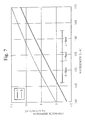
- Fig. 7 shows chromatic dispersion characteristics of the optical fibers A, B shown in Figs. 6A, 6B. Both optical fibers A and B exhibit values of chromatic dispersion greater than 2 ps/nm/km in the S-band, C-band and L-band, indicating that the properties are suitable for use in WDM.
- optical fiber B shown in Fig. 4 exhibits chromatic dispersion in excess of 10 ps/nm/km at 1625 nm, while it can be kept at less than 7 ps/nm/km in the optical fiber as shown in Fig. 7 so that this optical fiber is advantageous from the viewpoint of cumulative dispersion.
- chromatic dispersion of optical fiber B at 1625 nm shown in Fig. 7 is about the same as that of optical fiber A shown in Fig. 4, it enables to obtain a value of chromatic dispersion at 1460 nm greater than that of A shown in Fig 4, so that it is effective in reducing the effects of four-wave mixing in the S-band.
- the single-mode optical fiber in this example comprised by a core and a cladding, and whose core is comprised by not less than two layers having individual refractive indexes, can be derived by fabricating an optical fiber so that, when the core radius is changed, the fiber exhibits limiting values in more than one optical property (for example, the effective core area A eff and the dispersion slope exhibit limiting values) within a specific range of a reference radius, thereby enabling to realize a single-mode optical fiber, using an optical fiber having a single refractive index profile, that enables to vary the chromatic dispersion within a desired range and having desired chromatic dispersion characteristics, while maintaining substantially the same optical properties in the two fiber segments.
- the optical fiber having a single refractive index profile that enables to vary the chromatic dispersion within a desired range and having desired chromatic dispersion characteristics, while maintaining substantially the same optical properties in the two fiber segments.
- the dispersion slope can be held to less than 0.03 ps/nm 2 /km to enable to provide a single-mode optical fiber suitable for high speed transmission systems.
- the method enables to provide a single-mode optical fiber having reduced non-linear effects.
- the single-mode optical fiber in this example is fabricated so that more than one optical properties exhibit a limiting value of chromatic dispersion in a positive region and in a negative region.
- Fig. 1 shows the refractive index profile in the single-mode optical fiber used in this example.
- Figs. 8A to 8D show the variations in the optical properties upon changes in a core radius in an optical fiber having the refractive index profile shown in Fig. 1 and Table 5, and Fig. 8A shows the variation in the chromatic dispersion at 1550 nm wavelength; Fig. 8B shows the variation in the dispersion slope at 1550 nm wavelength; Fig. 8C shows the variation in the effective core area A eff at 1550 nm; and Fig. 8D shows the variation in the bending loss at a bending diameter of 20 ⁇ .
- the core radius shown in the x-axis is a relative value reference to design center of radius, and in this example, the reference core radius r 3 is set at 8.85 ⁇ m.
- Figs. 8A to 8D it is possible to vary the chromatic dispersion over a range of ⁇ 10 ps/nm/km by providing ⁇ 5 % change in the core radius with respect to the reference core that produces essentially zero chromatic dispersion.
- a eff and the dispersion slope exhibit limiting values in this region and become substantially constant.
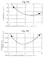
- Fig. 9A shows the variation in the effective core area A eff
- Fig. 9B shows the variation in the dispersion slope. In both cases, the horizontal axes represent chromatic dispersion at 1550 nm.
- solid points A, B refer to measured values of the optical fibers produced
- the solid lines refer to computed values.
- Figs. 9A, 9B show that the computed values agree substantially with the measured values.
- optical fiber A has a chromatic dispersion of -8 ps/nm/km, which is quite different from a chromatic dispersion of + 8 ps/nm/km for optical fiber B, it is possible to manufacture optical fibers having substantially the same A eff and the dispersion slope.
- the single-mode optical fiber in this example can be derived by fabricating an optical fiber so that, when the core radius is changed in the region in which the chromatic dispersion varies from a positive to a negative value, the fiber exhibits limiting values in more than one optical property (for example, the effective core area A eff and the dispersion slope), thereby enabling to realize a single-mode optical fiber, using an optical fiber having a single distribution of refractive indexes, that exhibits positive and negative chromatic dispersion while maintaining the optical properties substantially constant in the two fiber segments,.
- the optical property for example, the effective core area A eff and the dispersion slope
- the dispersion slope can be held to less than 0.03 ps/nm 2 /km to enable to provide a single-mode optical fiber suitable for high speed transmission system.
- the single-mode optical fiber in this example is based on an improvement in the dispersion characteristics described in the third example.
- the single-mode optical fiber in the third example produced an inversion in the sign of the chromatic dispersion while maintaining the A eff and the dispersion slope substantially constant, but in this example, the optical fiber produces an inversion in both dispersion values and the dispersion slope while maintaining the A eff unchanged.
- Fig. 1 shows the refractive index profile in the single-mode optical fiber used in this example.
- Figs. 11A to 11D show the variations in the optical properties upon changes in a core radius in an optical fiber having the refractive index profile shown in Fig. 1 and Table 7, and Fig. 11A shows the variation in the chromatic dispersion at 1550 nm wavelength; Fig. 11B shows the variation in the dispersion slope at 1550 nm wavelength; Fig. 11C shows the variation in the effective core area A eff at 1550 nm; and Fig. 11D shows the variation in the bending loss at a bending diameter of 20 ⁇ .
- the core radius shown in the x-axis is a relative value reference to design center of radius, and in this example, the reference core radius r 3 is set at 8.3 ⁇ m.
- the A eff exhibits limiting values when the core radius is changed, but the feature characteristic is the variation in the dispersion slope that is in contrast to the variation in the optical fiber in the first to third examples, in which the dispersion slope exhibited limiting values but the change itself occurred over a small region.
- this example differs from the foregoing examples in that the change in the dispersion slope occurs over a very large region, as shown in Fig. 11B, such that the values are inverted from a negative sign to a positive sign.
- Fig. 12A shows the variation in the effective core area A eff
- Fig. 12B shows the variation in the dispersion slope. In both cases, the horizontal axes represent chromatic dispersion at 1550 nm.
- solid points A, B refer to measured values of the optical fibers produced
- the solid lines refer to computed values.
- Figs 12A and 12B show that the computed values agree substantially with the measured values.
- Fig. 12C shows RDS (relative dispersion slope) values with respect to the chromatic dispersion, where RDS refers to a parameter defined by the following expression:
- RDS dispersion slope/chromatic dispersion in units of nm -1 .
- Optical fiber A and optical fiber B shown in Fig. 12C have essentially the same RDS values but the signs of the chromatic dispersion are opposite and their absolute values are equal in magnitude. It follows that the dispersion slope can be compensated by using a combination of such optical fibers.
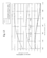
- Fig. 13 shows the chromatic dispersion of optical fibers A, B shown in Figs. 12A to 12C, and the chromatic dispersion of a composite optical line produced by joining optical fiber A to optical fiber B.
- This composite optical line has a segment length ratio of 1:1 for the two types of optical fibers.
- the composite optical line enables to control the absolute values of the chromatic dispersion to less than 2 ps/nm/km in all regions of the S-, C- and L-bands.
- the use of an optical fiber having the refractive index profile illustrated in this example enables to manufacture a self-compensating optical fiber that can correct its own dispersion characteristics by simply changing the core radius.
- the single-mode optical fiber of this example can be derived by fabricating an optical fiber so that, when the core radius is changed in a region where the dispersion slope varies from a positive value to a negative value, the fiber exhibits limiting values in more than one optical property (for example, the effective core area A eff and the dispersion slope) within a specific range of a reference radius in a region where the dispersion slope varies from a positive value to a negative value, so that the chromatic dispersion and the dispersion slope will exhibit opposite signs while maintaining the optical properties substantially constant in the two fiber segments.
- the optical property for example, the effective core area A eff and the dispersion slope
- a self-compensating optical line that corrects the dispersion slope is enabled by combining such single-mode fibers to produce a composite optical line.
Landscapes
- Chemical & Material Sciences (AREA)
- Dispersion Chemistry (AREA)
- Physics & Mathematics (AREA)
- General Physics & Mathematics (AREA)
- Optics & Photonics (AREA)
- Optical Communication System (AREA)
- Optical Fibers, Optical Fiber Cores, And Optical Fiber Bundles (AREA)
- Glass Compositions (AREA)
Abstract
Description
| r2/r1 | r3/r1 | Δ1 | Δ2 | Δ3 |
| 2.0 | 2.7 | 0.53 | -0.10 | 0.20 |
| Cut-off wavelength [nm] | Aeff [µm2] | MFD [µm] | Chromatic dispersion [ps/nm/km] | Dispersion slope [ps/nm2/km] | Bending loss [dB/m] |
| 1180 | 50.23 | 8.09 | +7.6 | +0.046 | 0.4 |
| Notes: values are estimated at 1550 nm wavelength; bending loss at 20 |
| r2/r1 | r3/r1 | Δ1 | Δ2 | Δ3 |
| 2.0 | 3.0 | 0.50 | -0.20 | 0.20 |
| Cut-off wavelength [nm] | Aeff [µm2] | MFD [µm] | Chromatic dispersion [ps/nm/km] | Dispersion slope [ps/nm2/km] | Bending loss [dB/m] |
| 1420 | 49.33 | 7.93 | +6.8 | +0.029 | 3.2 |
| Notes: values are estimated at 1550 nm wavelength; bending loss at 20 |
| r2/r1 | r3/r1 | Δ1 | Δ2 | Δ3 |
| 2.0 | 3.0 | 0.65 | -0.25 | 0.25 |
| Cut-off wavelength [nm] | Aeff [µm2] | MFD [µm] | Chromatic dispersion [ps/nm/km] | Dispersion slope [ps/nm2/km] | Bending loss [dB/m] |
| 1450 | 37.96 | 6.97 | +1.68 | +0.019 | 0.1 |
| Notes: values are estimated at 1550 nm wavelength; bending loss at 20 |
| r2/r1 | r3/r1 | Δ1 | Δ2 | Δ3 |
| 2.5 | 3.0 | 0.70 | -0.30 | 0.60 |
| Cut-off wavelength [nm] | Aeff [µm2] | MFD [µm] | Chromatic dispersion [ps/nm/km] | Dispersion slope [ps/nm2/km] | Bending loss [dB/m] |
| 1440 | 32.23 | 6.41 | +1.54 | +0.001 | 0.17 |
| Notes: values are estimated at 1550 nm wavelength; bending loss at 20 |
Claims (12)
- A single-mode optical fiber comprising a core and a cladding, wherein the core comprises two or more core layers having individual refractive indexes and at least one optical property exhibits an extreme value within a specific range of the core radius when a core radius is changed.
- A single-mode optical fiber according to claim 1, wherein the optical property exhibits the extreme value within a range of ±10 % of a reference radius of the core.
- A single-mode optical fiber according to claim 2, wherein the optical property exhibits the extreme value within a range of ±5 % of a reference radius of the core.
- A single-mode optical fiber according to claim 1, wherein at least one optical properties comprises chromatic dispersion dependency which exhibits the extreme value.
- A single-mode optical fiber according to claim 4, wherein an optical property exhibits the extreme value in a region extending from a positive chromatic dispersion to a negative chromatic dispersion.
- A single-mode optical fiber according to claim 1, wherein the optical property is a dispersion slope.
- A single-mode optical fiber according to claim 5, wherein the optical property exhibits the extreme value in a region extending from a positive dispersion slope to a negative dispersion slope.
- A single-mode optical fiber according to claim 1, wherein the optical property is an effective core area or a mode field diameter.
- A single-mode optical fiber according to claim 1, wherein the dispersion slope is 0.05 ps/nm2/km or less in an operating wavelength bandwidth.
- A single-mode optical fiber according to claim 1, wherein the dispersion slope is 0.03 ps/nm2/km or less in an operating wavelength bandwidth.
- A single-mode optical fiber according to claim 1, wherein at least one layer of the layers composing the core having individual refractive indexes has a refractive index which is less than a refractive index of a cladding.
- A composite optical line compensating the dispersion slope by combining the single-mode optical fiber according to claim 7.
Applications Claiming Priority (2)
| Application Number | Priority Date | Filing Date | Title |
|---|---|---|---|
| JP2001331283 | 2001-10-29 | ||
| JP2001331283A JP3886771B2 (en) | 2001-10-29 | 2001-10-29 | Single mode optical fiber and composite optical line for WDM |
Publications (3)
| Publication Number | Publication Date |
|---|---|
| EP1308755A2 true EP1308755A2 (en) | 2003-05-07 |
| EP1308755A3 EP1308755A3 (en) | 2004-08-04 |
| EP1308755B1 EP1308755B1 (en) | 2008-01-30 |
Family
ID=19146886
Family Applications (1)
| Application Number | Title | Priority Date | Filing Date |
|---|---|---|---|
| EP02292581A Expired - Lifetime EP1308755B1 (en) | 2001-10-29 | 2002-10-18 | Single-mode optical fiber and composite optical line |
Country Status (7)
| Country | Link |
|---|---|
| US (1) | US6895140B2 (en) |
| EP (1) | EP1308755B1 (en) |
| JP (1) | JP3886771B2 (en) |
| CN (1) | CN1415983A (en) |
| DE (1) | DE60224865T2 (en) |
| DK (1) | DK1308755T3 (en) |
| RU (1) | RU2248021C2 (en) |
Cited By (4)
| Publication number | Priority date | Publication date | Assignee | Title |
|---|---|---|---|---|
| US7050687B2 (en) | 2002-02-15 | 2006-05-23 | Corning Incorporated | Low slope dispersion shifted optical fiber |
| US7181118B2 (en) | 2002-07-31 | 2007-02-20 | Corning Incorporated | Non-zero dispersion shifted optical fiber having large effective area, low slope and low zero dispersion |
| WO2007125540A1 (en) * | 2006-05-02 | 2007-11-08 | Sterlite Optical Technologies Ltd. | Dispersion optimized optical fiber for wideband optical transmission |
| CN116449481A (en) * | 2023-03-29 | 2023-07-18 | 中国科学院上海光学精密机械研究所 | Rare earth doped large mode field phosphate optical fiber |
Families Citing this family (6)
| Publication number | Priority date | Publication date | Assignee | Title |
|---|---|---|---|---|
| US7103251B2 (en) * | 2002-12-31 | 2006-09-05 | Corning Incorporated | Dispersion flattened NZDSF fiber |
| US7209620B2 (en) * | 2003-01-23 | 2007-04-24 | Sterlite Optical Technologies Limited | Dispersion optimized fiber having higher spot area |
| US7272289B2 (en) * | 2005-09-30 | 2007-09-18 | Corning Incorporated | Low bend loss optical fiber |
| US9366810B2 (en) * | 2012-08-29 | 2016-06-14 | Ofs Fitel, Llc | Double-clad, gain-producing fibers with increased cladding absoroption while maintaining single-mode operation |
| US9366806B2 (en) * | 2012-08-29 | 2016-06-14 | Ofs Fitel, Llc | Gain-producing fibers with increased cladding absorption while maintaining single-mode operation |
| CN107450124B (en) * | 2016-05-30 | 2020-10-09 | 天津大学 | A kind of broadband dispersion control fiber and its dispersion control method |
Family Cites Families (18)
| Publication number | Priority date | Publication date | Assignee | Title |
|---|---|---|---|---|
| US4372647A (en) | 1979-10-08 | 1983-02-08 | Nippon Telegraph & Telephone Public Corporation | Single mode optical fibers |
| JPH07261048A (en) * | 1994-03-23 | 1995-10-13 | Sumitomo Electric Ind Ltd | Dispersion compensating fiber |
| JPH08220362A (en) | 1995-02-10 | 1996-08-30 | Fujikura Ltd | Dispersion-shifted optical fiber |
| AU693329B2 (en) * | 1995-04-13 | 1998-06-25 | Corning Incorporated | Dispersion managed optical waveguide |
| US5894537A (en) * | 1996-01-11 | 1999-04-13 | Corning Incorporated | Dispersion managed optical waveguide |
| US5613028A (en) * | 1995-08-10 | 1997-03-18 | Corning Incorporated | Control of dispersion in an optical waveguide |
| JPH09288220A (en) | 1996-02-20 | 1997-11-04 | Kokusai Denshin Denwa Co Ltd <Kdd> | Optical fiber |
| CA2229280A1 (en) | 1997-02-12 | 1998-08-12 | Sumitomo Electric Industries, Ltd. | Dispersion-shifted fiber |
| US5887105A (en) * | 1997-04-28 | 1999-03-23 | Corning Incorporated | Dispersion managed optical fiber |
| US5878182A (en) | 1997-06-05 | 1999-03-02 | Lucent Technologies Inc. | Optical fiber having a low-dispersion slope in the erbium amplifier region |
| JP2001255433A (en) | 1997-12-05 | 2001-09-21 | Sumitomo Electric Ind Ltd | Dispersion flat optical fiber |
| US6169837B1 (en) * | 1997-12-05 | 2001-01-02 | Sumitomo Electric Industries, Ltd. | Dispersion-flattened optical fiber |
| JP4238479B2 (en) | 1997-12-22 | 2009-03-18 | 住友電気工業株式会社 | Optical transmission line |
| US6317549B1 (en) | 1999-05-24 | 2001-11-13 | Lucent Technologies Inc. | Optical fiber having negative dispersion and low slope in the Erbium amplifier region |
| US6466721B1 (en) | 1999-07-19 | 2002-10-15 | Sumitomo Electric Industries, Ltd. | Dispersion compensating optical fiber and optical transmission line |
| JP3471271B2 (en) | 1999-08-12 | 2003-12-02 | 株式会社フジクラ | Optical fiber and optical transmission system |
| RU2216755C2 (en) | 2000-02-25 | 2003-11-20 | Дзе Фурукава Электрик Ко., Лтд. | Low-dispersion optical fiber and optical transmission system with use of low-dispersion optical fiber |
| JP2002162529A (en) | 2000-11-28 | 2002-06-07 | Furukawa Electric Co Ltd:The | Optical fiber and optical communication system using the optical fiber |
-
2001
- 2001-10-29 JP JP2001331283A patent/JP3886771B2/en not_active Expired - Fee Related
-
2002
- 2002-10-16 US US10/270,577 patent/US6895140B2/en not_active Expired - Fee Related
- 2002-10-18 DK DK02292581T patent/DK1308755T3/en active
- 2002-10-18 EP EP02292581A patent/EP1308755B1/en not_active Expired - Lifetime
- 2002-10-18 DE DE60224865T patent/DE60224865T2/en not_active Expired - Lifetime
- 2002-10-25 RU RU2002128756/28A patent/RU2248021C2/en not_active IP Right Cessation
- 2002-10-25 CN CN02147049.9A patent/CN1415983A/en active Pending
Cited By (4)
| Publication number | Priority date | Publication date | Assignee | Title |
|---|---|---|---|---|
| US7050687B2 (en) | 2002-02-15 | 2006-05-23 | Corning Incorporated | Low slope dispersion shifted optical fiber |
| US7181118B2 (en) | 2002-07-31 | 2007-02-20 | Corning Incorporated | Non-zero dispersion shifted optical fiber having large effective area, low slope and low zero dispersion |
| WO2007125540A1 (en) * | 2006-05-02 | 2007-11-08 | Sterlite Optical Technologies Ltd. | Dispersion optimized optical fiber for wideband optical transmission |
| CN116449481A (en) * | 2023-03-29 | 2023-07-18 | 中国科学院上海光学精密机械研究所 | Rare earth doped large mode field phosphate optical fiber |
Also Published As
| Publication number | Publication date |
|---|---|
| JP2003131059A (en) | 2003-05-08 |
| RU2248021C2 (en) | 2005-03-10 |
| DE60224865T2 (en) | 2009-01-22 |
| US6895140B2 (en) | 2005-05-17 |
| DE60224865D1 (en) | 2008-03-20 |
| EP1308755A3 (en) | 2004-08-04 |
| JP3886771B2 (en) | 2007-02-28 |
| CN1415983A (en) | 2003-05-07 |
| DK1308755T3 (en) | 2008-06-09 |
| EP1308755B1 (en) | 2008-01-30 |
| US20030169988A1 (en) | 2003-09-11 |
Similar Documents
| Publication | Publication Date | Title |
|---|---|---|
| CA2277332C (en) | Dispersion-flattened optical fiber | |
| US20040228593A1 (en) | Super-large-effective-area (SLA) optical fiber and communication system incorporating the same | |
| KR20010101071A (en) | Optical fiber and optical transmission system including the same | |
| EP1130426B1 (en) | Dispersion shifted optical fiber | |
| CN1520527A (en) | Dispersion Compensating Fiber | |
| US20040062500A1 (en) | Low-dispersion optical fiber and optical transmission system using the low-dispersion optical fiber | |
| JP2002522812A (en) | Dispersion shifted single mode optical fiber with outer ring | |
| US6895140B2 (en) | Single-mode optical fiber and composite optical line | |
| US6813430B2 (en) | Dispersion-compensating optical fiber and hybrid transmission line | |
| EP1486805B1 (en) | Large-effective-area inverse dispersion compensating fiber | |
| US7095932B2 (en) | Chromatic dispersion compensating optical fiber | |
| JP2003232950A (en) | Optical fiber | |
| KR20030007516A (en) | Dispersion-compensating optical fiber with W-shaped index profile | |
| US7171092B2 (en) | Optical fiber with chromatic dispersion compensation in the S band | |
| EP0989420A1 (en) | Wavelength-multiplexing optical transmission channel and optical fiber used therefor | |
| CN100389333C (en) | Dispersion compensation optical fiber | |
| CN100397118C (en) | Dispersion Compensating Fiber Using Higher Order Modes in S-Band | |
| JP2002071996A (en) | Dispersion compensating optical fiber and optical fiber composite transmission line | |
| JP2002182056A (en) | Dispersion compensating optical fiber, and optical transmission line and dispersion compensating module including the same | |
| KR19990030404A (en) | A dispersion-shifted optical fiber having a small dispersion slope | |
| JP2002098853A (en) | Dispersion compensating optical fiber and optical fiber transmission line using the same | |
| JP2002116338A (en) | Optical fiber and optical transmission line using the same | |
| JP2003294970A (en) | Dispersion compensating optical fiber and optical fiber composite transmission line | |
| JP2006514316A (en) | Chromatic dispersion compensating optical fiber | |
| JPH0460503A (en) | low dispersion optical fiber |
Legal Events
| Date | Code | Title | Description |
|---|---|---|---|
| PUAI | Public reference made under article 153(3) epc to a published international application that has entered the european phase |
Free format text: ORIGINAL CODE: 0009012 |
|
| 17P | Request for examination filed |
Effective date: 20021024 |
|
| AK | Designated contracting states |
Designated state(s): AT BE BG CH CY CZ DE DK EE ES FI FR GB GR IE IT LI LU MC NL PT SE SK TR |
|
| AX | Request for extension of the european patent |
Extension state: AL LT LV MK RO SI |
|
| RAP1 | Party data changed (applicant data changed or rights of an application transferred) |
Owner name: FUJIKURA LTD. |
|
| PUAL | Search report despatched |
Free format text: ORIGINAL CODE: 0009013 |
|
| AK | Designated contracting states |
Kind code of ref document: A3 Designated state(s): AT BE BG CH CY CZ DE DK EE ES FI FR GB GR IE IT LI LU MC NL PT SE SK TR |
|
| AX | Request for extension of the european patent |
Extension state: AL LT LV MK RO SI |
|
| RIC1 | Information provided on ipc code assigned before grant |
Ipc: 7G 02B 6/16 A Ipc: 7G 02B 6/22 B |
|
| 17Q | First examination report despatched |
Effective date: 20041115 |
|
| AKX | Designation fees paid |
Designated state(s): DE DK FR GB IT NL |
|
| RBV | Designated contracting states (corrected) |
Designated state(s): DE DK FR GB IT NL |
|
| 17Q | First examination report despatched |
Effective date: 20041115 |
|
| GRAP | Despatch of communication of intention to grant a patent |
Free format text: ORIGINAL CODE: EPIDOSNIGR1 |
|
| RIC1 | Information provided on ipc code assigned before grant |
Ipc: G02B 6/036 20060101ALI20070828BHEP Ipc: G02B 6/02 20060101AFI20070828BHEP |
|
| GRAS | Grant fee paid |
Free format text: ORIGINAL CODE: EPIDOSNIGR3 |
|
| GRAA | (expected) grant |
Free format text: ORIGINAL CODE: 0009210 |
|
| RIN1 | Information on inventor provided before grant (corrected) |
Inventor name: HIMENO, KUNIHARU Inventor name: MATSUO, SHOICHIRO Inventor name: HARADA, KOICHI |
|
| AK | Designated contracting states |
Kind code of ref document: B1 Designated state(s): DE DK FR GB IT NL |
|
| REG | Reference to a national code |
Ref country code: GB Ref legal event code: FG4D |
|
| REF | Corresponds to: |
Ref document number: 60224865 Country of ref document: DE Date of ref document: 20080320 Kind code of ref document: P |
|
| REG | Reference to a national code |
Ref country code: DK Ref legal event code: T3 |
|
| ET | Fr: translation filed | ||
| PLBE | No opposition filed within time limit |
Free format text: ORIGINAL CODE: 0009261 |
|
| STAA | Information on the status of an ep patent application or granted ep patent |
Free format text: STATUS: NO OPPOSITION FILED WITHIN TIME LIMIT |
|
| 26N | No opposition filed |
Effective date: 20081031 |
|
| PGFP | Annual fee paid to national office [announced via postgrant information from national office to epo] |
Ref country code: DE Payment date: 20101013 Year of fee payment: 9 |
|
| PGFP | Annual fee paid to national office [announced via postgrant information from national office to epo] |
Ref country code: GB Payment date: 20101013 Year of fee payment: 9 |
|
| GBPC | Gb: european patent ceased through non-payment of renewal fee |
Effective date: 20111018 |
|
| PG25 | Lapsed in a contracting state [announced via postgrant information from national office to epo] |
Ref country code: DE Free format text: LAPSE BECAUSE OF NON-PAYMENT OF DUE FEES Effective date: 20120501 |
|
| REG | Reference to a national code |
Ref country code: DE Ref legal event code: R119 Ref document number: 60224865 Country of ref document: DE Effective date: 20120501 |
|
| PG25 | Lapsed in a contracting state [announced via postgrant information from national office to epo] |
Ref country code: GB Free format text: LAPSE BECAUSE OF NON-PAYMENT OF DUE FEES Effective date: 20111018 |
|
| PGFP | Annual fee paid to national office [announced via postgrant information from national office to epo] |
Ref country code: NL Payment date: 20130910 Year of fee payment: 12 |
|
| PGFP | Annual fee paid to national office [announced via postgrant information from national office to epo] |
Ref country code: FR Payment date: 20131009 Year of fee payment: 12 |
|
| PGFP | Annual fee paid to national office [announced via postgrant information from national office to epo] |
Ref country code: IT Payment date: 20131018 Year of fee payment: 12 |
|
| REG | Reference to a national code |
Ref country code: NL Ref legal event code: V1 Effective date: 20150501 |
|
| REG | Reference to a national code |
Ref country code: FR Ref legal event code: ST Effective date: 20150630 |
|
| PG25 | Lapsed in a contracting state [announced via postgrant information from national office to epo] |
Ref country code: IT Free format text: LAPSE BECAUSE OF NON-PAYMENT OF DUE FEES Effective date: 20141018 Ref country code: NL Free format text: LAPSE BECAUSE OF NON-PAYMENT OF DUE FEES Effective date: 20150501 Ref country code: FR Free format text: LAPSE BECAUSE OF NON-PAYMENT OF DUE FEES Effective date: 20141031 |
|
| PGFP | Annual fee paid to national office [announced via postgrant information from national office to epo] |
Ref country code: DK Payment date: 20151012 Year of fee payment: 14 |
|
| REG | Reference to a national code |
Ref country code: DK Ref legal event code: EBP Effective date: 20161031 |
|
| PG25 | Lapsed in a contracting state [announced via postgrant information from national office to epo] |
Ref country code: DK Free format text: LAPSE BECAUSE OF NON-PAYMENT OF DUE FEES Effective date: 20161031 |