EP1308614B1 - Système de motorisation pour véhicule - Google Patents
Système de motorisation pour véhicule Download PDFInfo
- Publication number
- EP1308614B1 EP1308614B1 EP02292716A EP02292716A EP1308614B1 EP 1308614 B1 EP1308614 B1 EP 1308614B1 EP 02292716 A EP02292716 A EP 02292716A EP 02292716 A EP02292716 A EP 02292716A EP 1308614 B1 EP1308614 B1 EP 1308614B1
- Authority
- EP
- European Patent Office
- Prior art keywords
- engine
- gas
- valve
- accumulation
- inlet
- Prior art date
- Legal status (The legal status is an assumption and is not a legal conclusion. Google has not performed a legal analysis and makes no representation as to the accuracy of the status listed.)
- Expired - Lifetime
Links
- 238000009825 accumulation Methods 0.000 claims description 40
- 238000002485 combustion reaction Methods 0.000 claims description 4
- 239000000446 fuel Substances 0.000 claims description 4
- 238000007599 discharging Methods 0.000 claims 2
- 239000007789 gas Substances 0.000 description 29
- 235000021183 entrée Nutrition 0.000 description 3
- 238000010586 diagram Methods 0.000 description 1
- 230000004048 modification Effects 0.000 description 1
- 238000012986 modification Methods 0.000 description 1
- 230000035484 reaction time Effects 0.000 description 1
Images
Classifications
-
- F—MECHANICAL ENGINEERING; LIGHTING; HEATING; WEAPONS; BLASTING
- F02—COMBUSTION ENGINES; HOT-GAS OR COMBUSTION-PRODUCT ENGINE PLANTS
- F02D—CONTROLLING COMBUSTION ENGINES
- F02D17/00—Controlling engines by cutting out individual cylinders; Rendering engines inoperative or idling
- F02D17/02—Cutting-out
- F02D17/023—Cutting-out the inactive cylinders acting as compressor other than for pumping air into the exhaust system
-
- F—MECHANICAL ENGINEERING; LIGHTING; HEATING; WEAPONS; BLASTING
- F02—COMBUSTION ENGINES; HOT-GAS OR COMBUSTION-PRODUCT ENGINE PLANTS
- F02B—INTERNAL-COMBUSTION PISTON ENGINES; COMBUSTION ENGINES IN GENERAL
- F02B37/00—Engines characterised by provision of pumps driven at least for part of the time by exhaust
- F02B37/04—Engines with exhaust drive and other drive of pumps, e.g. with exhaust-driven pump and mechanically-driven second pump
- F02B37/10—Engines with exhaust drive and other drive of pumps, e.g. with exhaust-driven pump and mechanically-driven second pump at least one pump being alternatively or simultaneously driven by exhaust and other drive, e.g. by pressurised fluid from a reservoir or an engine-driven pump
-
- F—MECHANICAL ENGINEERING; LIGHTING; HEATING; WEAPONS; BLASTING
- F02—COMBUSTION ENGINES; HOT-GAS OR COMBUSTION-PRODUCT ENGINE PLANTS
- F02M—SUPPLYING COMBUSTION ENGINES IN GENERAL WITH COMBUSTIBLE MIXTURES OR CONSTITUENTS THEREOF
- F02M26/00—Engine-pertinent apparatus for adding exhaust gases to combustion-air, main fuel or fuel-air mixture, e.g. by exhaust gas recirculation [EGR] systems
- F02M26/13—Arrangement or layout of EGR passages, e.g. in relation to specific engine parts or for incorporation of accessories
- F02M26/14—Arrangement or layout of EGR passages, e.g. in relation to specific engine parts or for incorporation of accessories in relation to the exhaust system
- F02M26/16—Arrangement or layout of EGR passages, e.g. in relation to specific engine parts or for incorporation of accessories in relation to the exhaust system with EGR valves located at or near the connection to the exhaust system
-
- F—MECHANICAL ENGINEERING; LIGHTING; HEATING; WEAPONS; BLASTING
- F02—COMBUSTION ENGINES; HOT-GAS OR COMBUSTION-PRODUCT ENGINE PLANTS
- F02M—SUPPLYING COMBUSTION ENGINES IN GENERAL WITH COMBUSTIBLE MIXTURES OR CONSTITUENTS THEREOF
- F02M26/00—Engine-pertinent apparatus for adding exhaust gases to combustion-air, main fuel or fuel-air mixture, e.g. by exhaust gas recirculation [EGR] systems
- F02M26/13—Arrangement or layout of EGR passages, e.g. in relation to specific engine parts or for incorporation of accessories
- F02M26/37—Arrangement or layout of EGR passages, e.g. in relation to specific engine parts or for incorporation of accessories with temporary storage of recirculated exhaust gas
-
- F—MECHANICAL ENGINEERING; LIGHTING; HEATING; WEAPONS; BLASTING
- F02—COMBUSTION ENGINES; HOT-GAS OR COMBUSTION-PRODUCT ENGINE PLANTS
- F02M—SUPPLYING COMBUSTION ENGINES IN GENERAL WITH COMBUSTIBLE MIXTURES OR CONSTITUENTS THEREOF
- F02M26/00—Engine-pertinent apparatus for adding exhaust gases to combustion-air, main fuel or fuel-air mixture, e.g. by exhaust gas recirculation [EGR] systems
- F02M26/13—Arrangement or layout of EGR passages, e.g. in relation to specific engine parts or for incorporation of accessories
- F02M26/40—Arrangement or layout of EGR passages, e.g. in relation to specific engine parts or for incorporation of accessories with timing means in the recirculation passage, e.g. cyclically operating valves or regenerators; with arrangements involving pressure pulsations
-
- F—MECHANICAL ENGINEERING; LIGHTING; HEATING; WEAPONS; BLASTING
- F02—COMBUSTION ENGINES; HOT-GAS OR COMBUSTION-PRODUCT ENGINE PLANTS
- F02M—SUPPLYING COMBUSTION ENGINES IN GENERAL WITH COMBUSTIBLE MIXTURES OR CONSTITUENTS THEREOF
- F02M26/00—Engine-pertinent apparatus for adding exhaust gases to combustion-air, main fuel or fuel-air mixture, e.g. by exhaust gas recirculation [EGR] systems
- F02M26/51—EGR valves combined with other devices, e.g. with intake valves or compressors
-
- F—MECHANICAL ENGINEERING; LIGHTING; HEATING; WEAPONS; BLASTING
- F02—COMBUSTION ENGINES; HOT-GAS OR COMBUSTION-PRODUCT ENGINE PLANTS
- F02M—SUPPLYING COMBUSTION ENGINES IN GENERAL WITH COMBUSTIBLE MIXTURES OR CONSTITUENTS THEREOF
- F02M26/00—Engine-pertinent apparatus for adding exhaust gases to combustion-air, main fuel or fuel-air mixture, e.g. by exhaust gas recirculation [EGR] systems
- F02M26/02—EGR systems specially adapted for supercharged engines
- F02M26/04—EGR systems specially adapted for supercharged engines with a single turbocharger
- F02M26/05—High pressure loops, i.e. wherein recirculated exhaust gas is taken out from the exhaust system upstream of the turbine and reintroduced into the intake system downstream of the compressor
-
- Y—GENERAL TAGGING OF NEW TECHNOLOGICAL DEVELOPMENTS; GENERAL TAGGING OF CROSS-SECTIONAL TECHNOLOGIES SPANNING OVER SEVERAL SECTIONS OF THE IPC; TECHNICAL SUBJECTS COVERED BY FORMER USPC CROSS-REFERENCE ART COLLECTIONS [XRACs] AND DIGESTS
- Y02—TECHNOLOGIES OR APPLICATIONS FOR MITIGATION OR ADAPTATION AGAINST CLIMATE CHANGE
- Y02T—CLIMATE CHANGE MITIGATION TECHNOLOGIES RELATED TO TRANSPORTATION
- Y02T10/00—Road transport of goods or passengers
- Y02T10/10—Internal combustion engine [ICE] based vehicles
- Y02T10/12—Improving ICE efficiencies
Definitions
- the latter then comprises means for accumulating pressurized gas, in the form of a gas reservoir, associated with means for controlling their charge / discharge, in the form of a valve provided for in FIG. the cylinder head of the engine, at a corresponding cylinder thereof, this valve being controlled to implement a charging phase of these accumulation means and a discharge phase thereof from and in the cylinder.
- the object of the invention is therefore to solve these problems.
- the subject of the invention is a drive system for a motor vehicle, of the type comprising an internal combustion engine provided with input gas inlet means and exhaust gas outlet means, and means of accumulation of pressurized gas associated with charge / discharge control means adapted to implement a charging phase thereof, during which the supply of fuel to at least some of the engine cylinders is cut off to operating the or each cylinder whose supply is cut off, in compressor, and a discharge phase thereof, during which the gas is used to improve the performance of the engine, characterized in that the accumulation means pressurized gas comprises a gas outlet connected through valve means controllable by the control means, to a turbocharger associated with the engine, for injecting gas therein.
- This engine is provided with input gas inlet means, which are designated by the general reference 2 and outlet gas exhaust means, designated by the general reference 3.
- pressurized gas accumulation means which are for example in the form of a tank, designated by the general reference 4 and associated with their charge / discharge control means, designated by the general reference 5 and comprising for example any appropriate computer, adapted to implement a charging phase thereof and a discharge phase thereof in a conventional manner.
- the supply of fuel to at least some of the cylinders of the engine is cut off, in order to operate this or each cylinder whose supply is cut off, in compressor, thus ensuring the load of these accumulation means.
- the gas is used to improve the performance of the engine.
- the pressurized gas accumulation means 4 comprise a gas inlet designated by the general reference 6 connected to the exhaust means 3 of the heat engine 1.
- these exhaust means may comprise, at the output of the heat engine 1, means forming a piloting valve with two outputs, designated by the general reference 7 on this figure 1 , one of which is connected to the rest of these exhaust means 3 and the other of which is connected to the inlet 6 of the accumulation means 4.
- valve means then have an inlet designated by the general reference 8 connected to the output of the motor and two outputs respectively 9 and 10, one of which 9 is connected to the rest of the exhaust means 3, and the other 10, is connected to the input 6 of the accumulation means 4.
- the position of this shutter is controlled conventionally by the control means 5.
- the engine is associated with a turbocharger designated by the general reference 15 and comprising a compressor portion 16 and a turbine portion 17.
- the compressor portion 16 is associated with the gas intake means 2 in the engine, while the turbine portion 17 is associated with the exhaust means 3 thereof.
- the means 7 forming a controllable valve with two outputs then comprise an output associated with this turbine portion 17 of the turbocharger 15 and another output connected to the inlet of the pressurized gas accumulation means 4.
- the accumulation means can be connected to the turbine portion and / or to the compressor portion of this turbocharger, as shown in solid lines and in dashed lines respectively on this figure 1 .
Landscapes
- Engineering & Computer Science (AREA)
- Chemical & Material Sciences (AREA)
- Combustion & Propulsion (AREA)
- Mechanical Engineering (AREA)
- General Engineering & Computer Science (AREA)
- Supercharger (AREA)
- Control Of Multiple Motors (AREA)
- Control Of Motors That Do Not Use Commutators (AREA)
- Control Of Electric Motors In General (AREA)
- Auxiliary Drives, Propulsion Controls, And Safety Devices (AREA)
Description
- La présente invention concerne un système de motorisation pour véhicule automobile.
- Plus particulièrement, l'invention se rapporte à un système de motorisation qui comporte un moteur à combustion interne muni de moyens d'admission de gaz en entrée et de moyens d'échappement de gaz en sortie et des moyens de stockage de gaz sous pression associés à des moyens de commande de leur charge/décharge adaptés pour mettre en oeuvre une phase de charge de ceux-ci, pendant laquelle l'alimentation en carburant d'au moins certains cylindres du moteur est coupée pour faire fonctionner le ou chaque cylindre dont l'alimentation est coupée, en compresseur, et une phase de décharge de ceux-ci, au cours de laquelle le gaz est utilisé pour améliorer les performances du moteur.
- De tels systèmes sont déjà décrits par exemple dans les documents
US-A-3 963 379 etWO 00/65210 A - On trouvera un autre exemple d'un tel système de motorisation dans le document SAE TECHNICAL PAPER SERIES, 1999-01-0623, intitulé « New Cycles for Automobile Engines » de Michael M. SCHECHTER, International Congress and Exposition, Detroit, Michigan, March 1-4, 1999.
- L'idée générale à la base du développement de tels systèmes, consiste à récupérer de l'énergie lors de certaines phases de fonctionnement du moteur, sous la forme de gaz comprimé dans les moyens d'accumulation et de réutiliser cette énergie dans d'autres phases de fonctionnement de celui-ci.
- En particulier, de l'énergie peut être récupérée en phase de décélération et de freinage du véhicule.
- Sur la
figure 2 du document de Michael M. SCHECHTER mentionné précédemment, on a représenté un exemple de réalisation d'un tel système. - Celui-ci comporte alors des moyens d'accumulation de gaz sous pression, se présentant sous la forme d'un réservoir de gaz, associés à des moyens de commande de leur charge/décharge, se présentant sous la forme d'une soupape prévue dans la culasse du moteur, au niveau d'un cylindre correspondant de celui-ci, cette soupape étant commandée pour mettre en oeuvre une phase de charge de ces moyens d'accumulation et une phase de décharge de ceux-ci à partir du et dans le cylindre.
- On conçoit cependant qu'une telle structure présente un certain nombre d'inconvénients, car la soupape correspondante nécessite une modification très importante de la culasse du moteur et des moyens de commande relativement complexes.
- Le but de l'invention est donc de résoudre ces problèmes.
- A cet effet, l'invention a pour objet un système de motorisation pour véhicule automobile, du type comportant un moteur à combustion interne muni de moyens d'admission de gaz en entrée et de moyens d'échappement de gaz en sortie, et des moyens d'accumulation de gaz sous pression associés à des moyens de commande de leur charge/décharge adaptés pour mettre en oeuvre une phase de charge de ceux-ci, pendant laquelle l'alimentation en carburant d'au moins certains cylindres du moteur est coupée pour faire fonctionner le ou chaque cylindre dont l'alimentation est coupée, en compresseur, et une phase de décharge de ceux-ci, au cours de laquelle le gaz est utilisé pour améliorer les performances du moteur, caractérisé en ce que les moyens d'accumulation de gaz sous pression comportent une sortie de gaz raccordée à travers des moyens formant vanne pilotable par les moyens de commande, à un turbocompresseur associé au moteur, pour injecter du gaz dans celui-ci.
- Selon d'autres caractéristiques :
- les moyens d'accumulation de gaz sous pression comportent une entrée de gaz raccordée aux moyens d'échappement du moteur thermique ;
- les moyens d'échappement comprennent en sortie du moteur, des moyens formant vanne pilotable à deux voies, dont l'une est raccordée au reste de ces moyens d'échappement et dont l'autre est raccordée à l'entrée des moyens d'accumulation et en ce que les moyens de commande sont adaptés, lors de la phase de charge des moyens d'accumulation, pour commander les moyens formant vanne afin de raccorder la sortie du moteur à ces moyens d'accumulation ;
- un clapet d'anti-retour est interposé entre les moyens formant vanne et l'entrée des moyens d'accumulation ;
- les moyens formant clapet d'anti-retour sont intégrés dans les moyens formant vanne pilotable au niveau de sa sortie raccordée aux moyens d'accumulation.
- L'invention sera mieux comprise à la lecture de la description qui va suivre, donnée uniquement à titre d'exemple et faite en se référant aux dessins annexés, sur lesquels :
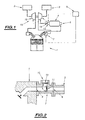
- la
Fig.1 représente un schéma synoptique illustrant la structure générale d'une forme de réalisation d'un système de motorisation selon l'invention ; et - la
Fig.2 représente une vue en coupe schématique de moyens formant vanne pilotable à deux sorties, entrant dans la constitution d'un tel système. - On a en effet représenté sur la
figure 1 , un système de motorisation pour véhicule automobile, du type comportant un moteur à combustion interne qui est désigné par la référence générale 1 sur cette figure et qui est par exemple schématisé par un cylindre de celui-ci. - Ce moteur est muni de moyens d'admission de gaz en entrée, qui sont désignés par la référence générale 2 et de moyens d'échappement de gaz en sortie, désignés par la référence générale 3.
- De plus, il est prévu des moyens d'accumulation de gaz sous pression qui se présentent par exemple sous la forme d'un réservoir, désignés par la référence générale 4 et associés à des moyens de commande de leur charge/décharge, désignés par la référence générale 5 et comportant par exemple tout calculateur approprié, adapté pour mettre en oeuvre une phase de charge de ceux-ci et une phase de décharge de ceux-ci de façon classique.
- Pendant la phase de charge des moyens d'accumulation de gaz sous pression 4, l'alimentation en carburant d'au moins certains des cylindres du moteur est coupée, pour faire fonctionner ce ou chaque cylindre dont l'alimentation est coupée, en compresseur, permettant ainsi d'assurer la charge de ces moyens d'accumulation.
- Durant la phase de décharge de ces moyens d'accumulation, le gaz est utilisé pour améliorer les performances du moteur.
- Comme cela est illustré sur cette
figure 1 , les moyens d'accumulation de gaz sous pression 4 comportent une entrée de gaz désignée par la référence générale 6 raccordée aux moyens d'échappement 3 du moteur thermique 1. - En fait, ces moyens d'échappement peuvent comporter en sortie du moteur thermique 1, des moyens formant vanne pilotable à deux sorties, désignés par la référence générale 7 sur cette
figure 1 , dont l'une est raccordée au reste de ces moyens d'échappement 3 et dont l'autre, est raccordée à l'entrée 6 des moyens d'accumulation 4. - Les moyens de commande 5 sont alors adaptés, lors de la phase de charge des moyens d'accumulation, pour commander les moyens formant vanne 7, afin de raccorder la sortie du moteur 1 à ces moyens d'accumulation 4.
- On a représenté sur la
figure 2 , un exemple de réalisation de tels moyens formant vanne pilotable à deux sorties. - Comme cela est représenté, ces moyens 7 sont interposés entre la sortie d'échappement correspondante du moteur 1 et le reste des moyens d'échappement 3 de celui-ci.
- Ces moyens formant vanne présentent alors une entrée désignée par la référence générale 8 raccordée à la sortie du moteur et deux sorties respectivement 9 et 10, dont l'une 9, est raccordée au reste des moyens d'échappement 3, et dont l'autre 10, est raccordée à l'entrée 6 des moyens d'accumulation 4.
- Un obturateur déplaçable désigné par la référence générale 11, est alors prévu dans ces moyens formant vanne, pour diriger les gaz en sortie du moteur, soit vers le reste des moyens d'échappement 3, soit vers l'entrée des moyens d'accumulation 4.
- La position de cet obturateur est pilotée de façon classique par les moyens de commande 5.
- Un clapet d'anti-retour est interposé entre les moyens formant vanne et l'entrée des moyens d'accumulation.
- Ce clapet est désigné par la référence générale 12 sur cette
figure 2 et est de préférence intégré dans ces moyens formant vanne pilotable au niveau de la sortie 10 raccordée aux moyens d'accumulation. - Comme cela est représenté sur la
figure 1 , le moteur est associé à un turbocompresseur désigné par la référence générale 15 et comportant une portion de compresseur 16 et une portion de turbine 17. - De façon classique, la portion de compresseur 16 est associée aux moyens d'admission des gaz 2 dans le moteur, tandis que la portion de turbine 17 est associée aux moyens d'échappement 3 de celui-ci.
- Les moyens 7 formant vanne pilotable à deux sorties comportent alors une sortie associée à cette portion de turbine 17 du turbocompresseur 15 et une autre sortie raccordée à l'entrée des moyens d'accumulation de gaz sous pression 4.
- La sortie des moyens d'accumulation 4, désignée par la référence générale 13, est raccordée à travers des moyens formant vanne pilotable 14 au turbocompresseur 15 associé à ce moteur.
- Ainsi les moyens d'accumulation peuvent être raccordés à la portion de turbine et/ou à la portion de compresseur de ce turbocompresseur, comme cela est illustré en trait plein et en pointillés respectivement sur cette
figure 1 . - Ceci permet d'injecter du gaz sous pression sur cette ou ces portions du turbocompresseur lorsqu'on le souhaite.
- L'utilisation du gaz sous pression injecté dans le turbocompresseur, permet d'en améliorer les performances et par conséquent, celles du moteur. On peut ainsi réduire voire éliminer le temps de réaction d'un turbocompresseur en raison de la montée en régime relativement lente de la turbine de celui-ci, sous l'action des gaz d'échappement seuls.
- Il va de soi bien entendu que d'autres modes de réalisation encore peuvent être envisagés.
Claims (5)
- Système de motorisation pour véhicule automobile, du type comportant un moteur à combustion interne (1) muni de moyens d'admission de gaz (2) en entrée et de moyens d'échappement de gaz (3) en sortie, et des moyens d'accumulation de gaz sous pression (4) associés à des moyens de commande (5) de leur charge/décharge adaptés pour mettre en oeuvre une phase de charge de ceux-ci, pendant laquelle l'alimentation en carburant d'au moins certains cylindres du moteur (1) est coupée pour faire fonctionner le ou chaque cylindre dont l'alimentation est coupée, en compresseur, et une phase de décharge de ceux-ci, au cours de laquelle le gaz est utilisé pour améliorer les performances du moteur, caractérisé en ce que les moyens d'accumulation de gaz sous pression (4) comportent une sortie de gaz (13) raccordée à travers des moyens formant vanne (14) pilotable par les moyens de commande (5), à un turbocompresseur (15) associé au moteur (1), pour injecter du gaz dans celui-ci.
- Système selon la revendication 1, caractérisé en ce que les moyens d'accumulation de gaz sous pression (4) comportent une entrée de gaz (6) raccordée aux moyens d'échappement (3) du moteur thermique (1).
- Système selon la revendication 2, caractérisé en ce que les moyens d'échappement comprennent en sortie du moteur, des moyens formant vanne pilotable (7) à deux voies (9,10), dont l'une (9) est raccordée au reste de ces moyens d'échappement (3) et dont l'autre (10) est raccordée à l'entrée (6) des moyens d'accumulation (4) et en ce que les moyens de commande (5) sont adaptés, lors de la phase de charge des moyens d'accumulation (4), pour commander les moyens formant vanne (7) afin de raccorder la sortie du moteur (1) à ces moyens d'accumulation (4).
- Système selon la revendication 3, caractérisé en ce qu'un clapet d'anti-retour (12) est interposé entre les moyens formant vanne (7) et l'entrée (6) des moyens d'accumulation (4).
- Système selon la revendication 4, caractérisé en ce que les moyens formant clapet d'anti-retour (12) sont intégrés dans les moyens formant vanne pilotable (7) au niveau de sa sortie (10) raccordée aux moyens d'accumulation (4).
Applications Claiming Priority (2)
| Application Number | Priority Date | Filing Date | Title |
|---|---|---|---|
| FR0114158A FR2831606B1 (fr) | 2001-10-31 | 2001-10-31 | Systeme de motorisation pour vehicule |
| FR0114158 | 2001-10-31 |
Publications (2)
| Publication Number | Publication Date |
|---|---|
| EP1308614A1 EP1308614A1 (fr) | 2003-05-07 |
| EP1308614B1 true EP1308614B1 (fr) | 2008-06-04 |
Family
ID=8868980
Family Applications (1)
| Application Number | Title | Priority Date | Filing Date |
|---|---|---|---|
| EP02292716A Expired - Lifetime EP1308614B1 (fr) | 2001-10-31 | 2002-10-30 | Système de motorisation pour véhicule |
Country Status (5)
| Country | Link |
|---|---|
| EP (1) | EP1308614B1 (fr) |
| AT (1) | ATE397717T1 (fr) |
| DE (1) | DE60226939D1 (fr) |
| ES (1) | ES2306753T3 (fr) |
| FR (1) | FR2831606B1 (fr) |
Cited By (2)
| Publication number | Priority date | Publication date | Assignee | Title |
|---|---|---|---|---|
| EP2469054A1 (fr) | 2010-12-24 | 2012-06-27 | Audi Ag | Entraînement doté d'un moteur à combustion interne et machine d'expansion équipée d'un retour de gaz |
| DE102017200230A1 (de) * | 2017-01-10 | 2018-07-12 | Ford Global Technologies, Llc | Aufgeladene Brennkraftmaschine mit Teilabschaltung und Verfahren zum Betreiben einer derartigen Brennkraftmaschine |
Families Citing this family (13)
| Publication number | Priority date | Publication date | Assignee | Title |
|---|---|---|---|---|
| FR2880073B1 (fr) * | 2004-12-23 | 2007-03-30 | Renault Sas | Dispositif de recyclage des gaz d'echappement d'un moteur a combustion interne |
| EP2212531A1 (fr) | 2007-09-22 | 2010-08-04 | ETH Zurich | Moteur à combustion interne hybride à air comprimé sur la base d'arbres à cames fixes |
| EP2154355B1 (fr) * | 2008-07-25 | 2011-09-14 | Ford Global Technologies, LLC | Moteur à combustion interne suralimenté avec recyclage des gaz d'échappement |
| GB2471840A (en) * | 2009-07-13 | 2011-01-19 | Thomas Tsoi Hei Ma | Supplying pressurised EGR in an i.c. engine |
| GB2485176A (en) | 2010-11-03 | 2012-05-09 | Univ Brunel | Air Connector for an Internal Combustion Engine and a Compressed Air Storage Tank |
| FR2979967B1 (fr) | 2011-09-13 | 2014-10-03 | Peugeot Citroen Automobiles Sa | Dispositif comportant un clapet associe a un conduit et ensemble de motorisation comprenant un tel dispositif |
| FR2980523B1 (fr) | 2011-09-27 | 2018-03-16 | Psa Automobiles Sa. | Procede et dispositif d'alimentation en air d'un moteur hybride pneumatique-thermique |
| FR2990471B1 (fr) * | 2012-05-10 | 2014-05-16 | Peugeot Citroen Automobiles Sa | Architecture moteur a double collecteur d'echappement et reservoir haute pression |
| FR2992682B1 (fr) | 2012-06-27 | 2014-08-08 | Peugeot Citroen Automobiles Sa | Reservoir d'air pour moteur hybride thermique-pneumatique |
| WO2015074690A1 (fr) * | 2013-11-20 | 2015-05-28 | Kaeser Kompressoren Se | Système de compresseur et procédé permettant de faire fonctionner un système de compresseur |
| EP3184790A1 (fr) * | 2015-12-21 | 2017-06-28 | Robert Bosch Gmbh | Moteur à combustion interne et procédé de fonctionnement d'un tel moteur |
| RU2659111C2 (ru) * | 2016-09-22 | 2018-06-28 | федеральное государственное бюджетное образовательное учреждение высшего образования "Алтайский государственный технический университет им. И.И. Ползунова" (АлтГТУ) | Силовая установка гибридной мобильной машины |
| CN117307252A (zh) * | 2023-07-31 | 2023-12-29 | 安庆福莱克斯动力科技有限公司 | 动力装置及车辆 |
Family Cites Families (5)
| Publication number | Priority date | Publication date | Assignee | Title |
|---|---|---|---|---|
| US3963379A (en) * | 1973-06-11 | 1976-06-15 | Takahiro Ueno | Convertible engine-air compressor apparatus for driving a vehicle |
| US4548039A (en) * | 1978-09-07 | 1985-10-22 | Mtu Friedrichshafen Gmbh | Turbocharged internal combustion engine |
| JPS58146036U (ja) * | 1982-03-26 | 1983-10-01 | 株式会社小松製作所 | エンジンの2段過給装置 |
| US5230609A (en) * | 1992-02-04 | 1993-07-27 | Tseng Chei Su | Air brake system for a vehicle |
| WO2000065210A1 (fr) * | 1999-04-28 | 2000-11-02 | John Ypsilantis | Accumulateur de precompression ameliorant la reponse des moteurs a combustion interne suralimentes |
-
2001
- 2001-10-31 FR FR0114158A patent/FR2831606B1/fr not_active Expired - Fee Related
-
2002
- 2002-10-30 ES ES02292716T patent/ES2306753T3/es not_active Expired - Lifetime
- 2002-10-30 AT AT02292716T patent/ATE397717T1/de not_active IP Right Cessation
- 2002-10-30 DE DE60226939T patent/DE60226939D1/de not_active Expired - Lifetime
- 2002-10-30 EP EP02292716A patent/EP1308614B1/fr not_active Expired - Lifetime
Cited By (4)
| Publication number | Priority date | Publication date | Assignee | Title |
|---|---|---|---|---|
| EP2469054A1 (fr) | 2010-12-24 | 2012-06-27 | Audi Ag | Entraînement doté d'un moteur à combustion interne et machine d'expansion équipée d'un retour de gaz |
| DE102010056238A1 (de) | 2010-12-24 | 2012-06-28 | Audi Ag | Antrieb mit einer Brennkraftmaschine und einer Expansionsmaschine mit Gasrückführung |
| US9096116B2 (en) | 2010-12-24 | 2015-08-04 | Audi Ag | Drive with an internal combustion engine and an expansion machine with gas return |
| DE102017200230A1 (de) * | 2017-01-10 | 2018-07-12 | Ford Global Technologies, Llc | Aufgeladene Brennkraftmaschine mit Teilabschaltung und Verfahren zum Betreiben einer derartigen Brennkraftmaschine |
Also Published As
| Publication number | Publication date |
|---|---|
| EP1308614A1 (fr) | 2003-05-07 |
| ATE397717T1 (de) | 2008-06-15 |
| ES2306753T3 (es) | 2008-11-16 |
| FR2831606A1 (fr) | 2003-05-02 |
| DE60226939D1 (de) | 2008-07-17 |
| FR2831606B1 (fr) | 2004-05-14 |
Similar Documents
| Publication | Publication Date | Title |
|---|---|---|
| EP1086304B1 (fr) | Systeme de regeneration pour un filtre a particules de gaz d'echappement de moteur diesel | |
| EP1308614A1 (fr) | Système de motorisation pour véhicule | |
| FR2833650A1 (fr) | Systeme de motorisation pour vehicule automobile | |
| FR2836181A1 (fr) | Systeme de motorisation de vehicule automobile | |
| FR2831609A1 (fr) | Systeme de motorisation pour vehicule automobile | |
| EP1310640A1 (fr) | Système d'aide à la régénération d'un filtre à particules catalysé | |
| FR2922162A1 (fr) | Systeme de motorisation hybride pneumatique-thermique de vehicule routier | |
| EP1118751B1 (fr) | Système d'aide à la régénération d'un filtre à particules intégré dans une ligne d'échappement d'un moteur diesel de véhicule automobile | |
| EP1130227A1 (fr) | "Système d'aide à la régénération d'un filtre à particules intégré dans une ligne d'échappement d'un moteur diesel de véhicule automobile" | |
| EP1132583B1 (fr) | Système d'aide à la régénération d'un filtre à particules intégré dans une ligne d'échappement d'un moteur Diesel de véhicule automobile | |
| CN107725176B (zh) | 具有双废气门阀的涡轮增压器 | |
| FR2831605A1 (fr) | Systeme de motorisation de vehicule automobile | |
| EP1160435B1 (fr) | Système d'aide à la régénération d'un filtre à particules intégré dans une ligne d'échappement d'un moteur Diesel de véhicule automobile | |
| EP2366064A1 (fr) | Moteur a combustion interne a chambre de combustion a geometrie variable | |
| EP1463887B1 (fr) | Systeme de demarrage pour moteur a combustion interne | |
| FR2975728A1 (fr) | Moteur hybride pneumatique-thermique | |
| WO2012085450A1 (fr) | Procede de commande d'au moins une soupape d'admission d'un moteur thermique fonctionnant selon un cycle a quatre temps | |
| FR2858014A1 (fr) | Systeme de motorisation de vehicule automobile | |
| FR3015562A1 (fr) | Ensemble comprenant un moteur thermique et un compresseur electrique configure pour faire du balayage des gaz brules residuels | |
| FR2804177A1 (fr) | Systeme d'aide a la regeneration d'un filtre a particules integre dans une ligne d'echappement d'un moteur diesel de vehicule automobile | |
| FR3098546A1 (fr) | Procede de chauffage d'un catalyseur de moteur thermique | |
| EP1124041B1 (fr) | Système d'aide à la régénération d'un filtre à particules intégré dans une ligne d'échappement d'un moteur Diesel | |
| FR2928686A3 (fr) | Procede de regeneration d'un dispositif de post-traitement d'un systeme d'echappement d'un moteur a combustion interne | |
| FR2919668A1 (fr) | Moteur thermique comportant un dispositif d'injection d'air par l'echappement | |
| FR2866388A1 (fr) | Systeme de recirculation des gaz d'echappement d'un moteur a combustion interne |
Legal Events
| Date | Code | Title | Description |
|---|---|---|---|
| PUAI | Public reference made under article 153(3) epc to a published international application that has entered the european phase |
Free format text: ORIGINAL CODE: 0009012 |
|
| AK | Designated contracting states |
Designated state(s): AT BE BG CH CY CZ DE DK EE ES FI FR GB GR IE IT LI LU MC NL PT SE SK TR |
|
| AX | Request for extension of the european patent |
Extension state: AL LT LV MK RO SI |
|
| 17P | Request for examination filed |
Effective date: 20031010 |
|
| AKX | Designation fees paid |
Designated state(s): AT BE BG CH CY CZ DE DK EE ES FI FR GB GR IE IT LI LU MC NL PT SE SK TR |
|
| 17Q | First examination report despatched |
Effective date: 20050324 |
|
| GRAP | Despatch of communication of intention to grant a patent |
Free format text: ORIGINAL CODE: EPIDOSNIGR1 |
|
| GRAS | Grant fee paid |
Free format text: ORIGINAL CODE: EPIDOSNIGR3 |
|
| GRAA | (expected) grant |
Free format text: ORIGINAL CODE: 0009210 |
|
| AK | Designated contracting states |
Kind code of ref document: B1 Designated state(s): AT BE BG CH CY CZ DE DK EE ES FI FR GB GR IE IT LI LU MC NL PT SE SK TR |
|
| REG | Reference to a national code |
Ref country code: GB Ref legal event code: FG4D Free format text: NOT ENGLISH |
|
| REG | Reference to a national code |
Ref country code: CH Ref legal event code: EP |
|
| REF | Corresponds to: |
Ref document number: 60226939 Country of ref document: DE Date of ref document: 20080717 Kind code of ref document: P |
|
| REG | Reference to a national code |
Ref country code: IE Ref legal event code: FG4D Free format text: LANGUAGE OF EP DOCUMENT: FRENCH |
|
| PG25 | Lapsed in a contracting state [announced via postgrant information from national office to epo] |
Ref country code: FI Free format text: LAPSE BECAUSE OF FAILURE TO SUBMIT A TRANSLATION OF THE DESCRIPTION OR TO PAY THE FEE WITHIN THE PRESCRIBED TIME-LIMIT Effective date: 20080604 |
|
| REG | Reference to a national code |
Ref country code: ES Ref legal event code: FG2A Ref document number: 2306753 Country of ref document: ES Kind code of ref document: T3 |
|
| PG25 | Lapsed in a contracting state [announced via postgrant information from national office to epo] |
Ref country code: NL Free format text: LAPSE BECAUSE OF FAILURE TO SUBMIT A TRANSLATION OF THE DESCRIPTION OR TO PAY THE FEE WITHIN THE PRESCRIBED TIME-LIMIT Effective date: 20080604 Ref country code: AT Free format text: LAPSE BECAUSE OF FAILURE TO SUBMIT A TRANSLATION OF THE DESCRIPTION OR TO PAY THE FEE WITHIN THE PRESCRIBED TIME-LIMIT Effective date: 20080604 |
|
| NLV1 | Nl: lapsed or annulled due to failure to fulfill the requirements of art. 29p and 29m of the patents act | ||
| REG | Reference to a national code |
Ref country code: IE Ref legal event code: FD4D |
|
| REG | Reference to a national code |
Ref country code: GB Ref legal event code: 746 Effective date: 20081222 |
|
| PG25 | Lapsed in a contracting state [announced via postgrant information from national office to epo] |
Ref country code: CZ Free format text: LAPSE BECAUSE OF FAILURE TO SUBMIT A TRANSLATION OF THE DESCRIPTION OR TO PAY THE FEE WITHIN THE PRESCRIBED TIME-LIMIT Effective date: 20080604 Ref country code: SE Free format text: LAPSE BECAUSE OF FAILURE TO SUBMIT A TRANSLATION OF THE DESCRIPTION OR TO PAY THE FEE WITHIN THE PRESCRIBED TIME-LIMIT Effective date: 20080904 Ref country code: PT Free format text: LAPSE BECAUSE OF FAILURE TO SUBMIT A TRANSLATION OF THE DESCRIPTION OR TO PAY THE FEE WITHIN THE PRESCRIBED TIME-LIMIT Effective date: 20081104 Ref country code: IE Free format text: LAPSE BECAUSE OF FAILURE TO SUBMIT A TRANSLATION OF THE DESCRIPTION OR TO PAY THE FEE WITHIN THE PRESCRIBED TIME-LIMIT Effective date: 20080604 |
|
| PG25 | Lapsed in a contracting state [announced via postgrant information from national office to epo] |
Ref country code: SK Free format text: LAPSE BECAUSE OF FAILURE TO SUBMIT A TRANSLATION OF THE DESCRIPTION OR TO PAY THE FEE WITHIN THE PRESCRIBED TIME-LIMIT Effective date: 20080604 |
|
| PGFP | Annual fee paid to national office [announced via postgrant information from national office to epo] |
Ref country code: ES Payment date: 20081007 Year of fee payment: 7 |
|
| PGFP | Annual fee paid to national office [announced via postgrant information from national office to epo] |
Ref country code: IT Payment date: 20081016 Year of fee payment: 7 |
|
| PLBE | No opposition filed within time limit |
Free format text: ORIGINAL CODE: 0009261 |
|
| STAA | Information on the status of an ep patent application or granted ep patent |
Free format text: STATUS: NO OPPOSITION FILED WITHIN TIME LIMIT |
|
| BERE | Be: lapsed |
Owner name: PEUGEOT CITROEN AUTOMOBILES SA Effective date: 20081031 |
|
| PG25 | Lapsed in a contracting state [announced via postgrant information from national office to epo] |
Ref country code: BG Free format text: LAPSE BECAUSE OF FAILURE TO SUBMIT A TRANSLATION OF THE DESCRIPTION OR TO PAY THE FEE WITHIN THE PRESCRIBED TIME-LIMIT Effective date: 20080904 Ref country code: EE Free format text: LAPSE BECAUSE OF FAILURE TO SUBMIT A TRANSLATION OF THE DESCRIPTION OR TO PAY THE FEE WITHIN THE PRESCRIBED TIME-LIMIT Effective date: 20080604 Ref country code: DK Free format text: LAPSE BECAUSE OF FAILURE TO SUBMIT A TRANSLATION OF THE DESCRIPTION OR TO PAY THE FEE WITHIN THE PRESCRIBED TIME-LIMIT Effective date: 20080604 |
|
| 26N | No opposition filed |
Effective date: 20090305 |
|
| PG25 | Lapsed in a contracting state [announced via postgrant information from national office to epo] |
Ref country code: MC Free format text: LAPSE BECAUSE OF NON-PAYMENT OF DUE FEES Effective date: 20081031 |
|
| REG | Reference to a national code |
Ref country code: CH Ref legal event code: PL |
|
| PG25 | Lapsed in a contracting state [announced via postgrant information from national office to epo] |
Ref country code: BE Free format text: LAPSE BECAUSE OF NON-PAYMENT OF DUE FEES Effective date: 20081031 |
|
| PG25 | Lapsed in a contracting state [announced via postgrant information from national office to epo] |
Ref country code: CH Free format text: LAPSE BECAUSE OF NON-PAYMENT OF DUE FEES Effective date: 20081031 Ref country code: LI Free format text: LAPSE BECAUSE OF NON-PAYMENT OF DUE FEES Effective date: 20081031 |
|
| PG25 | Lapsed in a contracting state [announced via postgrant information from national office to epo] |
Ref country code: CY Free format text: LAPSE BECAUSE OF FAILURE TO SUBMIT A TRANSLATION OF THE DESCRIPTION OR TO PAY THE FEE WITHIN THE PRESCRIBED TIME-LIMIT Effective date: 20080604 Ref country code: LU Free format text: LAPSE BECAUSE OF NON-PAYMENT OF DUE FEES Effective date: 20081030 |
|
| PG25 | Lapsed in a contracting state [announced via postgrant information from national office to epo] |
Ref country code: TR Free format text: LAPSE BECAUSE OF FAILURE TO SUBMIT A TRANSLATION OF THE DESCRIPTION OR TO PAY THE FEE WITHIN THE PRESCRIBED TIME-LIMIT Effective date: 20080604 |
|
| PG25 | Lapsed in a contracting state [announced via postgrant information from national office to epo] |
Ref country code: GR Free format text: LAPSE BECAUSE OF FAILURE TO SUBMIT A TRANSLATION OF THE DESCRIPTION OR TO PAY THE FEE WITHIN THE PRESCRIBED TIME-LIMIT Effective date: 20080905 |
|
| REG | Reference to a national code |
Ref country code: ES Ref legal event code: FD2A Effective date: 20110304 |
|
| PG25 | Lapsed in a contracting state [announced via postgrant information from national office to epo] |
Ref country code: IT Free format text: LAPSE BECAUSE OF NON-PAYMENT OF DUE FEES Effective date: 20091030 |
|
| PG25 | Lapsed in a contracting state [announced via postgrant information from national office to epo] |
Ref country code: ES Free format text: LAPSE BECAUSE OF NON-PAYMENT OF DUE FEES Effective date: 20110303 |
|
| PG25 | Lapsed in a contracting state [announced via postgrant information from national office to epo] |
Ref country code: ES Free format text: LAPSE BECAUSE OF NON-PAYMENT OF DUE FEES Effective date: 20091031 |
|
| PGFP | Annual fee paid to national office [announced via postgrant information from national office to epo] |
Ref country code: GB Payment date: 20120924 Year of fee payment: 11 |
|
| PGFP | Annual fee paid to national office [announced via postgrant information from national office to epo] |
Ref country code: FR Payment date: 20121115 Year of fee payment: 11 Ref country code: DE Payment date: 20120924 Year of fee payment: 11 |
|
| GBPC | Gb: european patent ceased through non-payment of renewal fee |
Effective date: 20131030 |
|
| PG25 | Lapsed in a contracting state [announced via postgrant information from national office to epo] |
Ref country code: GB Free format text: LAPSE BECAUSE OF NON-PAYMENT OF DUE FEES Effective date: 20131030 |
|
| REG | Reference to a national code |
Ref country code: DE Ref legal event code: R119 Ref document number: 60226939 Country of ref document: DE Effective date: 20140501 |
|
| REG | Reference to a national code |
Ref country code: FR Ref legal event code: ST Effective date: 20140630 |
|
| PG25 | Lapsed in a contracting state [announced via postgrant information from national office to epo] |
Ref country code: FR Free format text: LAPSE BECAUSE OF NON-PAYMENT OF DUE FEES Effective date: 20131031 Ref country code: DE Free format text: LAPSE BECAUSE OF NON-PAYMENT OF DUE FEES Effective date: 20140501 |