EP1308357A1 - Dispositif de montage d'une pédale dans un véhicule - Google Patents
Dispositif de montage d'une pédale dans un véhicule Download PDFInfo
- Publication number
- EP1308357A1 EP1308357A1 EP02292578A EP02292578A EP1308357A1 EP 1308357 A1 EP1308357 A1 EP 1308357A1 EP 02292578 A EP02292578 A EP 02292578A EP 02292578 A EP02292578 A EP 02292578A EP 1308357 A1 EP1308357 A1 EP 1308357A1
- Authority
- EP
- European Patent Office
- Prior art keywords
- support
- flanges
- spacer
- pedal
- axis
- Prior art date
- Legal status (The legal status is an assumption and is not a legal conclusion. Google has not performed a legal analysis and makes no representation as to the accuracy of the status listed.)
- Granted
Links
- 238000006073 displacement reaction Methods 0.000 claims abstract description 13
- 125000006850 spacer group Chemical group 0.000 claims description 47
- 230000006378 damage Effects 0.000 description 3
- 210000002683 foot Anatomy 0.000 description 3
- 208000027418 Wounds and injury Diseases 0.000 description 2
- 210000003423 ankle Anatomy 0.000 description 2
- 239000011324 bead Substances 0.000 description 2
- 208000014674 injury Diseases 0.000 description 2
- 238000013459 approach Methods 0.000 description 1
- 230000003247 decreasing effect Effects 0.000 description 1
- 230000003100 immobilizing effect Effects 0.000 description 1
- 230000003902 lesion Effects 0.000 description 1
- 239000000463 material Substances 0.000 description 1
- 239000002184 metal Substances 0.000 description 1
- 238000003825 pressing Methods 0.000 description 1
- 230000000750 progressive effect Effects 0.000 description 1
- 230000000717 retained effect Effects 0.000 description 1
- 238000000926 separation method Methods 0.000 description 1
- 230000035939 shock Effects 0.000 description 1
- 239000007779 soft material Substances 0.000 description 1
Images




Classifications
-
- G—PHYSICS
- G05—CONTROLLING; REGULATING
- G05G—CONTROL DEVICES OR SYSTEMS INSOFAR AS CHARACTERISED BY MECHANICAL FEATURES ONLY
- G05G1/00—Controlling members, e.g. knobs or handles; Assemblies or arrangements thereof; Indicating position of controlling members
- G05G1/30—Controlling members actuated by foot
- G05G1/46—Means, e.g. links, for connecting the pedal to the controlled unit
-
- B—PERFORMING OPERATIONS; TRANSPORTING
- B60—VEHICLES IN GENERAL
- B60T—VEHICLE BRAKE CONTROL SYSTEMS OR PARTS THEREOF; BRAKE CONTROL SYSTEMS OR PARTS THEREOF, IN GENERAL; ARRANGEMENT OF BRAKING ELEMENTS ON VEHICLES IN GENERAL; PORTABLE DEVICES FOR PREVENTING UNWANTED MOVEMENT OF VEHICLES; VEHICLE MODIFICATIONS TO FACILITATE COOLING OF BRAKES
- B60T7/00—Brake-action initiating means
- B60T7/02—Brake-action initiating means for personal initiation
- B60T7/04—Brake-action initiating means for personal initiation foot actuated
- B60T7/06—Disposition of pedal
- B60T7/065—Disposition of pedal with means to prevent injuries in case of collision
Definitions
- the present invention relates to a device for mounting a pedal, in particular of a brake or clutch pedal, in a motor vehicle.
- one solution is to cause breakage of fastening parts of the brake or clutch pedal on the apron of the vehicle.
- EP A 0 965 506 discloses a device for mounting a brake pedal rotatably mounted relative to the vehicle bulkhead by through a transverse axis in soft material, the device comprising knives cutting the transverse axis to release the brake pedal when the apron sinks backwards during an impact.
- a device requires the use for the transverse axis of a material sufficiently resistant during use normal, and can be cut in the event of a frontal impact on the vehicle. Such compromise does not allow a safe erasure of the pedal in all situations.
- the present invention relates to a device for mounting a pedal in a motor vehicle, ensuring erasure of the pedal during a moving the vehicle apron backward, safely.
- the invention also relates to a device for mounting a pedal in a vehicle allowing the pedal to be released during movement of the apron of the vehicle to the rear without breaking a fastening element, to ensure pedal erasure under low effort, below the injury threshold physiological of the driver during an impact.
- the invention finally relates to a device for mounting a pedal in a vehicle, causing the pedal to depress during a significant displacement of the vehicle apron towards the rear.
- a device for mounting a motor vehicle pedal in particular a device for mounting a brake pedal, comprises a support on which the pedal is mounted by means of an axis of rotation engaged in holes arranged in the flanges of the support. Means of disengagement of the axis of rotation and the support by deformation of the support cooperate with a part of the vehicle structure located at the rear relative to the support to release the pedal from the support in the event of displacement of said support by with respect to said rear part.
- the rear part is part of the vehicle structure, just like the support, but in the event of a frontal impact from the vehicle, the rear part is designed to deform less, or later than an apron where the support is fixed. In case of brutal frontal impact causing deformation of the vehicle structure, the support therefore moves relative to the rear part.
- the mounting device comprises means capable of causing the separation of the flanges of the support up to disengagement of the ends of the axis of rotation from the orifices of the flanges. Once the axis of rotation disengaged from the orifices of the flanges, the pedal is no longer fixed on the support and disappears under the driver's foot exerting a force on it.
- the flanges of the support include recesses projecting into a space between the flanges of the support.
- the pressings create a zone of least spacing between the flanges.
- the mounting device comprises a flange spacer placed between the flanges.
- the room is adapted to be able to move between the flanges, while not not passing between depressions when the flanges are in the normal position of operation.
- the mounting device includes means for moving the spacer between the flanges when of a displacement of the support relative to the rear part, the displacement of the spacer between the sockets of the flanges causing the spacing of the flanges.
- the spacer is fixed to the support by an elastic tab, forming a simple connection allowing movement of the part spacing from the support.
- the spacer comprises arms intended to cooperate with a stop integral with the rear part in the event of displacement of the support relative to the rear part.
- the spacer is rotatably disposed on the axis of rotation.
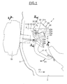
- a mounting device 1 of a brake pedal 2 is located behind an apron 3 of a motor vehicle with a floor 4.
- the floor 4 defines a so-called horizontal plane, the vertical direction being defined as a direction perpendicular to the plane horizontal.
- the front of the vehicle is considered to be the direction in which the vehicle is moving the vehicle in normal operation, the rear being the opposite direction.
- the upper part of the pedal 2 has a transverse bore 5 traversed by a rotation axis 6 (fig. 2) having ends of smaller diameter 6a, 6b protruding into orifices 7, 8 of longitudinal flanges respectively 9, 10 of a support 11 which extends rearwards from the apron 3 while being fixed on the latter of known manner, not shown.
- the flanges 9, 10 extend substantially parallel to the plane of Figure 1.
- the lower part of the brake pedal 2 comprises a support pad 21 on which the driver acts with the foot.
- one end 6a may include a flat 6c for angularly immobilizing the axis 6 relative to the flanges 9, 10.
- the brake pedal 2 is mounted on the axis of rotation 6 by means of a sleeve 12 extending axially on the side and other of the bore 5 of the brake pedal 2 and comprising two beads retaining rings 12a, 12b extending radially on either side of the pedal brake 2 to hold it axially.
- the beads 12a, 12b are axially offset on the sleeve 12 with respect to a radial plane of symmetry of the axis 6, to leave a portion 12c free, so that the brake pedal 2 is in the offset position on the sleeve 12.
- the sleeve 12 is itself mounted on the axis of rotation 6 by via a central tubular crown 13 and two tubular crowns end 14 and 15 located on either side of the central crown 13.
- the end rings 14, 15 comprise at their opposite ends flanges 16, 17 projecting outwards to axially retain the sleeve 12.
- the brake pedal 2 is connected by means of a lever articulated 19 to a braking member 18 to be controlled, located in front of the deck 3.
- the brake pedal 2 is rotatably mounted on the articulated lever 19 via an axis 20 perpendicular to the plane of Figure 1.
- a spacer 22 is mounted on the support 11 via a mechanical connection element in the form of an elongated elastic tab 23 having three straight portions 23a, 23b, 23c interconnected by portions curves, and substantially forming a Z.
- the tab 23 has a small thickness for give it some flexibility.
- the spacer 22 includes arms 24, 25 parallel (fig. 3, 4) extending in the plane of FIG. 1 while being in substantially planar contact with the flanges 9, 10.
- the arms 24, 25 are connected by a transverse wall 26 (fig. 3).
- the arms 24, 25 each include at their upper end support edges 27, 28 (fig. 1, 4) substantially vertical and oriented towards the rear.
- Each arm 24, 25 comprises at its lower end two legs 24a, 24b, 25a, 25b, (fig. 1, 2, 3) in projecting downwards and forming between them openings 24c, 25c respectively.
- the portion 23a of the tab 23 is fixed on a piece 34 of folded sheet metal extending transversely between the flanges 9, 10, being integral with the flanges 9, 10.
- the portion 23c opposite the portion 23a is fixed to the transverse wall 26 of the spacer 22.
- the spacer 22 is thus fixed on the support 11 while being able to pivot in the plane of Figure 1 and move substantially vertically with respect to the support 11, by deformation of the tab 23, facilitated by its flexibility.
- the spacer 22 is disposed between the flanges 9, 10.
- the ends 6a, 6b of the axis of rotation 6 are introduced into the openings 24c, 25c, between the tabs 24a and 24b, 25a, and 25b arranged substantially vertically.
- the forming openings 24c, 25c makes it easy to mount the spacer 22 rotating on the axis 6, by introducing the ends 6a, 6b of the axis 6 in the openings 24c, 25c, while the width of the openings 24c, 25c does not allow the passage of a central portion of axis 6.
- a first mounting step allows mount the axis 6 in the flanges 9, 10, the axis 6 being retained axially by the fact that it cannot pass through the openings 7, 8.
- the spacer 22 can be mounted when of a later step.
- a stop 29 (fig. 1) secured to a rear part of the vehicle not shown in the figures, comprises a substantially horizontal portion 30 and a oblique bearing portion 31 extending upwards on the side of the spacer 22, being located behind the arms 24, 25.
- the oblique portion 31 includes an edge free 31a opposite to the portion 30, and situated vertically at the height of the edges 27, 28 of the spacer 22.
- the flanges 9, 10 include recesses 32, 33 (fig. 2) located slightly in front of the axis of rotation 6, and under the spacer 22, and forming a zone of least transverse spacing between the flanges 9 and 10.
- the brake pedal 2 can pivot around the axis of rotation 6 in the direction of the arrow F1 to cause a movement of the articulated lever 19 forwards in order to control the braking 18.
- the rigidity of the flanges 9, 10 makes it possible to withstand the forces exerted in a vertical plane on axis 6, during normal operation of the braking, even when the driver presses hard on pad 21.
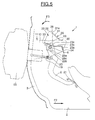
- Figures 5 to 7 illustrate successive stages of movement of the apron 3 towards the rear during a brutal impact causing a deformation of the structure of the vehicle.
- the apron 3 moves rearward in the direction of the arrow F2 and drives with it back the support 11 of the pedal 2.
- the stop 29 attached to the rear part does not move, or moves later than the apron 3, so that the apron 3 approaches the stop 29.
- the spacer 22 fixed on the support 11 moves backwards, and if the displacement is sufficiently large, the support edges 27, 28 of the arms 24, 25 come into contact on the bearing portion 31 of the stop 29.
- the support edges 27, 28 of the arms 24, 25 of the part spacer 22 came into contact with the free edge 31a of the support portion oblique 31.
- the spacer 22 is rotatably mounted on the axis 6 and fixed by an elastic tab 23 to the support 11, contact with the free edge 31a when a rearward movement of the spacer 22 causes the rotation of the spacer 22 around the axis of rotation 6 in the direction of arrow F3.
- the rotation of the spacer 22 is accompanied by a deformation of the tab 23 connecting the spacer 22 to the support 11, mainly located between the portions 23c and 23b.
- the spacer 22 slides between the flanges 9, 10 passing between the recesses 32, 33 forming a area of less transverse width.
- the flanges 9, 10, of small thickness and extending in vertical planes parallel to the plane of Figure 6, can be easily deformed in the transverse direction, perpendicular to the plane of Figure 6.
- the passage of the spacer 22 rigidified by the transverse wall 26 between the depressions 32, 33 cause the transverse spacing of the flanges 9, 10.
- the axis of rotation 6 having ends 6a, 6b of smaller diameter in projection in the openings 7, 8, is held transversely between the flanges 9, 10 in both directions, a member for retaining the axis of rotation 6 with the flanges 9, 10, for example a circlip, not being essential.
- the recesses 32, 33 are formed so that the passage of the part spacing 22 causes the deformation of the flanges 9, 10, until the ends 6a, 6b of the axis of rotation 6 disengage from the orifices 7, 8, and that the brake pedal 2 is released.
- the simple fixing of axis 6 does not hinder the transverse deformation of the flanges 9, 10 which can be done safely, the disengagement of the axis 6 with respect to the support 11 without breaking the part of fixation.
- FIG. 7 illustrates a position of displacement consecutive to a additional movement of the deck 3 backwards, in the direction of arrow F2.
- the edges 27, 28 have come into contact with the oblique wall 31.
- the edges 27, 28 then guide the movement of the part of spacing 22 by sliding on the oblique wall 31, and cause a displacement of the spacer 22 relative to the stop 29 in the direction of arrow F4, substantially parallel to the oblique wall 31.
- the tab 23 allows the movement of the spacer 22 relative to to the support 11, while maintaining the spacer 22 on the support 11, to drive the spacer 22 backwards with the support 11.
- the deformation of the tab 23 is accentuated, in particular between the portions 23b and 23a.
- the room of spacing 22 causes in its movement the axis of rotation 6, engaged in the openings 24c, 25c, and the brake pedal 2 rotatably mounted on the axis 6.
- the openings 24c, 25c are oriented in the direction of the displacement of the spacer 22, so that the displacement of the part 22 tends to cause a displacement of the axis 6 towards the closed bottom of the openings 24c, 25c.
- the spacer 22 therefore drives the axis of rotation 6 in its translational movement, in the direction of arrow F4.
- the brake pedal 2 is always linked to the articulated lever 19 via of the axis 20.
- the spacer 22, acting on the axis 6, creates a moment tending to rotate the brake pedal 2 around the axis 20 according to the direction indicated by arrow F5, so that the shoe 21 folds down towards the floor 4 in moving away from the driver's foot.
- the fixing device of pedal 2 thus successively causes the release of pedal 2 and erasing the pedal 2.
- the rotation of the spacer 22 causes first releasing pedal 2 securely, then moving the workpiece 22 guided by the stop 29 causes the erasure of the pedal 2.
- the transverse rigidity of the flanges 9, 10 authorizes the release of the brake pedal 2 by a deformation with a relatively low force ensuring a certain erasure of the brake pedal 2, without breaking a fixing part.
- the brake pedal can be detached from the support. when the apron moves backwards, in order to release the brake pedal for avoid a possible physiological lesion of the driver's ankle, without rupture a fixing piece.
- the spacer allows the brake pedal to be released by exerting a weak force, ensuring a certain erasure of the brake pedal in the event frontal impact.
- the brake pedal mounting device also proves to be simple, and uses a limited number of parts, which can be assembled so simple.
Landscapes
- Engineering & Computer Science (AREA)
- Transportation (AREA)
- Mechanical Engineering (AREA)
- Physics & Mathematics (AREA)
- General Physics & Mathematics (AREA)
- Automation & Control Theory (AREA)
- Mechanical Control Devices (AREA)
- Braking Elements And Transmission Devices (AREA)
Abstract
Description
- la figure 1 représente une vue en coupe schématique selon I-I de la figure 2 d'un dispositif de montage d'une pédale selon l'invention ;
- la figure 2 est une vue en coupe sensiblement horizontale d'une partie du dispositif de montage de la figure 1 selon II-II;
- la figure 3 est une vue en coupe sensiblement verticale d'une partie du dispositif de montage de la figure 1 selon III-III;
- la figure 4 est une vue en perspective partielle du dispositif de montage de la figure 1 ;
- la figure 5 est une vue schématique du dispositif de montage selon la figure 1, dans une première position lors d'un choc frontal entraínant une déformation du tablier du véhicule ;
- la figure 6 est une vue schématique d'une seconde position du dispositif selon la figure 1 lors d'un choc frontal, consécutive à une déformation supplémentaire du tablier du véhicule ; et
- la figure 7 est une vue schématique d'une troisième position du dispositif de montage selon la figure 1 lors d'un choc frontal, consécutive à une déformation supplémentaire du tablier du véhicule, par rapport à la position de la figure 6.
Claims (8)
- Dispositif de montage d'une pédale de véhicule automobile, en particulier d'une pédale de frein, comprenant un support (11) sur lequel est montée la pédale (2) par l'intermédiaire d'un axe de rotation (6) engagé dans des orifices (7, 8) aménagés dans des flasques (9, 10) du support (11), caractérisé par le fait qu'il comprend des moyens de désengagement de l'axe de rotation (6) et du support (11) par déformation du support (11) coopérant avec une partie de la structure du véhicule située à l'arrière relativement au support (11) pour libérer la pédale (2) du support (11) en cas de déplacement dudit support (11) par rapport à ladite partie arrière.
- Dispositif selon la revendication 1, caractérisé par le fait qu'il comprend des moyens capables de provoquer l'écartement des flasques (9, 10) du support jusqu'au désengagement des extrémités (6a, 6b) de l'axe de rotation (6) des orifices (7, 8) des flasques (9, 10).
- Dispositif selon la revendication 2, caractérisé par le fait que les flasques (9, 10) du support comprennent des enfoncements (32, 33) en saillie dans un espace compris entre les flasques (9, 10).
- Dispositif selon l'une quelconque des revendications 2 ou 3, caractérisé par le fait qu'il comprend une pièce d'écartement (22) des flasques (9, 10) disposée entre les flasques (9, 10).
- Dispositif selon la revendication 4, caractérisé par le fait qu'il comprend des moyens pour déplacer la pièce d'écartement (22) entre les flasques (9, 10) lors d'un déplacement du support (9) par rapport à la partie arrière.
- Dispositif selon l'une quelconque des revendications 4 ou 5, caractérisé par le fait que la pièce d'écartement (20) est fixée au support (11) par une patte élastique (23).
- Dispositif selon l'une quelconque des revendications 4 à 6, caractérisé par le fait que la pièce d'écartement (22) comprend des bras (24, 25) destinés à coopérer avec une butée (29) solidaire de la partie arrière en cas de déplacement du support (11) par rapport à la partie arrière.
- Dispositif selon l'une quelconque des revendications 4 à 7, caractérisé par le fait que la pièce d'écartement (22) est disposée à rotation sur l'axe de rotation (6).
Applications Claiming Priority (2)
| Application Number | Priority Date | Filing Date | Title |
|---|---|---|---|
| FR0113751 | 2001-10-24 | ||
| FR0113751A FR2831125B1 (fr) | 2001-10-24 | 2001-10-24 | Dispositif de montage d'une pedale dans un vehicule |
Publications (2)
| Publication Number | Publication Date |
|---|---|
| EP1308357A1 true EP1308357A1 (fr) | 2003-05-07 |
| EP1308357B1 EP1308357B1 (fr) | 2009-07-01 |
Family
ID=8868669
Family Applications (1)
| Application Number | Title | Priority Date | Filing Date |
|---|---|---|---|
| EP20020292578 Expired - Lifetime EP1308357B1 (fr) | 2001-10-24 | 2002-10-18 | Dispositif de montage d'une pédale dans un véhicule |
Country Status (3)
| Country | Link |
|---|---|
| EP (1) | EP1308357B1 (fr) |
| DE (1) | DE60232770D1 (fr) |
| FR (1) | FR2831125B1 (fr) |
Cited By (3)
| Publication number | Priority date | Publication date | Assignee | Title |
|---|---|---|---|---|
| US8474348B2 (en) | 2010-02-04 | 2013-07-02 | Ksr Technologies Co. | Pedal assembly for electronic braking system |
| US8806976B2 (en) | 2010-02-04 | 2014-08-19 | Ksr Technologies Co. | Brake pedal assembly having non-contacting sensor |
| US8973462B2 (en) | 2012-03-15 | 2015-03-10 | Ksr Ip Holdings Llc. | Pedal assembly having a pedal arm release |
Families Citing this family (1)
| Publication number | Priority date | Publication date | Assignee | Title |
|---|---|---|---|---|
| FR3011350B1 (fr) * | 2013-09-27 | 2015-10-16 | Peugeot Citroen Automobiles Sa | Ensemble de pedale d'un vehicule automobile |
Citations (4)
| Publication number | Priority date | Publication date | Assignee | Title |
|---|---|---|---|---|
| DE19501680A1 (de) * | 1995-01-20 | 1996-08-08 | Schmidt Gmbh R | Fußhebelwerk für ein Kraftfahrzeug |
| EP0965506A1 (fr) | 1998-06-17 | 1999-12-22 | Renault | Dispositif de montage d'une pédale d'un véhicule automobile |
| US6112616A (en) * | 1996-02-22 | 2000-09-05 | Itt Manufacturing Enterprises, Inc. | Brake pedal mechanism for automotive vehicles |
| DE10028117A1 (de) * | 1999-06-04 | 2000-12-07 | Suzuki Motor Co | Pedalhalterungskonstruktion |
-
2001
- 2001-10-24 FR FR0113751A patent/FR2831125B1/fr not_active Expired - Fee Related
-
2002
- 2002-10-18 DE DE60232770T patent/DE60232770D1/de not_active Expired - Lifetime
- 2002-10-18 EP EP20020292578 patent/EP1308357B1/fr not_active Expired - Lifetime
Patent Citations (4)
| Publication number | Priority date | Publication date | Assignee | Title |
|---|---|---|---|---|
| DE19501680A1 (de) * | 1995-01-20 | 1996-08-08 | Schmidt Gmbh R | Fußhebelwerk für ein Kraftfahrzeug |
| US6112616A (en) * | 1996-02-22 | 2000-09-05 | Itt Manufacturing Enterprises, Inc. | Brake pedal mechanism for automotive vehicles |
| EP0965506A1 (fr) | 1998-06-17 | 1999-12-22 | Renault | Dispositif de montage d'une pédale d'un véhicule automobile |
| DE10028117A1 (de) * | 1999-06-04 | 2000-12-07 | Suzuki Motor Co | Pedalhalterungskonstruktion |
Cited By (4)
| Publication number | Priority date | Publication date | Assignee | Title |
|---|---|---|---|---|
| US8474348B2 (en) | 2010-02-04 | 2013-07-02 | Ksr Technologies Co. | Pedal assembly for electronic braking system |
| US8806976B2 (en) | 2010-02-04 | 2014-08-19 | Ksr Technologies Co. | Brake pedal assembly having non-contacting sensor |
| US9616861B2 (en) | 2010-02-04 | 2017-04-11 | Ksr Ip Holdings Llc. | Pedal assembly for electronic braking system |
| US8973462B2 (en) | 2012-03-15 | 2015-03-10 | Ksr Ip Holdings Llc. | Pedal assembly having a pedal arm release |
Also Published As
| Publication number | Publication date |
|---|---|
| EP1308357B1 (fr) | 2009-07-01 |
| DE60232770D1 (de) | 2009-08-13 |
| FR2831125A1 (fr) | 2003-04-25 |
| FR2831125B1 (fr) | 2004-01-16 |
Similar Documents
| Publication | Publication Date | Title |
|---|---|---|
| EP3265687B1 (fr) | Frein a disque comportant au moins un ressort de rappel elastique d'un patin de freinage, ressort de rappel elastique, glissiere de guidage et kit de remplacement | |
| EP1479578B1 (fr) | Dispositif de pédalier rétractable en cas de choc frontal sur un véhicule | |
| EP0947380B1 (fr) | Dispositif de crémaillère rapportée en fond de glissière | |
| FR2944115A1 (fr) | Pedale de vehicule automobile avec dispositif de mise en securite. | |
| EP0949111B1 (fr) | Système d'arrimage modulable à commande par cames | |
| EP2701953A1 (fr) | Dispositif de montage d'une pedale d'un vehicule automobile | |
| FR3043027A1 (fr) | Siege de vehicule | |
| EP0965506B1 (fr) | Dispositif de montage d'une pédale d'un véhicule automobile | |
| EP3095684B1 (fr) | Patte de derailleur | |
| FR3025756A1 (fr) | Glissieres pour sieges de vehicules, siege de vehicule comportant une telle glissiere | |
| EP1247710A1 (fr) | Ensemble de pédale de frein pour un véhicule automobile | |
| EP1308357B1 (fr) | Dispositif de montage d'une pédale dans un véhicule | |
| EP2930130A1 (fr) | Dispositif de cale d'immobilisation de vehicule | |
| EP0747256B1 (fr) | Siège orientable de sécurité pour un véhicule tel qu'un aéronef | |
| FR2689825A1 (fr) | Appui-tête pour siège de véhicule automobile. | |
| EP0543706B1 (fr) | Dispositif d'accrochage automatique au plancher d'un véhicule d'un moyen de fixation d'une ceinture de sécurité | |
| EP1243491A1 (fr) | Dispositif de montage d'une pédale dans un véhicule | |
| FR3128162A1 (fr) | Ouvrant de véhicule comprenant un moyen de blocage de la serrure en cas de choc. | |
| FR2832105A1 (fr) | Siege de vehicule comprenant un dispositif d'assistance et vehicule equipe d'un tel siege | |
| EP3452359B1 (fr) | Interface de montage d'une colonne de direction et procede de montage associe | |
| EP2388492B1 (fr) | Dispositif d'assistance à la pédale de débrayage d'un véhicule automobile | |
| EP1547858A1 (fr) | Accoudoir pour siège de véhicule automobile, console et siège portant cet accoudoir | |
| FR3071785B1 (fr) | Structure de siege de vehicule automobile dotee d’une agrafe de maintien d’un carter de recouvrement. | |
| WO2016030639A1 (fr) | Siège pour véhicule comprenant un plancher de chargement | |
| FR2819758A1 (fr) | Dispositif de securisation d'un pedalier de vehicule |
Legal Events
| Date | Code | Title | Description |
|---|---|---|---|
| PUAI | Public reference made under article 153(3) epc to a published international application that has entered the european phase |
Free format text: ORIGINAL CODE: 0009012 |
|
| AK | Designated contracting states |
Designated state(s): AT BE BG CH CY CZ DE DK EE ES FI FR GB GR IE IT LI LU MC NL PT SE SK TR |
|
| AX | Request for extension of the european patent |
Extension state: AL LT LV MK RO SI |
|
| AKX | Designation fees paid | ||
| REG | Reference to a national code |
Ref country code: DE Ref legal event code: 8566 |
|
| 17P | Request for examination filed |
Effective date: 20031111 |
|
| RBV | Designated contracting states (corrected) |
Designated state(s): BE DE FR GB |
|
| R17P | Request for examination filed (corrected) |
Effective date: 20031106 |
|
| RBV | Designated contracting states (corrected) |
Designated state(s): BE DE FR GB |
|
| 17Q | First examination report despatched |
Effective date: 20080922 |
|
| GRAP | Despatch of communication of intention to grant a patent |
Free format text: ORIGINAL CODE: EPIDOSNIGR1 |
|
| GRAS | Grant fee paid |
Free format text: ORIGINAL CODE: EPIDOSNIGR3 |
|
| GRAA | (expected) grant |
Free format text: ORIGINAL CODE: 0009210 |
|
| AK | Designated contracting states |
Kind code of ref document: B1 Designated state(s): BE DE FR GB |
|
| REG | Reference to a national code |
Ref country code: GB Ref legal event code: FG4D Free format text: NOT ENGLISH |
|
| REF | Corresponds to: |
Ref document number: 60232770 Country of ref document: DE Date of ref document: 20090813 Kind code of ref document: P |
|
| BERE | Be: lapsed |
Owner name: RENAULT S.A.S. Effective date: 20091031 |
|
| PLBE | No opposition filed within time limit |
Free format text: ORIGINAL CODE: 0009261 |
|
| STAA | Information on the status of an ep patent application or granted ep patent |
Free format text: STATUS: NO OPPOSITION FILED WITHIN TIME LIMIT |
|
| 26N | No opposition filed |
Effective date: 20100406 |
|
| PG25 | Lapsed in a contracting state [announced via postgrant information from national office to epo] |
Ref country code: BE Free format text: LAPSE BECAUSE OF NON-PAYMENT OF DUE FEES Effective date: 20091031 |
|
| REG | Reference to a national code |
Ref country code: FR Ref legal event code: PLFP Year of fee payment: 14 |
|
| REG | Reference to a national code |
Ref country code: FR Ref legal event code: PLFP Year of fee payment: 15 |
|
| PGFP | Annual fee paid to national office [announced via postgrant information from national office to epo] |
Ref country code: FR Payment date: 20161020 Year of fee payment: 15 Ref country code: GB Payment date: 20161020 Year of fee payment: 15 Ref country code: DE Payment date: 20161020 Year of fee payment: 15 |
|
| REG | Reference to a national code |
Ref country code: DE Ref legal event code: R119 Ref document number: 60232770 Country of ref document: DE |
|
| GBPC | Gb: european patent ceased through non-payment of renewal fee |
Effective date: 20171018 |
|
| REG | Reference to a national code |
Ref country code: FR Ref legal event code: ST Effective date: 20180629 |
|
| PG25 | Lapsed in a contracting state [announced via postgrant information from national office to epo] |
Ref country code: GB Free format text: LAPSE BECAUSE OF NON-PAYMENT OF DUE FEES Effective date: 20171018 Ref country code: DE Free format text: LAPSE BECAUSE OF NON-PAYMENT OF DUE FEES Effective date: 20180501 |
|
| PG25 | Lapsed in a contracting state [announced via postgrant information from national office to epo] |
Ref country code: FR Free format text: LAPSE BECAUSE OF NON-PAYMENT OF DUE FEES Effective date: 20171031 |