EP1308199B1 - Waste gas treating device having flow regulator - Google Patents
Waste gas treating device having flow regulator Download PDFInfo
- Publication number
- EP1308199B1 EP1308199B1 EP01953324A EP01953324A EP1308199B1 EP 1308199 B1 EP1308199 B1 EP 1308199B1 EP 01953324 A EP01953324 A EP 01953324A EP 01953324 A EP01953324 A EP 01953324A EP 1308199 B1 EP1308199 B1 EP 1308199B1
- Authority
- EP
- European Patent Office
- Prior art keywords
- baffle
- exhaust gas
- lattice
- catalyst
- duct
- Prior art date
- Legal status (The legal status is an assumption and is not a legal conclusion. Google has not performed a legal analysis and makes no representation as to the accuracy of the status listed.)
- Expired - Lifetime
Links
- 239000002912 waste gas Substances 0.000 title 1
- 239000003054 catalyst Substances 0.000 claims abstract description 77
- 230000005465 channeling Effects 0.000 abstract description 2
- 230000000694 effects Effects 0.000 description 4
- 238000000034 method Methods 0.000 description 4
- 230000007423 decrease Effects 0.000 description 2
- 230000015572 biosynthetic process Effects 0.000 description 1
- 238000002485 combustion reaction Methods 0.000 description 1
- -1 dioxins Chemical class 0.000 description 1
- 150000002013 dioxins Chemical class 0.000 description 1
- 239000010881 fly ash Substances 0.000 description 1
- 150000002366 halogen compounds Chemical class 0.000 description 1
- 231100001261 hazardous Toxicity 0.000 description 1
Images



Classifications
-
- B—PERFORMING OPERATIONS; TRANSPORTING
- B01—PHYSICAL OR CHEMICAL PROCESSES OR APPARATUS IN GENERAL
- B01D—SEPARATION
- B01D53/00—Separation of gases or vapours; Recovering vapours of volatile solvents from gases; Chemical or biological purification of waste gases, e.g. engine exhaust gases, smoke, fumes, flue gases, aerosols
- B01D53/34—Chemical or biological purification of waste gases
- B01D53/74—General processes for purification of waste gases; Apparatus or devices specially adapted therefor
- B01D53/86—Catalytic processes
- B01D53/8696—Controlling the catalytic process
-
- B—PERFORMING OPERATIONS; TRANSPORTING
- B01—PHYSICAL OR CHEMICAL PROCESSES OR APPARATUS IN GENERAL
- B01D—SEPARATION
- B01D53/00—Separation of gases or vapours; Recovering vapours of volatile solvents from gases; Chemical or biological purification of waste gases, e.g. engine exhaust gases, smoke, fumes, flue gases, aerosols
- B01D53/34—Chemical or biological purification of waste gases
- B01D53/74—General processes for purification of waste gases; Apparatus or devices specially adapted therefor
- B01D53/86—Catalytic processes
-
- B—PERFORMING OPERATIONS; TRANSPORTING
- B01—PHYSICAL OR CHEMICAL PROCESSES OR APPARATUS IN GENERAL
- B01D—SEPARATION
- B01D53/00—Separation of gases or vapours; Recovering vapours of volatile solvents from gases; Chemical or biological purification of waste gases, e.g. engine exhaust gases, smoke, fumes, flue gases, aerosols
- B01D53/34—Chemical or biological purification of waste gases
- B01D53/74—General processes for purification of waste gases; Apparatus or devices specially adapted therefor
- B01D53/86—Catalytic processes
- B01D53/88—Handling or mounting catalysts
- B01D53/885—Devices in general for catalytic purification of waste gases
-
- B—PERFORMING OPERATIONS; TRANSPORTING
- B01—PHYSICAL OR CHEMICAL PROCESSES OR APPARATUS IN GENERAL
- B01J—CHEMICAL OR PHYSICAL PROCESSES, e.g. CATALYSIS OR COLLOID CHEMISTRY; THEIR RELEVANT APPARATUS
- B01J8/00—Chemical or physical processes in general, conducted in the presence of fluids and solid particles; Apparatus for such processes
- B01J8/008—Details of the reactor or of the particulate material; Processes to increase or to retard the rate of reaction
- B01J8/0085—Details of the reactor or of the particulate material; Processes to increase or to retard the rate of reaction promoting uninterrupted fluid flow, e.g. by filtering out particles in front of the catalyst layer
-
- B—PERFORMING OPERATIONS; TRANSPORTING
- B01—PHYSICAL OR CHEMICAL PROCESSES OR APPARATUS IN GENERAL
- B01J—CHEMICAL OR PHYSICAL PROCESSES, e.g. CATALYSIS OR COLLOID CHEMISTRY; THEIR RELEVANT APPARATUS
- B01J8/00—Chemical or physical processes in general, conducted in the presence of fluids and solid particles; Apparatus for such processes
- B01J8/02—Chemical or physical processes in general, conducted in the presence of fluids and solid particles; Apparatus for such processes with stationary particles, e.g. in fixed beds
- B01J8/0242—Chemical or physical processes in general, conducted in the presence of fluids and solid particles; Apparatus for such processes with stationary particles, e.g. in fixed beds the fluid flow within the bed being predominantly vertical
- B01J8/025—Chemical or physical processes in general, conducted in the presence of fluids and solid particles; Apparatus for such processes with stationary particles, e.g. in fixed beds the fluid flow within the bed being predominantly vertical in a cylindrical shaped bed
-
- B—PERFORMING OPERATIONS; TRANSPORTING
- B01—PHYSICAL OR CHEMICAL PROCESSES OR APPARATUS IN GENERAL
- B01J—CHEMICAL OR PHYSICAL PROCESSES, e.g. CATALYSIS OR COLLOID CHEMISTRY; THEIR RELEVANT APPARATUS
- B01J8/00—Chemical or physical processes in general, conducted in the presence of fluids and solid particles; Apparatus for such processes
- B01J8/02—Chemical or physical processes in general, conducted in the presence of fluids and solid particles; Apparatus for such processes with stationary particles, e.g. in fixed beds
- B01J8/0278—Feeding reactive fluids
-
- F—MECHANICAL ENGINEERING; LIGHTING; HEATING; WEAPONS; BLASTING
- F23—COMBUSTION APPARATUS; COMBUSTION PROCESSES
- F23J—REMOVAL OR TREATMENT OF COMBUSTION PRODUCTS OR COMBUSTION RESIDUES; FLUES
- F23J15/00—Arrangements of devices for treating smoke or fumes
- F23J15/02—Arrangements of devices for treating smoke or fumes of purifiers, e.g. for removing noxious material
-
- F—MECHANICAL ENGINEERING; LIGHTING; HEATING; WEAPONS; BLASTING
- F23—COMBUSTION APPARATUS; COMBUSTION PROCESSES
- F23M—CASINGS, LININGS, WALLS OR DOORS SPECIALLY ADAPTED FOR COMBUSTION CHAMBERS, e.g. FIREBRIDGES; DEVICES FOR DEFLECTING AIR, FLAMES OR COMBUSTION PRODUCTS IN COMBUSTION CHAMBERS; SAFETY ARRANGEMENTS SPECIALLY ADAPTED FOR COMBUSTION APPARATUS; DETAILS OF COMBUSTION CHAMBERS, NOT OTHERWISE PROVIDED FOR
- F23M3/00—Firebridges
- F23M3/02—Firebridges modified for circulation of fluids, e.g. air, steam, water
- F23M3/04—Firebridges modified for circulation of fluids, e.g. air, steam, water for delivery of gas, e.g. air, steam
- F23M3/08—Firebridges modified for circulation of fluids, e.g. air, steam, water for delivery of gas, e.g. air, steam away from fire, e.g. towards smoke outlet
-
- F—MECHANICAL ENGINEERING; LIGHTING; HEATING; WEAPONS; BLASTING
- F23—COMBUSTION APPARATUS; COMBUSTION PROCESSES
- F23J—REMOVAL OR TREATMENT OF COMBUSTION PRODUCTS OR COMBUSTION RESIDUES; FLUES
- F23J2219/00—Treatment devices
- F23J2219/10—Catalytic reduction devices
Definitions
- the present invention relates to an apparatus having a baffle device and used for treating an exhaust gas. More specifically, the present invention relates to an apparatus having a baffle lattice at the inlet of a catalyst device to improve the distribution of the flow rates of an exhaust gas in the catalyst device, and used for treating an exhaust gas, especially for denitrating an exhaust gas.
- FIG. 7 is an illustration of a structure of a device in the vicinity of a denitrating device installed in a duct used for an exhaust gas generated from such a combustion apparatus as described above, including an enlarged illustration of a part of the device.
- This apparatus comprises inlet duct 1 through which exhaust gas G is flowed in, catalyst duct 9 in which denitrating catalyst layer 4 is disposed, bend portion 2 which connects the inlet duct 1 and the catalyst duct 9, baffle lattice 3 disposed at the inlet of the catalyst duct 9 in the direction of the cross section of the duct, and beams 6 which directly support the baffle lattice 3.
- exhaust gas G reaches, through inlet duct 1, to bend portion 2 formed at a midway of an exhaust gas duct, changes there its flow direction by 90°, flows into catalyst layer 4 disposed in catalyst duct 9 through baffle lattice 3, and then reaches to outlet duct 5 after subjected to a denitration.
- FIG. 7 the distribution of gas flow rates at the inlet of catalyst layer 4 is shown, and the distribution indicates that the flow rates of an exhaust gas are nonuniform in the direction of the cross section of the catalyst duct 9. Accordingly, it has been strongly desired or requested that
- baffle lattice 3 is disposed at the inlet of catalyst duct 9 (catalyst duct 10 in Japanese Patent No. 2637119), the baffle lattice 3 is provided with an outer frame having the same height as that of the baffle lattice, and further, beams 6 used for directly supporting the baffle lattice 3 and for preventing the reactor from being deformed are disposed so that the lower ends of plates of the baffle lattice 3 contact with the upper surfaces of upper flanges of the beams 6 as shown in the enlarged portion of Fig. 7. In this structure, however, the beams 6 used for directly supporting the baffle lattice partially block the exhaust gas flow passages in the baffle lattice 3.
- Subject of the present invention is to provide a structure of a baffle device for preventing occurrence of a channelling (nonuniform flow) of an exhaust gas to be flowed into a catalyst duct in an apparatus which is used for treating the exhaust gas and comprises an inlet duct through which the exhaust gas is flowed in, a bend portion, and a catalyst duct connected to the inlet duct through the bend portion and having a catalyst disposed in the duct and used for purifying the exhaust gas, and which apparatus further has a baffle lattice disposed at the inlet of the catalyst duct in the direction of the cross section of the duct.
- the shape of a baffle lattice provided in a catalyst duct having a catalyst layer disposed therein may be a lattice-like, honeycomb-like, or any other shape so far as the baffle lattice is arranged at the inlet of the catalyst duct in the direction of the cross section of the catalyst duct.
- the catalyst used for the catalyst layer 4 disposed in the catalyst duct 6 in the apparatus of the present invention is not limited to a denitrating catalyst, and it may be a catalyst used for treating an exhaust gas containing hazardous halogen compounds such as dioxins, or another catalyst.
- FIG. 1 is an illustration showing the structure of a device in the vicinity of a denitrating device in an example of exhaust gas treating apparatuses of the present invention, including an enlarged illustration of a part of the device.
- This apparatus comprises inlet duct 1 through which exhaust gas G is flowed in, bend portion 2, catalyst duct 9 connected to the inlet duct through the bend portion and having layer 4 of a denitrating catalyst therein, baffle lattice 3 disposed at the inlet of the catalyst duct 9 in the direction of the cross section of the duct and having a height of A, outer frame 7 used for supporting the baffle lattice and having a height B which is larger than the height A, and beams 6 disposed in parallel to the rectangular plates, which plates form the baffle lattice, and used for supporting by turn the outer frame 7 provided to the lower ends of the outer frame.
- Catalyst duct 9 having catalyst layer 4 disposed therein is arranged so that the direction of the catalyst duct and that of inlet duct 1 intersect with each other at right angles, and both of the ducts are connected through bend portion 2 to form a structure. Then, outer casing 2a of the bend portion is formed such that intersecting point X of the extremity of the bend portion with the extension line of floor (bottom) surface 1a of the inlet duct 1 is connected through a straight line to intersecting point Y of extension line of the wall surface at the inlet duct side of the catalyst duct with ceiling portion 1b of inlet duct 1.
- Baffle lattice 3 is arranged so that the level of its upper ends become about the same with the level of floor surface 1a of the inlet duct at the inlet portion of catalyst duct 9.
- baffle lattice 3 rectangular plates having a height of A are arranged in parallel with each other as shown in the Figures, and outer frame 7 having a height of B is provided outside the baffle lattice 3.
- the outer frame 7 of the baffle lattice is arranged so that the level of upper ends of the frame become about the same with the upper ends of baffle lattice 3, and the outer frame is designed so that the height B of the frame is larger than the height A of baffle lattice 3 as shown in Fig. 2.
- Beams 6 used for supporting the outer frame of the baffle lattice are arranged so that the level of the lower ends of outer frame 7 become the same with that of the upper surfaces of upper flanges of the beams 6, and the beams and frames form a structure in which the beams are arranged in parallel to the rectangular plates of the baffle lattice, and support the outer frame 7 of the lattice.
- a couple of baffle plates 8 each having an elevation angle of ⁇ are provided over the entire length of extending beams excluding the portions where flanges of beams 6 contact with the outer frame 7.
- the angle ⁇ of the baffle plates is in the range which satisfies the equation 0° ⁇ ⁇ ⁇ 90°.
- Fig. 3 the flow state of an exhaust gas in an apparatus of the present invention having the structure as described above is shown.
Landscapes
- Engineering & Computer Science (AREA)
- Chemical & Material Sciences (AREA)
- Chemical Kinetics & Catalysis (AREA)
- Environmental & Geological Engineering (AREA)
- Organic Chemistry (AREA)
- Health & Medical Sciences (AREA)
- Biomedical Technology (AREA)
- Analytical Chemistry (AREA)
- General Chemical & Material Sciences (AREA)
- Oil, Petroleum & Natural Gas (AREA)
- General Engineering & Computer Science (AREA)
- Mechanical Engineering (AREA)
- Physics & Mathematics (AREA)
- Fluid Mechanics (AREA)
- Combustion & Propulsion (AREA)
- Exhaust Gas Treatment By Means Of Catalyst (AREA)
- Exhaust Gas After Treatment (AREA)
- Chimneys And Flues (AREA)
- Devices And Processes Conducted In The Presence Of Fluids And Solid Particles (AREA)
- Physical Or Chemical Processes And Apparatus (AREA)
- Diaphragms For Electromechanical Transducers (AREA)
- Exposure Of Semiconductors, Excluding Electron Or Ion Beam Exposure (AREA)
- Sampling And Sample Adjustment (AREA)
- Feeding, Discharge, Calcimining, Fusing, And Gas-Generation Devices (AREA)
Abstract
Description
- The present invention relates to an apparatus having a baffle device and used for treating an exhaust gas. More specifically, the present invention relates to an apparatus having a baffle lattice at the inlet of a catalyst device to improve the distribution of the flow rates of an exhaust gas in the catalyst device, and used for treating an exhaust gas, especially for denitrating an exhaust gas.
- Heretofore, in large-sized boilers for thermal power plants, a large apparatus for treating an exhaust gas, such as a denitrating apparatus is installed. Fig. 7 is an illustration of a structure of a device in the vicinity of a denitrating device installed in a duct used for an exhaust gas generated from such a combustion apparatus as described above, including an enlarged illustration of a part of the device. This apparatus comprises
inlet duct 1 through which exhaust gas G is flowed in,catalyst duct 9 in which denitratingcatalyst layer 4 is disposed,bend portion 2 which connects theinlet duct 1 and thecatalyst duct 9,baffle lattice 3 disposed at the inlet of thecatalyst duct 9 in the direction of the cross section of the duct, andbeams 6 which directly support thebaffle lattice 3. In this apparatus, exhaust gas G reaches, throughinlet duct 1, to bendportion 2 formed at a midway of an exhaust gas duct, changes there its flow direction by 90°, flows intocatalyst layer 4 disposed incatalyst duct 9 throughbaffle lattice 3, and then reaches tooutlet duct 5 after subjected to a denitration. In the Fig. 7, the distribution of gas flow rates at the inlet ofcatalyst layer 4 is shown, and the distribution indicates that the flow rates of an exhaust gas are nonuniform in the direction of the cross section of thecatalyst duct 9. Accordingly, it has been strongly desired or requested that - (i) an exhaust gas flows into
catalyst layer 4 as uniformly as possible and - (ii) the flow of an exhaust gas which moves into
catalyst layer 4 and the flow of the exhaust gas in thecatalyst layer 4 become the same as much as possible, namely, the pattern of the flow passages of an exhaust gas immediately prior to flowing intocatalyst layer 4 agrees with the pattern of the flow passages formed in thecatalyst layer 4 for the exhaust gas. These desires are produced based on the following reasons: - That is, (i) the reason why the flowing of an exhaust
gas into
catalyst layer 4 is desired to be as uniform as possible is to efficiently increase the area in which the exhaust gas contacts with the catalyst in thecatalyst layer 4. If the flowing of the exhaust gas into the catalyst layer was not uniform, specific portions of the catalyst in thecatalyst layer 4 contact with a large amount of the exhaust gas and thus the performances of the catalyst decrease as a whole. Besides, there exists such a problem as the portions of the catalyst which contact with a large amount of the exhaust gas remarkably deteriorate and thus the life of the catalyst becomes short. - Next, (ii) the reason why the flow of an exhaust gas
moving into
catalyst layer 4 is desired to agree with the flow of the exhaust gas in thecatalyst layer 4 as much as possible is that, for instance, when dusts such as fly ashes and unburnt matters are contained in the exhaust gas, the exhaust gas sometimes obliquely flows into flow passages formed among catalysts (catalyst plates) in the catalyst layer for the exhaust gas, and thus (a) the dusts directly collide against the catalyst plates to wear their surfaces and (b) the dusts adhere to and deposit on the front portions of the catalyst plates to impede the flow of the succeeding exhaust gas into the flow passages. -
- In order to resolve the problems described in (i) and (ii) above, a method in which
baffle lattice 3 is disposed at the inlet of a catalyst duct (Japanese Patent No. 2637119) and another method in which a baffle device having baffle plates formed both at the upper stream side (on the upper flange) and the down stream side (on the lower flange) of a beam is provided at the inlet of a reactor (Laid open Japanese Utility Model Publication No. Sho 59-102134) are proposed. - In the former method described above,
baffle lattice 3 is disposed at the inlet of catalyst duct 9 (catalyst duct 10 in Japanese Patent No. 2637119), thebaffle lattice 3 is provided with an outer frame having the same height as that of the baffle lattice, and further,beams 6 used for directly supporting thebaffle lattice 3 and for preventing the reactor from being deformed are disposed so that the lower ends of plates of thebaffle lattice 3 contact with the upper surfaces of upper flanges of thebeams 6 as shown in the enlarged portion of Fig. 7. In this structure, however, thebeams 6 used for directly supporting the baffle lattice partially block the exhaust gas flow passages in thebaffle lattice 3. Besides, the cross sectional area in the direction perpendicular to the flow direction of an exhaust gas ininlet duct 1 decreases in thebend portion 2. As the result, the exhaust gas which was originally expected to flow through the flow passages blocked with thebeams 6 used for directly supporting the baffle lattice flows into flow passages positioned at the side ofinlet duct 1 of thebeams 6 to produce local high gas flow rate regions on the catalyst layer (see the distribution of gas flow rates in Fig. 7). On the other hand, in the method in which the baffle device having baffle plates both on the upper flange and lower flange of the beam is disposed at the inlet of a reactor, baffle effect is insufficient. - Subject of the present invention is to provide a structure of a baffle device for preventing occurrence of a channelling (nonuniform flow) of an exhaust gas to be flowed into a catalyst duct in an apparatus
which is used for treating the exhaust gas and comprises an inlet duct through which the exhaust gas is flowed in, a bend portion, and a catalyst duct connected to the inlet duct through the bend portion and having a catalyst disposed in the duct and used for purifying the exhaust gas, and
which apparatus further has a baffle lattice disposed at the inlet of the catalyst duct in the direction of the cross section of the duct. - In order to achieve the subject described above, the present invention is summarized as follows:
- (1) An apparatus having a baffle device and used for
treating an exhaust gas, the apparatus comprising:
- (a) an inlet duct through which the exhaust gas is flowed in,
- (b) a bend portion, and
- (c) a catalyst duct connected to the inlet duct through the bend portion and having a catalyst disposed therein and used for purifying the exhaust gas, and the baffle device being a baffle lattice having a height of A and disposed at the inlet of the catalyst duct in the direction of the cross section of the catalyst duct,
- (2) The apparatus for treating an exhaust gas recited in
paragraph (1) above wherein baffle plates comprising a pair
of flat plates are provided in counter relationship both on
the upper surfaces of upper flanges and the lower surfaces of
lower flanges of the beams used for supporting the baffle
lattice so that the angle α formed between the surfaces of
the baffle plates and the upper or lower surfaces of the
upper or lower flanges of the beams satisfies the following
equation.
- (3) The apparatus for treating an exhaust gas recited in
paragraph (1) above wherein baffle plates comprising a pair
of flat plates are provided in counter relationship only on
the upper surfaces of upper flanges or the lower surfaces of
lower flanges of the beams used for supporting the baffle
lattice so that the angle α formed between the surfaces of
the baffle plates and the upper or lower surfaces of the
upper or lower flanges of the beams satisfies the following
equation.
-
- In the apparatus of the present invention used for treating an exhaust gas, the shape of a baffle lattice provided in a catalyst duct having a catalyst layer disposed therein may be a lattice-like, honeycomb-like, or any other shape so far as the baffle lattice is arranged at the inlet of the catalyst duct in the direction of the cross section of the catalyst duct. Further, the catalyst used for the
catalyst layer 4 disposed in thecatalyst duct 6 in the apparatus of the present invention is not limited to a denitrating catalyst, and it may be a catalyst used for treating an exhaust gas containing hazardous halogen compounds such as dioxins, or another catalyst. -
- Fig. 1 is an illustration showing the structure of a device in the vicinity of a denitrating device in an example of exhaust gas treating apparatuses of the present invention, including an enlarged illustration of a part of the device.
- Fig. 2 is a perspective view of the outer frame of the baffle lattice used in the apparatus shown in Fig. 1.
- Fig. 3 is an illustration similar to that in Fig. 1 and additionally shows the state of the flow rate distribution of an exhaust gas in the apparatus shown in Fig. 1.
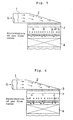
- Fig. 4 is an illustration similar to that in Fig. 3 with the exception that baffle plates are provided only on the upper side (on the upper surfaces of upper flanges) of the beams used for supporting the outer frame of the baffle lattice.
- Fig. 5 is an illustration similar to that in Fig. 3 with the exception that baffle plates are provided only on the lower side (on the lower surfaces of lower flanges) of the beams used for supporting the outer frame of the baffle lattice.
- Fig. 6 is an illustration similar to that in Fig. 3 with the exception that no baffle plates are provided to the beams used for supporting the outer frame of the baffle lattice.
- Fig. 7 is an illustration showing the structure of a device in the vicinity of a denitrating device in a conventional exhaust gas treating apparatus, including an enlarged illustration of a part of the device.
-
- Explanation of symbols: Meanings of symbols in the drawings are as follows:
1 ... inlet duct, 2 ... bend portion, 3 ... baffle lattice, 4 ... catalyst layer, 5 ... outlet duct, 6 ... beams for supporting the outer frame of a baffle lattice, 7 ... outer frame of a baffle lattice, 8 ... baffle plates, 9 ... catalyst duct, and G ... exhaust gas. - Now, the present invention will be described in more detail with reference to examples shown in the drawings. However, it should be understood that the scope of the present invention is by no means limited by such specific examples.
- Fig. 1 is an illustration showing the structure of a device in the vicinity of a denitrating device in an example of exhaust gas treating apparatuses of the present invention, including an enlarged illustration of a part of the device. This apparatus comprises
inlet duct 1 through which exhaust gas G is flowed in,bend portion 2,catalyst duct 9 connected to the inlet duct through the bend portion and havinglayer 4 of a denitrating catalyst therein,baffle lattice 3 disposed at the inlet of thecatalyst duct 9 in the direction of the cross section of the duct and having a height of A,outer frame 7 used for supporting the baffle lattice and having a height B which is larger than the height A, andbeams 6 disposed in parallel to the rectangular plates, which plates form the baffle lattice, and used for supporting by turn theouter frame 7 provided to the lower ends of the outer frame. -
Catalyst duct 9 havingcatalyst layer 4 disposed therein is arranged so that the direction of the catalyst duct and that ofinlet duct 1 intersect with each other at right angles, and both of the ducts are connected throughbend portion 2 to form a structure. Then,outer casing 2a of the bend portion is formed such that intersecting point X of the extremity of the bend portion with the extension line of floor (bottom)surface 1a of theinlet duct 1 is connected through a straight line to intersecting point Y of extension line of the wall surface at the inlet duct side of the catalyst duct withceiling portion 1b ofinlet duct 1. The inclination ofouter casing 2a which means the angle formed between the extension line of theceiling portion 1b of theinlet duct 1 and theouter casing 2a of the bend portion is expressed by the following equation:inlet duct 1 and D is the width (or diameter) ofcatalyst duct 9. -
Baffle lattice 3 is arranged so that the level of its upper ends become about the same with the level offloor surface 1a of the inlet duct at the inlet portion ofcatalyst duct 9. In thebaffle lattice 3, rectangular plates having a height of A are arranged in parallel with each other as shown in the Figures, andouter frame 7 having a height of B is provided outside thebaffle lattice 3. Theouter frame 7 of the baffle lattice is arranged so that the level of upper ends of the frame become about the same with the upper ends ofbaffle lattice 3, and the outer frame is designed so that the height B of the frame is larger than the height A ofbaffle lattice 3 as shown in Fig. 2. -
Beams 6 used for supporting the outer frame of the baffle lattice are arranged so that the level of the lower ends ofouter frame 7 become the same with that of the upper surfaces of upper flanges of thebeams 6, and the beams and frames form a structure in which the beams are arranged in parallel to the rectangular plates of the baffle lattice, and support theouter frame 7 of the lattice. On the upper surfaces of upper flanges and lower surfaces of lower flanges ofbeams 6 used for supporting the outer frame of the baffle lattice, a couple ofbaffle plates 8 each having an elevation angle of α are provided over the entire length of extending beams excluding the portions where flanges ofbeams 6 contact with theouter frame 7. The angle α of the baffle plates is in the range which satisfies the equation 0° < α < 90°. - In Fig. 3, the flow state of an exhaust gas in an apparatus of the present invention having the structure as described above is shown.
- Next, when an exhaust gas was flowed in the apparatus (as shown in Fig. 3) having the structure described above and in a conventional apparatus (as shown in Fig. 7), and the states of the gas flow were observed, respectively, the following facts were found:
- 1) In the conventional apparatus (Fig. 7), flow
passages between some of the plates in a baffle lattice are
blocked by upper flanges of
beams 6 used for directly supporting the baffle lattice since no space exists between the lower ends of the plates and the upper surfaces of the upper flanges, and thus, the exhaust gas which was originally expected to flow into the blocked passages additionally flows into the passages positioned at the inlet duct side of the blocked passages. As the result, in the conventional apparatus, regions where gas flow rates are high are locally produced at the inlet of a catalyst layer. - 2) On the other hand, in an apparatus of the present
invention (Fig. 3), an exhaust gas flows through a baffle
lattice without being blocked since spaces exist between the
lower ends of
baffle lattice 3 and the upper surfaces of the upper flanges ofbeams 6 which supports the outer frame which supports byturn baffle lattice 3. Further, particularly whenbaffle plates 8 are provided on the upper surfaces of the upper flanges and the lower surfaces of the lower flanges of thebeams 6, bad influences of thebeams 6 used for supporting the outer frame of the baffle lattice are moderated. Thus, a very uniform flow distribution of an exhaust gas can be obtained according to the present invention. -
- In order to evaluate the effects of
baffle plates 8 provided on thebeams 6 used for supporting the outer frame of the baffle lattice, an exhaust gas was flowed into - i) an apparatus (as shown in Fig. 1) in which baffle
plates 8 are provided both on the upper surfaces of upper flanges and the lower surface of lower flanges ofbeams 6 used for supporting the outer frame of the baffle lattice, - ii) another apparatus (as shown in Fig. 4) in which
baffle
plates 8 are provided only on the upper surfaces of upper flanges of thebeams 6 used for supporting the outer frame of the baffle lattice, - iii) still another apparatus (as shown in Fig. 5) in
which baffle
plates 8 are provided only on the lower surfaces of lower flanges ofbeams 6 used for supporting the outer frame of the baffle lattice, and - iv) still far another apparatus (as shown in Fig. 6) in which baffle plates are not provided, and the flow states of the exhaust gas were observed, respectively. The results thus obtained are shown in Table 1 in which the results obtained when a conventional apparatus was used are also shown for comparison.
-
- Coefficient of variation (ξ), maximum deviation (ε 1), and minimum deviation (ε 2) shown in Table 1 are defined by the following equations:
ε 1 = (max-Va)/Va x 100ε 2 = (min-Va)/Va x 100Test No. Test conditions ξ (%) ε 1 (%)
ε 2 (%)1 Conventional technology 16 + 25
- 132 Baffle plates were provided both to the upper flanges and lower flanges 8 + 8
- 53 Baffle plates were provided only to the upper flanges 10 + 10
- 134 Baffle plates were provided only to the lower flanges 11 + 13
- 125 Baffle plates were not provided 13 + 17
- 13 - From the test results shown in the Table 1 above, it was confirmed that the ranking of baffle effects in the apparatuses, from highest to lowest, was
the apparatus in which baffleplates 8 were provided both to upper flanges and lower flanges ofbeams 6 used for supporting the outer frame of baffle lattice (Fig. 1),
the apparatus in which baffleplates 8 were provided only to the upper flanges of the beams 6 (Fig. 4),
the apparatus in which baffleplates 8 were provided only to the lower flanges of the beams 6 (Fig. 5),
the apparatus in which baffle plates were not provided (Fig. 6), and
the conventional apparatus (Fig. 7). - According to the present invention defined in
claim 1 described later, it is possible to prevent the formation of local high gas flow rate regions at the inlet of a catalyst layer caused by the beams which directly support the baffle lattice, and possible to prevent the channeling (nonuniform flow distribution) of an exhaust gas at the inlet of a catalyst layer. - Besides, according to the present invention defined in
claim
wherein the baffle lattice is provided, for supporting the lattice, with an outer frame having a height of B and disposed so that the upper ends of the outer frame become the same level with the upper ends of the baffle lattice; the outer frame is provided, on its lower ends for supporting the frame by turn, with beams disposed in parallel to rectangular plates forming the baffle lattice; and the relation between the height A and the height B satisfies the following equation.
Claims (3)
- An apparatus having a baffle device and used for treating an exhaust gas, the apparatus comprising:the baffle device being a baffle lattice (3) having a height of A and disposed at the inlet of the catalyst duct (9) in the direction of the cross section of the catalyst duct (9),(a) an inlet duct (1) through which the exhaust gas is flowed in,(b) a bend portion (2), and(c) a catalyst duct (9) connected to the inlet duct (1) through the bend portion (2) and having a catalyst (4) disposed therein and used for purifying the exhaust gas, and
wherein the baffle lattice (3) is provided, for supporting the lattice, with an outer frame (7) having a height of B and disposed so that the upper ends of the outer frame (7) become the same level with the upper ends of the baffle lattice (3); the outer frame (7) is provided, on its lower ends for supporting the frame, with beams (6); and the relation between the height A and the height B satisfies the following equation. - The apparatus for treating an exhaust gas according to claim 1 wherein baffle plates (8) comprising a pair of flat plates are provided in counter relationship both on the upper surfaces of upper flanges and the lower surfaces of lower flanges of the beams (6) used for supporting the outer frame (7) of the baffle lattice (3) so that the angle α formed between the surfaces of the baffle plates (8) and the upper or lower surfaces of the upper or lower flanges of the beams (6) satisfies the following equation.
- The apparatus for treating an exhaust gas according to claim 1 wherein baffle plates (8) comprising a pair of flat plates (8) are provided in counter relationship only on the upper surfaces of upper flanges or the lower surfaces of lower (7) flanges of the peams (6) used for supporting the outer frame (7) of baffle lattice (3) so that the angle α formed between the surfaces of the baffle plates and the upper or lower surfaces of the upper or lower flanges of the beams (6) satisfies the following equation.
Applications Claiming Priority (3)
| Application Number | Priority Date | Filing Date | Title |
|---|---|---|---|
| JP2000235952 | 2000-08-03 | ||
| JP2000235952A JP2002048329A (en) | 2000-08-03 | 2000-08-03 | Exhaust gas treatment apparatus provided with straightening equipment |
| PCT/JP2001/006490 WO2002011865A1 (en) | 2000-08-03 | 2001-07-27 | Waste gas treating device having flow regulator |
Publications (3)
| Publication Number | Publication Date |
|---|---|
| EP1308199A1 EP1308199A1 (en) | 2003-05-07 |
| EP1308199A4 EP1308199A4 (en) | 2004-07-14 |
| EP1308199B1 true EP1308199B1 (en) | 2005-10-19 |
Family
ID=18728078
Family Applications (1)
| Application Number | Title | Priority Date | Filing Date |
|---|---|---|---|
| EP01953324A Expired - Lifetime EP1308199B1 (en) | 2000-08-03 | 2001-07-27 | Waste gas treating device having flow regulator |
Country Status (9)
| Country | Link |
|---|---|
| US (1) | US7303730B2 (en) |
| EP (1) | EP1308199B1 (en) |
| JP (1) | JP2002048329A (en) |
| KR (1) | KR100927084B1 (en) |
| CN (1) | CN1211150C (en) |
| AT (1) | ATE306983T1 (en) |
| DE (1) | DE60114213T2 (en) |
| TW (1) | TW495376B (en) |
| WO (1) | WO2002011865A1 (en) |
Families Citing this family (11)
| Publication number | Priority date | Publication date | Assignee | Title |
|---|---|---|---|---|
| RU2320401C2 (en) * | 2006-03-27 | 2008-03-27 | Валентин Филиппович Третьяков | Device for catalytic purification of exhaust gases |
| CN101121091B (en) * | 2006-08-10 | 2011-08-31 | 嘉园环保股份有限公司 | Composite type filter |
| US8141588B2 (en) * | 2007-05-23 | 2012-03-27 | Fuel Tech, Inc. | Flow control method and apparatus |
| KR101292704B1 (en) * | 2007-12-21 | 2013-08-02 | 퓨얼 테크 인코포레이티드 | A flow control method and apparatus |
| US7862787B1 (en) * | 2009-06-22 | 2011-01-04 | Cannon Boiler Works, Inc. | Heat recovery device for a boiler |
| US8317390B2 (en) * | 2010-02-03 | 2012-11-27 | Babcock & Wilcox Power Generation Group, Inc. | Stepped down gas mixing device |
| US9409124B2 (en) * | 2012-05-22 | 2016-08-09 | Alstom Technology Ltd | Flow control grid |
| US10634029B2 (en) * | 2016-08-23 | 2020-04-28 | General Electric Technology Gmbh | Mobile selective catalyst reduction system |
| KR101740675B1 (en) * | 2016-08-31 | 2017-05-26 | 주식회사 재진엔지니어링 | Inhalation Device for Local Ventilation System |
| JP6836168B2 (en) * | 2017-03-29 | 2021-02-24 | 中国電力株式会社 | Denitration device |
| WO2019038919A1 (en) * | 2017-08-25 | 2019-02-28 | 三菱日立パワーシステムズ株式会社 | Denitrification reactor |
Family Cites Families (8)
| Publication number | Priority date | Publication date | Assignee | Title |
|---|---|---|---|---|
| GB1603107A (en) * | 1977-09-06 | 1981-11-18 | Lodge Cottrell Ltd | Gas treatment |
| US4322386A (en) * | 1978-09-19 | 1982-03-30 | Babcock-Hitachi Kabushiki Kaisha | Catalytic apparatus |
| JPS59102134U (en) * | 1982-12-27 | 1984-07-10 | バブコツク日立株式会社 | Denitration equipment |
| JPS6213530U (en) * | 1985-07-08 | 1987-01-27 | ||
| JP2637119B2 (en) * | 1987-11-12 | 1997-08-06 | バブコツク日立株式会社 | DeNOx reaction equipment |
| DE4336632A1 (en) * | 1993-10-27 | 1995-01-26 | Siemens Ag | Device for contacting a flow medium with a reaction-inducing material |
| DE4344535C2 (en) * | 1993-12-24 | 2000-09-21 | Degussa | Reactor for catalytic gas phase reactions with a gas introduction area and use for the catalytic treatment of exhaust gas |
| JP3362212B2 (en) * | 1995-04-21 | 2003-01-07 | 日立造船株式会社 | Catalytic denitration equipment |
-
2000
- 2000-08-03 JP JP2000235952A patent/JP2002048329A/en active Pending
-
2001
- 2001-07-27 EP EP01953324A patent/EP1308199B1/en not_active Expired - Lifetime
- 2001-07-27 US US10/333,851 patent/US7303730B2/en not_active Expired - Lifetime
- 2001-07-27 DE DE60114213T patent/DE60114213T2/en not_active Expired - Lifetime
- 2001-07-27 CN CNB018134890A patent/CN1211150C/en not_active Expired - Lifetime
- 2001-07-27 KR KR1020037000565A patent/KR100927084B1/en not_active Expired - Lifetime
- 2001-07-27 AT AT01953324T patent/ATE306983T1/en active
- 2001-07-27 WO PCT/JP2001/006490 patent/WO2002011865A1/en not_active Ceased
- 2001-08-02 TW TW090118889A patent/TW495376B/en not_active IP Right Cessation
Also Published As
| Publication number | Publication date |
|---|---|
| KR100927084B1 (en) | 2009-11-13 |
| TW495376B (en) | 2002-07-21 |
| US20030152498A1 (en) | 2003-08-14 |
| JP2002048329A (en) | 2002-02-15 |
| CN1444500A (en) | 2003-09-24 |
| ATE306983T1 (en) | 2005-11-15 |
| DE60114213D1 (en) | 2006-03-02 |
| WO2002011865A1 (en) | 2002-02-14 |
| CN1211150C (en) | 2005-07-20 |
| US7303730B2 (en) | 2007-12-04 |
| DE60114213T2 (en) | 2006-07-13 |
| EP1308199A4 (en) | 2004-07-14 |
| KR20030024783A (en) | 2003-03-26 |
| EP1308199A1 (en) | 2003-05-07 |
Similar Documents
| Publication | Publication Date | Title |
|---|---|---|
| EP1314470B1 (en) | Waste gas treating device having flow regulating assembly | |
| US7303730B2 (en) | Waste gas treating device having flow regulator | |
| FI119682B (en) | Katalytenhet | |
| US5043146A (en) | Denitration reactor | |
| KR100851663B1 (en) | Reactor and method for reducing the nitrogen oxide content of a gas | |
| WO2020153304A1 (en) | Denitration device | |
| US20090155132A1 (en) | Honeycomb catalyst, denitration catalyst of denitration device, and exhaust gas denitration device | |
| CN112973427A (en) | Ammonia spraying device and flue gas denitration device | |
| KR20130130642A (en) | Flow control grid | |
| KR20180001235A (en) | Low Pressure Selective Catalytic Reduction Reactor | |
| KR102412592B1 (en) | Module type filter device for treating waste gas | |
| JP2003112015A (en) | Denitration reactor | |
| JPS63175622A (en) | Spray type desulfurization tower | |
| JPH0137700Y2 (en) | ||
| US20260077311A1 (en) | Integrated catalytic reactor, and exhaust gas integrated treatment system including the same | |
| JPH0451849Y2 (en) | ||
| CN110772991B (en) | Flow guide devices, gas mixing equipment and gas treatment systems | |
| JP2005342638A (en) | Exhaust gas purification catalyst carrier | |
| JP4086150B2 (en) | Fluid mixing device | |
| KR20250092535A (en) | Capture Device to Enhance Vortex Generation | |
| JP2008155078A (en) | Catalyst structure and exhaust gas cleaner using the same |
Legal Events
| Date | Code | Title | Description |
|---|---|---|---|
| PUAI | Public reference made under article 153(3) epc to a published international application that has entered the european phase |
Free format text: ORIGINAL CODE: 0009012 |
|
| 17P | Request for examination filed |
Effective date: 20030122 |
|
| AK | Designated contracting states |
Designated state(s): AT BE CH CY DE DK ES FI FR GB GR IE IT LI LU MC NL PT SE TR |
|
| RBV | Designated contracting states (corrected) |
Designated state(s): AT BE CH CY DE FR GB IT LI |
|
| A4 | Supplementary search report drawn up and despatched |
Effective date: 20040603 |
|
| RIC1 | Information provided on ipc code assigned before grant |
Ipc: 7F 23J 15/00 B Ipc: 7B 01D 53/86 A Ipc: 7B 01D 53/88 B |
|
| GRAP | Despatch of communication of intention to grant a patent |
Free format text: ORIGINAL CODE: EPIDOSNIGR1 |
|
| RBV | Designated contracting states (corrected) |
Designated state(s): AT DE FR GB IT |
|
| GRAS | Grant fee paid |
Free format text: ORIGINAL CODE: EPIDOSNIGR3 |
|
| GRAA | (expected) grant |
Free format text: ORIGINAL CODE: 0009210 |
|
| AK | Designated contracting states |
Kind code of ref document: B1 Designated state(s): AT DE FR GB IT |
|
| REG | Reference to a national code |
Ref country code: GB Ref legal event code: FG4D |
|
| REF | Corresponds to: |
Ref document number: 60114213 Country of ref document: DE Date of ref document: 20060302 Kind code of ref document: P |
|
| ET | Fr: translation filed | ||
| PLBE | No opposition filed within time limit |
Free format text: ORIGINAL CODE: 0009261 |
|
| STAA | Information on the status of an ep patent application or granted ep patent |
Free format text: STATUS: NO OPPOSITION FILED WITHIN TIME LIMIT |
|
| 26N | No opposition filed |
Effective date: 20060720 |
|
| PGFP | Annual fee paid to national office [announced via postgrant information from national office to epo] |
Ref country code: FR Payment date: 20110616 Year of fee payment: 11 |
|
| PGFP | Annual fee paid to national office [announced via postgrant information from national office to epo] |
Ref country code: GB Payment date: 20110602 Year of fee payment: 11 |
|
| PGFP | Annual fee paid to national office [announced via postgrant information from national office to epo] |
Ref country code: AT Payment date: 20110726 Year of fee payment: 11 Ref country code: DE Payment date: 20110826 Year of fee payment: 11 |
|
| PGFP | Annual fee paid to national office [announced via postgrant information from national office to epo] |
Ref country code: IT Payment date: 20110708 Year of fee payment: 11 |
|
| REG | Reference to a national code |
Ref country code: AT Ref legal event code: MM01 Ref document number: 306983 Country of ref document: AT Kind code of ref document: T Effective date: 20120727 |
|
| GBPC | Gb: european patent ceased through non-payment of renewal fee |
Effective date: 20120727 |
|
| REG | Reference to a national code |
Ref country code: FR Ref legal event code: ST Effective date: 20130329 |
|
| PG25 | Lapsed in a contracting state [announced via postgrant information from national office to epo] |
Ref country code: DE Free format text: LAPSE BECAUSE OF NON-PAYMENT OF DUE FEES Effective date: 20130201 Ref country code: FR Free format text: LAPSE BECAUSE OF NON-PAYMENT OF DUE FEES Effective date: 20120731 Ref country code: GB Free format text: LAPSE BECAUSE OF NON-PAYMENT OF DUE FEES Effective date: 20120727 |
|
| REG | Reference to a national code |
Ref country code: DE Ref legal event code: R119 Ref document number: 60114213 Country of ref document: DE Effective date: 20130201 |
|
| PG25 | Lapsed in a contracting state [announced via postgrant information from national office to epo] |
Ref country code: IT Free format text: LAPSE BECAUSE OF NON-PAYMENT OF DUE FEES Effective date: 20120727 |
|
| PG25 | Lapsed in a contracting state [announced via postgrant information from national office to epo] |
Ref country code: AT Free format text: LAPSE BECAUSE OF NON-PAYMENT OF DUE FEES Effective date: 20120727 |