EP1306965B9 - Power supply unit - Google Patents
Power supply unit Download PDFInfo
- Publication number
- EP1306965B9 EP1306965B9 EP02000203A EP02000203A EP1306965B9 EP 1306965 B9 EP1306965 B9 EP 1306965B9 EP 02000203 A EP02000203 A EP 02000203A EP 02000203 A EP02000203 A EP 02000203A EP 1306965 B9 EP1306965 B9 EP 1306965B9
- Authority
- EP
- European Patent Office
- Prior art keywords
- voltage
- current
- power supply
- circuit
- supply unit
- Prior art date
- Legal status (The legal status is an assumption and is not a legal conclusion. Google has not performed a legal analysis and makes no representation as to the accuracy of the status listed.)
- Expired - Lifetime
Links
Images






Classifications
-
- H—ELECTRICITY
- H02—GENERATION; CONVERSION OR DISTRIBUTION OF ELECTRIC POWER
- H02M—APPARATUS FOR CONVERSION BETWEEN AC AND AC, BETWEEN AC AND DC, OR BETWEEN DC AND DC, AND FOR USE WITH MAINS OR SIMILAR POWER SUPPLY SYSTEMS; CONVERSION OF DC OR AC INPUT POWER INTO SURGE OUTPUT POWER; CONTROL OR REGULATION THEREOF
- H02M3/00—Conversion of DC power input into DC power output
- H02M3/02—Conversion of DC power input into DC power output without intermediate conversion into AC
- H02M3/04—Conversion of DC power input into DC power output without intermediate conversion into AC by static converters
- H02M3/10—Conversion of DC power input into DC power output without intermediate conversion into AC by static converters using discharge tubes with control electrode or semiconductor devices with control electrode
- H02M3/145—Conversion of DC power input into DC power output without intermediate conversion into AC by static converters using discharge tubes with control electrode or semiconductor devices with control electrode using devices of a triode or transistor type requiring continuous application of a control signal
- H02M3/155—Conversion of DC power input into DC power output without intermediate conversion into AC by static converters using discharge tubes with control electrode or semiconductor devices with control electrode using devices of a triode or transistor type requiring continuous application of a control signal using semiconductor devices only
- H02M3/156—Conversion of DC power input into DC power output without intermediate conversion into AC by static converters using discharge tubes with control electrode or semiconductor devices with control electrode using devices of a triode or transistor type requiring continuous application of a control signal using semiconductor devices only with automatic control of output voltage or current, e.g. switching regulators
-
- H—ELECTRICITY
- H02—GENERATION; CONVERSION OR DISTRIBUTION OF ELECTRIC POWER
- H02M—APPARATUS FOR CONVERSION BETWEEN AC AND AC, BETWEEN AC AND DC, OR BETWEEN DC AND DC, AND FOR USE WITH MAINS OR SIMILAR POWER SUPPLY SYSTEMS; CONVERSION OF DC OR AC INPUT POWER INTO SURGE OUTPUT POWER; CONTROL OR REGULATION THEREOF
- H02M7/00—Conversion of AC power input into DC power output; Conversion of DC power input into AC power output
- H02M7/02—Conversion of AC power input into DC power output without possibility of reversal
- H02M7/04—Conversion of AC power input into DC power output without possibility of reversal by static converters
- H02M7/12—Conversion of AC power input into DC power output without possibility of reversal by static converters using discharge tubes with control electrode or semiconductor devices with control electrode
- H02M7/21—Conversion of AC power input into DC power output without possibility of reversal by static converters using discharge tubes with control electrode or semiconductor devices with control electrode using devices of a triode or transistor type requiring continuous application of a control signal
- H02M7/217—Conversion of AC power input into DC power output without possibility of reversal by static converters using discharge tubes with control electrode or semiconductor devices with control electrode using devices of a triode or transistor type requiring continuous application of a control signal using semiconductor devices only
- H02M7/2176—Conversion of AC power input into DC power output without possibility of reversal by static converters using discharge tubes with control electrode or semiconductor devices with control electrode using devices of a triode or transistor type requiring continuous application of a control signal using semiconductor devices only comprising a passive stage to generate a rectified sinusoidal voltage and a controlled switching element in series between such stage and the output
-
- H—ELECTRICITY
- H02—GENERATION; CONVERSION OR DISTRIBUTION OF ELECTRIC POWER
- H02M—APPARATUS FOR CONVERSION BETWEEN AC AND AC, BETWEEN AC AND DC, OR BETWEEN DC AND DC, AND FOR USE WITH MAINS OR SIMILAR POWER SUPPLY SYSTEMS; CONVERSION OF DC OR AC INPUT POWER INTO SURGE OUTPUT POWER; CONTROL OR REGULATION THEREOF
- H02M1/00—Details of apparatus for conversion
- H02M1/0067—Converter structures employing plural converter units, other than for parallel operation of the units on a single load
- H02M1/007—Plural converter units in cascade
Definitions
- the present invention relates to a power supply unit that supplies a power to a measuring instrument for measuring various data of plant equipment or a watching device at the site where various plants are installed.
- the equipment condition watching device for watching the conditions of the equipment is directed not only to machine/electrical equipment such as electric motor, electric generator, pump, valve and piping but also to calculator, printed board built in the equipment and measuring instrument.
- the detecting device and the central control device are both located, e.g., on the site of the same plant.
- a power supply is necessary as a matter of course.
- most of the detecting devices usually belong to a category of so-called light electric appliance and are operated at an extremely low voltage and a very small current.
- there are a lot of electrical equipment to be watched which can be operated at a high voltage and a large current. Therefore, it is often the case that although the device to be watched is an electrical equipment, an appropriate power supply for the detecting device is not available at the site of installation.
- Fig. 9 is a schematic diagram of a known power supply unit which is similar to that disclosed in the above-mentioned gazette and which obtains a power via a current transformer used as a power supply for watching a transmission line.
- Fig. 10 is specific diagram of such a circuit.
- reference symbol A designates a power supply unit.
- Reference numeral 81 designates a power line such as a distribution line.
- Numeral 82 designates a current transformer taking a power supply power from the power line 81 in a non-contact manner.
- Numeral 83 designates an AC current control circuit.
- Numeral 84 designates a rectifier circuit.
- Numeral 85 designates a voltage detection/control circuit.
- the power taken from the current transformer 82 needs to be supplied as a stable power supply.
- This power control means is comprised of the AC current control circuit 83, the rectifier circuit 84 and the voltage detection/control circuit 85 in Fig. 9, and a circuitry thereof is specifically shown in Fig. 11.
- a resistance 86 in the AC current control circuit 83 and a condenser 87 form a protective circuit for protection when an abnormal voltage such as surge is generated.
- Numeral 88 designates a triac.
- Numerals 89a, 89b are phototransistors.
- the rectifier circuit 84 is a full-wave rectifier circuit, and an output thereof is connected to circuits such as constant voltage diode 90 and light-emitting diodes 91a, 91b for protection against over voltage in the voltage detection/control circuit 85.
- a DC output from the rectifier circuit 84 exceeds an inverse voltage of the constant voltage diode 90
- a current flows through the light-emitting diodes 91a, 91b to cause them to emit light.
- the phototransistors 89a, 89b are operated to feed a current through a gate of the triac 88.
- an anode and a cathode are brought into short circuit causing an input of AC to be interrupted.
- the triac 88 will be recovered by means of zero cross point of AC and will supply power up to a next over voltage.
- the conventional power supply unit is arranged as mentioned above so as to control Ac. Therefore, even if the primary current varies, any over voltage is not outputted.
- the voltage detection/control circuit 85 operates at the moment when a value of a voltage waveform reaches to a voltage V90 of the constant voltage diode 90, and the AC control circuit 83 operates so as to surpass the output voltage. Therefore, as shown in Fig. 11, as to the output waveform, duration of the waveform becomes smaller as the primary current augments.
- an average value of the output voltage shows such a characteristic as to be lowered as the primary current augments, above a level of the operation of the triac.
- numeral 93 is a waveform of the output voltage of the transformer 82 when the primary current is small.
- Numeral 94 is a waveform of the output voltage of the transformer 82 when the primary current is large.
- Numeral 93a is a waveform of the output voltage after operating the triac 88 on the waveform 93 thereby interrupting the waveform.
- Numeral 94a is a waveform of the output voltage after operating the triac 88 on the waveform 94 thereby interrupting the waveform.
- a range of the primary current magnitude sufficient for obtaining a stable voltage output is narrow. Even if employing a circuit for stabilizing voltage as post-treatment, the voltage cannot be perfectly restrained from being fluctuated, After all, a performance as a power supply of an instrumentation circuit for carrying out a precise measurement is not sufficiently exhibited, and moreover, such a conventional power supply unit cannot be used for any power line subject to a load such as electric motor of which current value fluctuates largely.
- EP 0 421 204 A2 describes an overcurrent protection apparatus comprising a current transformer detecting an alternating current in an electric line, wherein the output of the transformer is rectified and a switching means and a resistor are connected in series across the output terminals of a rectifier.
- a control circuit comprises a capacitor, a comparator and a reference voltage generator, which is coupled in parallel with the switching means through a diode.
- US 4,698,740 discloses a current fed regulated voltage supply, which is designed to provide a regulated DC power output from an AC current source.
- the power supply comprises a rectifier, an electronically controlled switch element with a shunt switch and a comparator whose output actuates the shunt switch.
- US 5,475,371 describes a faulted circuit detector having an isolated indicator detecting fault currents in a monitored conductor. When a fault of a predetermined magnitude is detected, a light pulse is transmitted from the detector to the indicator via a fiber optic cable, where, upon receipt, the pulse is converted to an electrical pulse, causing the indicator to indicate a fault state.
- the present invention was made to solve the above-discussed problems and has an object of providing a power supply unit that operates stably over wide range of variation in primary current and has a stability of such a level as to be capable of driving a computer at the site, as a power supply of a precise measuring instrument even in the case that the source of the primary current varies over a wide range, for example, in case of an electric motor.
- a power supply unit comprises:
- a voltage can be taken from the power supply line in a non-contact manner, and also a stable voltage can be taken with respect to a wide range of variation in the primary current.
- a power supply unit may further comprise a constant voltage regulator for obtaining a predetermined constant voltage output from the voltage at both terminals of the mentioned condenser.
- the mentioned current transformer is a current transformer including a core surrounding the mentioned power supply line and a secondary winding wound around the mentioned core.
- a power supply can be taken in a non-contact manner.
- the mentioned core is composed of a saturable reactor being magnetic-saturated in one cycle of a primary current of the mentioned current transformer.
- the power supply unit further comprises a resistor connected in parallel with a secondary winding of the mentioned current transformer; and wherein the mentioned rectifier circuit is a voltage multiplying rectifier or Cockcroft-Walton type step up circuit.
- Fig. 1 shows an arrangement of a detecting device electrically fed from a non-contact power supply unit according to a first preferred embodiment of the present invention together with arrangement of a central control device connected thereto.
- Fig. 2 shows a circuit of the non-contact power supply unit 2 of Fig. 1.
- reference numerals 11a, 11b designate detecting devices respectively installed in the site area of a certain plant not shown
- numeral 12 designates a central control device 12 installed in the control area of the same plant.
- numerals 71 designate radio waves 71 for providing a connection between the detecting devices 11a, 11b and the central control device 12.
- detecting devices 11a and 11b are of the same arrangement and therefore only the detecting device 11a will be hereinafter described. Shown in Fig. 1 are the detecting device 11a installed at not less than one site areas, and the central control device 12 installed in a control area apart from the site area by a certain distance, for example, several hundred meters.
- the detecting device 11a is mounted via a current transformer 1.
- the detecting device 11a includes: a plurality of detectors 22a1, 22a2, 22a3; a plurality of cables 32a1, 32a2, 32a3 for transmitting detected signals from these detectors; a plurality of signal converters 24a1, 24a2, 24a3 for converting the transmitted signals into digital signals capable of being processed in CPU; a CPU 25 for conducting a command of processing the signals; a memory 26 for storing the signals or commands; and a radio signal converter 33 for converting the signals into the signals in a communication format in order to transmit them to the central control device 12.
- the signal converter 24a1, 24a2, 24a3, the CPU 25 and the memory 26 are housed in a controller 23.
- the controller 23 is fed via the power source cable 31 from the power supply unit 2.
- the other site area 11b is arranged in the same manner.
- the power supply unit 2 for processing at site takes a secondary induced current to a coil 1a of the current transformer 1 mounted on the power supply cable 30 of the mentioned electric motor.
- the taken secondary induced current is rectified at the rectifier circuit 31 to be converted into a DC low voltage and supplied to the controller 23, etc.
- the current transformer 1 is comprised of a current transformer coil 1a for outputting a secondary current and a guard element 1b for preventing that a high voltage is induced to a terminal of the current transformer coil 1a in the case of the terminal being erroneously opened. as long as the circuit for feeding the secondary induced current is normally connected, the guard element 1b is not operated and the secondary induced current is supplied to the rectifier circuit 31.
- the rectifier circuit 31 having received the secondary induced current converts it into a DC voltage V31.
- the secondary induced current passes through a reverse current inhibit element 33 and stored as power in a condenser 34 to be a voltage source.
- a voltage V32 at both terminals of the condenser 34 rises in such a rate as to satisfy the condition of being charged from a constant current source that outputs a current of (output current from the current transformer 1 - the mentioned consumed current).
- the voltage V32 is smoothed at a smoothing condenser 37 and supplied to the controller 32, etc.
- the voltage V32 at both terminals of the condenser 34 increases and decreases according to fluctuation in load current from the controller 23, etc. and fluctuation in output current from the current transformer 1, i.e., increase and decrease in current from the electric motor 21. Therefore, the voltage V32 of the condenser 34 is detected at a voltage watching circuit 35.
- V2 an input endurance voltage
- V2 an input endurance voltage
- the output of the rectifier circuit 31 is bypassed to a resistance R1 thereby an output voltage V31 of the rectifier being lowered.
- the condenser 34 will not be charged and the voltage at both terminals V32 comes to be lowered corresponding to power consumption at the controller.
- the power at the condenser 34 is inhibited by means of the reverse current inhibit element 33, whereby there is no current flow back to the short circuit 32.
- the power in the condenser 34 is consumed, and the voltage V32 comes to drop.
- V1 a lower limit value
- the voltage watching circuit 35 resets the short-circuit state of the short circuit 32 and starts again charging the condenser 34.
- the operating voltage by which the voltage watching circuit 35 outputs a command signal is hereinafter referred to as a first predetermined voltage.
- the operating voltage for releasing the short-circuited state of the short circuit 32 is hereinafter referred to as a second predetermined voltage.
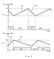
- Fig. 3(a) and (b) show a relation between a time-sequential variation of the voltage V32 of the condenser 34 and operation of the short circuit 32.
- Fig. 3 (a) is the case of a small primary current wherein inclination of a voltage rising line 71 is moderate while inclination of a voltage lowering line 72 is steep.
- Fig. 3 (b) shows the case of a large primary current wherein inclination of the voltage rising line 73 is steep while the inclination of the voltage lowering line 74 is moderate.
- ON or OFF indicates on or off state of the short circuit.
- a larger capacitance of the condenser 34 enables to make a period of ON/OFF longer.
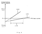
- Fig. 4 shows variation in voltage build-up rate at both terminals of the condenser 34 with respect to the value of the primary current.
- numeral 100 indicates a characteristic of the voltage build-up rate of the condenser 34 under the condition that the short circuit 32 is not operated.
- Numeral 101 indicates the rate under the condition that the short circuit 32 is operated.
- a value of current consumed at the controller, etc. is supposed to be constant.
- this power supply unit can operate within a range (indicated by numeral 110 in the drawing) in which the voltage build-up rate of the condenser 34 is plus (positive region) under the condition that the short circuit 32 is not operated at all (solid line 100 in the drawing), and the voltage build-up rate of the condenser 34 is minus (negative region) under the condition that the short circuit 32 is operated (solid line 101).
- the operable range 101 can be expressed as follows: ( Consumed current + R ⁇ 1 bypass current ) > transformer output current > consumed current
- the power supply unit is operable with this range 101.
- a rating of the output current from the current transformer 1 is elevated.
- a maximum limit of the primary current also comes to be lower. Therefore, it is essential to select a value of the rating capable of appropriately covering an operating range.
- Fig. 5 shows an arrangement of the power supply unit according to a first embodiment of the invention.
- the short circuit 32 is provided with short-circuits in parallel forming a parallel short circuit 32a (switching circuits connected in parallel) shown in Fig. 5. Further in order to cause each of the parallel short circuits 32a to sequentially operate as the primary current elevates, a plurality of voltage watching circuits 35 are provided and their values of the voltage V32 for outputting a command signal are made different respectively. As a result, coverage can be enlarged.
- Fig. 5 there are differences from the embodiment of Fig. 2 in the aspect that the parallel short circuits 32a are utilized and that a plurality of the voltage watching circuits 35a as many as the parallel short circuits 32a and different in voltage for actuation from each other, are utilized.
- Fig. 6 shows change in voltage build-up rate at both terminals of the condenser 34 with respect to a value of the primary current.
- numeral 100 indicates a characteristic of the voltage build-up rate of the condenser 34 when the short circuit is not operated at all.
- Numeral 101 shows the characteristic when one of the short circuits is operated.
- Numeral 102 shows the characteristic when two short circuits are operated, and
- numeral 103 shows the characteristic when three short circuits are operated.
- a value of current consumed at the controller, etc. is supposed to be constant.
- the primary current of this power supply unit can operate within a range (indicated by numeral 100 in the drawing) in which the voltage build-up rate of the condenser 34 is plus (positive region) under the condition that the parallel short circuit 32a is not operated at all (solid line 100 in the drawing), and the voltage build-up rate of the condenser 34 is minus (negative region indicated by 110 in the drawing) under the condition that the short circuit 32 is operated (solid line 101, 102, 103).
- Fig. 7 shows another preferred embodiment according to the invention.
- enlargement of a range of the primary current capable of obtaining an appropriate output voltage is achieved by arranging the resistances R1 to R3 of the short circuits in parallel.
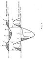
- a current transformer 1 is arranged so that material and configuration of a core thereof possesses a hysteresis characteristic of a strong tendency to be saturated (saturable reactor in the invention). Accordingly, when the primary current is small, like a region A indicated in Fig. 7 (a), an output from the current transformer is obtained in most regions of the power supply cycle. Meanwhile, as the primary current becomes larger, a magnetic characteristic of the current transformer 1 enters a saturated region at an initial point of each cycle. Thus, a region B where there is substantially no power supply to the condenser 34 increases and then the secondary output current does not substantially increase, thereby making it possible to prevent over voltage in the range of large primary current.
- An advantage of using the current transformer possessing characteristics shown in Fig. 7 is such that even if a power supply is obtained from any electrical equipment such as electric motor having a great range of variation in current value, a stable voltage can be obtained with respect to the wide range of variation in current value.
- Fig. 8 discloses a further novel feature relating to a non-contact power supply unit.
- the rectifier circuit is comprised of a rectifier circuit capable of obtaining a high voltage such as voltage-multiplying rectifier 31a, voltage-triplying rectifier or Cockcroft-Walton type rectifier. Any of these rectifier circuits are well known and therefore detailed description thereof is omitted.
- numeral 31a indicates the case of employing a voltage-multiplying rectifier. Parts other than the rectifier circuit are of the same arrangement as those in Fig. 2.
- the range of the primary current of the electric motor capable of obtaining a target voltage can be expanded to a range of smaller current.
Landscapes
- Engineering & Computer Science (AREA)
- Power Engineering (AREA)
- Rectifiers (AREA)
- Dc-Dc Converters (AREA)
- Power Conversion In General (AREA)
- Control Of Voltage And Current In General (AREA)
Description
- The present invention relates to a power supply unit that supplies a power to a measuring instrument for measuring various data of plant equipment or a watching device at the site where various plants are installed.
- In large-scale plant using a number of electrical equipment such as electric motor or transformer, various plant facilities such as power plant or water treatment plant, and the like, it is essential to secure reliability of the plant and improve a rate of operation. That is, in such a large-scale plant, data of the set-up electrical equipment is collected to serve as information concerning the operation, and operating conditions are subject to watching so as to be able to immediately cope with anything abnormal that has been detected.
- For such purposes, it is a recent trend to introduce an equipment condition-watching device for watching the conditions of the equipment so that various data are measured from the electric-power equipment, electrical equipment and the like installed in the plant. The data are then observed, and conditions of the equipment are watched or analyzed on the basis of the contents thereof.
- The equipment condition watching device for watching the conditions of the equipment is directed not only to machine/electrical equipment such as electric motor, electric generator, pump, valve and piping but also to calculator, printed board built in the equipment and measuring instrument.
- There have been conventionally two types of such equipment condition watching devices for watching the conditions of the equipment. One is a device that is located close to the electrical equipment to be watched. This device measures data of the equipment to be watched regularly or at arbitrary times, thereby watching the conditions of the equipment at the time of measurement in substitution for a patrol carried out by an operator in the plant (the device is hereinafter referred to as a detecting device). The other is a device that measures data of the equipment to be watched on line at all times via a plurality of the detecting devices, thereby watching the conditions at all times (the device is hereinafter referred to as a central control device). The detecting device and the central control device are both located, e.g., on the site of the same plant. However, several detecting devices are widely placed in a scattered manner in the so-called site, while the central control device is located in a centralized manner in the so-called control building or the like. Both of them are located within a relatively short distance from each other. As a result, in order to transmit the collected data, a method of transmission without construction of a power line such as radio system can be easily employed.
- Now, in order to operate the detecting device, a power supply is necessary as a matter of course. However, most of the detecting devices usually belong to a category of so-called light electric appliance and are operated at an extremely low voltage and a very small current. On the other hand, there are a lot of electrical equipment to be watched which can be operated at a high voltage and a large current. Therefore, it is often the case that although the device to be watched is an electrical equipment, an appropriate power supply for the detecting device is not available at the site of installation.
- As a matter of course, it may be said possible to obtain a low voltage from the electrical equipment to be watched by a well-known method such as using a pressure-reducing resistance or transformer. Actually, however, for the purpose of securing voltage endurance, cost effectiveness is exceedingly bad, and moreover it is difficult to prevent invasion of surge voltage resulting in deficiency in practical use. Thus, to provide a power supply, it becomes necessary to lay a power supply cable additionally as a power supply for measurement, or to employ a battery; otherwise an electric power must be generated at the site utilizing, e.g., a solar battery. However, in order to lay and connect the power supply cable to the detecting devices widely scattered in the plant, a large amount of cost and expenses are required. Moreover, the battery may bring about the trouble of maintenance or replacement. As for the solar battery, battery life is restricted, and a place for installation is so restricted that the solar battery cannot be used in this field of art.
- As a method to solve these problems, the Japanese Patent Publication (unexamined) No. 58960/1994 proposed a power supply unit.
- Fig. 9 is a schematic diagram of a known power supply unit which is similar to that disclosed in the above-mentioned gazette and which obtains a power via a current transformer used as a power supply for watching a transmission line. Fig. 10 is specific diagram of such a circuit. In Fig. 9, reference symbol A designates a power supply unit.
Reference numeral 81 designates a power line such as a distribution line. Numeral 82 designates a current transformer taking a power supply power from thepower line 81 in a non-contact manner.Numeral 83 designates an AC current control circuit.Numeral 84 designates a rectifier circuit.Numeral 85 designates a voltage detection/control circuit. - The power taken from the
current transformer 82 needs to be supplied as a stable power supply. This power control means is comprised of the ACcurrent control circuit 83, therectifier circuit 84 and the voltage detection/control circuit 85 in Fig. 9, and a circuitry thereof is specifically shown in Fig. 11. In the drawing, aresistance 86 in the ACcurrent control circuit 83 and a condenser 87 form a protective circuit for protection when an abnormal voltage such as surge is generated.Numeral 88 designates a triac. Numerals 89a, 89b are phototransistors. Therectifier circuit 84 is a full-wave rectifier circuit, and an output thereof is connected to circuits such asconstant voltage diode 90 and light-emitting diodes control circuit 85. Thus, when a DC output from therectifier circuit 84 exceeds an inverse voltage of theconstant voltage diode 90, a current flows through the light-emitting diodes triac 88. By this current, an anode and a cathode are brought into short circuit causing an input of AC to be interrupted. However, thetriac 88 will be recovered by means of zero cross point of AC and will supply power up to a next over voltage. - The conventional power supply unit is arranged as mentioned above so as to control Ac. Therefore, even if the primary current varies, any over voltage is not outputted. However, the voltage detection/
control circuit 85 operates at the moment when a value of a voltage waveform reaches to a voltage V90 of theconstant voltage diode 90, and theAC control circuit 83 operates so as to surpass the output voltage. Therefore, as shown in Fig. 11, as to the output waveform, duration of the waveform becomes smaller as the primary current augments. As a result, as shown in Fig. 12, an average value of the output voltage shows such a characteristic as to be lowered as the primary current augments, above a level of the operation of the triac. In Fig. 11,numeral 93 is a waveform of the output voltage of thetransformer 82 when the primary current is small.Numeral 94 is a waveform of the output voltage of thetransformer 82 when the primary current is large. Numeral 93a is a waveform of the output voltage after operating thetriac 88 on thewaveform 93 thereby interrupting the waveform. Numeral 94a is a waveform of the output voltage after operating thetriac 88 on thewaveform 94 thereby interrupting the waveform. - Therefore, a range of the primary current magnitude sufficient for obtaining a stable voltage output is narrow. Even if employing a circuit for stabilizing voltage as post-treatment, the voltage cannot be perfectly restrained from being fluctuated, After all, a performance as a power supply of an instrumentation circuit for carrying out a precise measurement is not sufficiently exhibited, and moreover, such a conventional power supply unit cannot be used for any power line subject to a load such as electric motor of which current value fluctuates largely.
- In the conventional power supply unit of above -mentioned arrangement, although the cable laying is not required, a problem exists in that a range of the primary current in which a stable output voltage can be obtained is exceedingly narrow, and moreover, another problem exists in that it is difficult to obtain a stable voltage as a power supply for instrumentation.
-
EP 0 421 204 A2 describes an overcurrent protection apparatus comprising a current transformer detecting an alternating current in an electric line, wherein the output of the transformer is rectified and a switching means and a resistor are connected in series across the output terminals of a rectifier. A control circuit comprises a capacitor, a comparator and a reference voltage generator, which is coupled in parallel with the switching means through a diode. - US 4,698,740 discloses a current fed regulated voltage supply, which is designed to provide a regulated DC power output from an AC current source. The power supply comprises a rectifier, an electronically controlled switch element with a shunt switch and a comparator whose output actuates the shunt switch.
- US 5,475,371 describes a faulted circuit detector having an isolated indicator detecting fault currents in a monitored conductor. When a fault of a predetermined magnitude is detected, a light pulse is transmitted from the detector to the indicator via a fiber optic cable, where, upon receipt, the pulse is converted to an electrical pulse, causing the indicator to indicate a fault state.
- The present invention was made to solve the above-discussed problems and has an object of providing a power supply unit that operates stably over wide range of variation in primary current and has a stability of such a level as to be capable of driving a computer at the site, as a power supply of a precise measuring instrument even in the case that the source of the primary current varies over a wide range, for example, in case of an electric motor.
- This object is achieved by a power supply unit having the features of
claim 1. - A power supply unit according to one example comprises:
- a current transformer mounted on a power supply line of an electrical equipment;
- a rectifier circuit connected to an output side of the mentioned current transformer;
- a condenser connected via a reverse current inhibit element to an output terminal of the mentioned rectifier circuit and charged with an output current from the mentioned current transformer;
- a plurality of voltage watching circuits for outputting command signals when the voltage at the two terminals of the mentioned condenser is exceeding voltage thresholds related to each of the voltage watching circuits and being different from one another and for stopping the plurality of command signals when the voltage across the condenser falls below each of the threshold voltages; and
- a plurality of switching circuit each connecting a resistor to the output terminal of the mentioned rectifier circuit in response to the mentioned command signal, and reducing a current for charging the mentioned condenser.
- As a result, a voltage can be taken from the power supply line in a non-contact manner, and also a stable voltage can be taken with respect to a wide range of variation in the primary current.
- A power supply unit may further comprise a constant voltage regulator for obtaining a predetermined constant voltage output from the voltage at both terminals of the mentioned condenser.
- As a result, an extremely stable voltage can be outputted over a very wide range of variation in the primary current.
- In the power supply unit according to the invention, it is preferable that the mentioned current transformer is a current transformer including a core surrounding the mentioned power supply line and a secondary winding wound around the mentioned core.
- As a result, a power supply can be taken in a non-contact manner.
- In the power supply unit according to the invention, it is preferable that the mentioned core is composed of a saturable reactor being magnetic-saturated in one cycle of a primary current of the mentioned current transformer.
- As a result , a stable output voltage can be obtained in the wider range of variation in the primary current.
- The power supply unit according to the invention further comprises a resistor connected in parallel with a secondary winding of the mentioned current transformer; and wherein the mentioned rectifier circuit is a voltage multiplying rectifier or Cockcroft-Walton type step up circuit.
- As a result , a stable output voltage can be obtained even in the range of low primary current.
- As a result , a stable constant voltage output can be obtained.
-
- Fig. 1 is a diagram for explaining an operating condition of a power supply unit in a plant according to the present invention.
- Fig. 2 is a circuit diagram of the power supply unit not falling under the claim.
- Figs. 3 (a) and (b) are waveform charts each for explaining an operation of the circuit in Fig. 2.
- Fig. 4 is a characteristic chart for explaining an operating characteristic of the circuit in Fig. 2.
- Fig. 5 is a circuit diagram of a power supply unit according to a first embodiment.
- Fig. 6 is a characteristic chart for explaining an operation of Fig. 5.
- Fig. 7 is a waveform chart explaining a characteristic of a current transformer in a power supply unit according to a second embodiment.
- Fig. 8 is a circuit diagram of a power supply unit not falling under the claim.
- Fig. 9 is a schematic diagram showing an arrangement of a conventional power supply unit.
- Fig. 10 is a circuit diagram of Fig. 9.
- Fig. 11 is a waveform chart for explaining an operation of Fig. 10.
- Fig. 12 is a characteristic chart for explaining a characteristic of the circuit in Fig. 10.
- Fig. 1 shows an arrangement of a detecting device electrically fed from a non-contact power supply unit according to a first preferred embodiment of the present invention together with arrangement of a central control device connected thereto. Fig. 2 shows a circuit of the non-contact
power supply unit 2 of Fig. 1. - In Fig. 1,
reference numerals central control device 12 installed in the control area of the same plant. Further, for the convenience of explanation,numerals 71designate radio waves 71 for providing a connection between the detectingdevices central control device 12. - As the detecting
devices device 11a will be hereinafter described. Shown in Fig. 1 are the detectingdevice 11a installed at not less than one site areas, and thecentral control device 12 installed in a control area apart from the site area by a certain distance, for example, several hundred meters. - In the site area, there is an
electric motor 21 fed via apower supply cable 30 from apower supply 28, and on thiselectric motor 21 or thepower supply cable 30, the detectingdevice 11a is mounted via acurrent transformer 1. - The detecting
device 11a includes: a plurality of detectors 22a1, 22a2, 22a3; a plurality of cables 32a1, 32a2, 32a3 for transmitting detected signals from these detectors; a plurality of signal converters 24a1, 24a2, 24a3 for converting the transmitted signals into digital signals capable of being processed in CPU; aCPU 25 for conducting a command of processing the signals; amemory 26 for storing the signals or commands; and aradio signal converter 33 for converting the signals into the signals in a communication format in order to transmit them to thecentral control device 12. - Furthermore, the signal converter 24a1, 24a2, 24a3, the
CPU 25 and thememory 26 are housed in acontroller 23. Thecontroller 23 is fed via thepower source cable 31 from thepower supply unit 2. When there are a plurality of the site areas, theother site area 11b is arranged in the same manner. - An operation of the non-contact power supply unit according to this embodiment not falling under the claim is hereinafter described with reference to Figs. 1, 2, 3 and 4.
- In the proximity of any device to be a watched such as the
electric motor 21 in Fig.1, thepower supply unit 2 for processing at site takes a secondary induced current to a coil 1a of thecurrent transformer 1 mounted on thepower supply cable 30 of the mentioned electric motor. The taken secondary induced current is rectified at therectifier circuit 31 to be converted into a DC low voltage and supplied to thecontroller 23, etc. - The
current transformer 1 is comprised of a current transformer coil 1a for outputting a secondary current and a guard element 1b for preventing that a high voltage is induced to a terminal of the current transformer coil 1a in the case of the terminal being erroneously opened. as long as the circuit for feeding the secondary induced current is normally connected, the guard element 1b is not operated and the secondary induced current is supplied to therectifier circuit 31. - The
rectifier circuit 31 having received the secondary induced current converts it into a DC voltage V31. However, when a value of the secondary induced current is larger than a total amount of current consumed in circuits disposed downstream (including not only the consumption in thecontroller 23 but also some amount of current consumed in each of the parts in the interior of the power supply unit 2), the secondary induced current passes through a reverse current inhibitelement 33 and stored as power in acondenser 34 to be a voltage source. At this time, a voltage V32 at both terminals of thecondenser 34 rises in such a rate as to satisfy the condition of being charged from a constant current source that outputs a current of (output current from the current transformer 1 - the mentioned consumed current). Then, after converted into target voltage at a constant voltage element 36 (i.e., a constant voltage regulator in the invention), the voltage V32 is smoothed at a smoothingcondenser 37 and supplied to thecontroller 32, etc. - The voltage V32 at both terminals of the
condenser 34 increases and decreases according to fluctuation in load current from thecontroller 23, etc. and fluctuation in output current from thecurrent transformer 1, i.e., increase and decrease in current from theelectric motor 21. Therefore, the voltage V32 of thecondenser 34 is detected at avoltage watching circuit 35. When the voltage V32 is charged up to an undesirably high voltage of being over an input endurance voltage (hereinafter referred to as V2) of theconstant voltage element 36, a command signal is outputted from thevoltage watching circuit 35 to cause a short circuit 32 (the switching circuit in the invention) to be in a conductive state. Thus, the output of therectifier circuit 31 is bypassed to a resistance R1 thereby an output voltage V31 of the rectifier being lowered. As a result, thecondenser 34 will not be charged and the voltage at both terminals V32 comes to be lowered corresponding to power consumption at the controller. - Under the operation of the
short circuit 32, the power at thecondenser 34 is inhibited by means of the reverse current inhibitelement 33, whereby there is no current flow back to theshort circuit 32. As a result of the controlled 23 continuing to operate under the action of theshort circuit 32, the power in thecondenser 34 is consumed, and the voltage V32 comes to drop. When the voltage V32 has dropped to a lower limit value (hereinafter referred to as V1) of the input voltage of theconstant voltage element 36, thevoltage watching circuit 35 resets the short-circuit state of theshort circuit 32 and starts again charging thecondenser 34. The operating voltage by which thevoltage watching circuit 35 outputs a command signal is hereinafter referred to as a first predetermined voltage. Further, the operating voltage for releasing the short-circuited state of theshort circuit 32 is hereinafter referred to as a second predetermined voltage. - For easy understanding, Fig. 3(a) and (b) show a relation between a time-sequential variation of the voltage V32 of the
condenser 34 and operation of theshort circuit 32. Fig. 3 (a) is the case of a small primary current wherein inclination of avoltage rising line 71 is moderate while inclination of avoltage lowering line 72 is steep. Fig. 3 (b) shows the case of a large primary current wherein inclination of thevoltage rising line 73 is steep while the inclination of thevoltage lowering line 74 is moderate. In the drawings, ON or OFF indicates on or off state of the short circuit. As a matter of course, a larger capacitance of thecondenser 34 enables to make a period of ON/OFF longer. - For easier understanding, Fig. 4 shows variation in voltage build-up rate at both terminals of the
condenser 34 with respect to the value of the primary current. In the drawing, numeral 100 indicates a characteristic of the voltage build-up rate of thecondenser 34 under the condition that theshort circuit 32 is not operated.Numeral 101 indicates the rate under the condition that theshort circuit 32 is operated. However, in Fig. 4, for convenience of explanation, a value of current consumed at the controller, etc. is supposed to be constant. Note that the primary current of this power supply unit can operate within a range (indicated by numeral 110 in the drawing) in which the voltage build-up rate of thecondenser 34 is plus (positive region) under the condition that theshort circuit 32 is not operated at all (solid line 100 in the drawing), and the voltage build-up rate of thecondenser 34 is minus (negative region) under the condition that theshort circuit 32 is operated (solid line 101). - In this power supply unit, when a value of the primary current of the
current transformer 1 becomes smaller and the voltage V32 of thecondenser 34 can not rise despite theshort circuit 32 being off, a predetermined voltage cannot be outputted in a short time, resulting in stop of the operation. Additionally, when the primary current becomes larger than predicted, rise of the voltage V32 cannot be stopped even if theshort circuit 32 is on. - The
operable range 101 can be expressed as follows:
range 101. - If the state in which the output current from the transformer exceeds (consumed current +
R 1 bypass current) may continue for a long time, the voltage at both terminals of thecondenser 34 will be increased to be extremely high. Therefore, to prevent this, a constant voltage diode Z is incorporated in theshort circuit 32 for the purpose of bypassing the current and apparently increasing the consumed current upon exceeding a limit voltage. - In order to make lower a minimum limit of the primary current in which the
constant voltage regulator 36 can output a predetermined voltage, it is preferable that a rating of the output current from thecurrent transformer 1 is elevated. However, note that, in such a case, a maximum limit of the primary current also comes to be lower. Therefore, it is essential to select a value of the rating capable of appropriately covering an operating range. - With such circuits, it is possible to secure a power supply for the detecting device, a measuring instrument or the like in the proximity of various electrical equipment facilities to be watched, thereby making it possible to reduce considerably an amount of laying the power supply cable.
- Furthermore, even in any electrical equipment such as electric motor of which current level largely varies and in which, at the time of starting, a large amount of current flows ranging from several to ten-odd times as large as that in a normal state, a stable constant voltage can be obtained.
- Fig. 5 shows an arrangement of the power supply unit according to a first embodiment of the invention.
- In the foregoing embodiment, a maximum value of the primary current is affected due to a current capacity of the element forming the
short circuit 32. Therefore, in order to further apply the circuit up to a region of large current, theshort circuit 32 is provided with short-circuits in parallel forming a parallelshort circuit 32a (switching circuits connected in parallel) shown in Fig. 5. Further in order to cause each of the parallelshort circuits 32a to sequentially operate as the primary current elevates, a plurality ofvoltage watching circuits 35 are provided and their values of the voltage V32 for outputting a command signal are made different respectively. As a result, coverage can be enlarged. - In Fig. 5, there are differences from the embodiment of Fig. 2 in the aspect that the parallel
short circuits 32a are utilized and that a plurality of thevoltage watching circuits 35a as many as the parallelshort circuits 32a and different in voltage for actuation from each other, are utilized. - Operation of the first embodiment is now described referring to the drawings. However, further description about the same parts as that of the foregoing embodiment is omitted.
- When the voltage of the
condenser 34 having stored a rectified power rises and comes to a predetermined voltage, one element of the parallelshort circuits 32a is short-circuited. The short circuit is established via a resistance R1 connected in series to the element. Thus, when the primary current further increases, the voltage V31 of therectifier circuit 31 increases and approaches again to an allowable maximum limit value of theconstant value element 36. In Fig. 5, before this, the other elements of the parallelshort circuits 32a are brought into conduction, and the voltage build-up rate of the voltages V31 and V32 is restrained by arranging resistances R1 and R2 in parallel. Further increase in number of the short circuits in parallel makes it possible to apply to a wider range of the primary current. In addition, it is necessary to set a resistance at the time of short circuit to be such that value of the parallel resistance during operation is not more than load impedance of the power supply. - For easy understanding, Fig. 6 shows change in voltage build-up rate at both terminals of the
condenser 34 with respect to a value of the primary current. In the drawing, numeral 100 indicates a characteristic of the voltage build-up rate of thecondenser 34 when the short circuit is not operated at all.Numeral 101 shows the characteristic when one of the short circuits is operated.Numeral 102 shows the characteristic when two short circuits are operated, and numeral 103 shows the characteristic when three short circuits are operated. However, in Fig. 6, for convenience of explanation, a value of current consumed at the controller, etc. is supposed to be constant. Note that the primary current of this power supply unit can operate within a range (indicated by numeral 100 in the drawing) in which the voltage build-up rate of thecondenser 34 is plus (positive region) under the condition that the parallelshort circuit 32a is not operated at all (solid line 100 in the drawing), and the voltage build-up rate of thecondenser 34 is minus (negative region indicated by 110 in the drawing) under the condition that theshort circuit 32 is operated (solid line - It is an advantage of this first embodiment that an applicable range of the primary current of electric motor or the like can be enlarged.
- Fig. 7 shows another preferred embodiment according to the invention.
- In the foregoing first embodiment, enlargement of a range of the primary current capable of obtaining an appropriate output voltage is achieved by arranging the resistances R1 to R3 of the short circuits in parallel. Alternatively, it is also preferable that reducing the output current itself from the
current transformer 1 as the primary current increases enlarges applicable range of the primary current. - Referring to Fig. 7, a
current transformer 1 is arranged so that material and configuration of a core thereof possesses a hysteresis characteristic of a strong tendency to be saturated (saturable reactor in the invention). Accordingly, when the primary current is small, like a region A indicated in Fig. 7 (a), an output from the current transformer is obtained in most regions of the power supply cycle. Meanwhile, as the primary current becomes larger, a magnetic characteristic of thecurrent transformer 1 enters a saturated region at an initial point of each cycle. Thus, a region B where there is substantially no power supply to thecondenser 34 increases and then the secondary output current does not substantially increase, thereby making it possible to prevent over voltage in the range of large primary current. - An advantage of using the current transformer possessing characteristics shown in Fig. 7 is such that even if a power supply is obtained from any electrical equipment such as electric motor having a great range of variation in current value, a stable voltage can be obtained with respect to the wide range of variation in current value.
- Fig. 8 discloses a further novel feature relating to a non-contact power supply unit.
- In actual plant, it is possible that an insulation breakdown accident may occur in the
current transformer 1 due to break on the secondary wiring of thecurrent transformer 1. Therefore, to prevent such a trouble, it is sometime desirable to connect a guard resistance 1C at an output terminal of the secondary winding as shown in Fig. 8. - In this case, in the full-
wave rectifier circuit 31 according to the foregoing embodiment shown in Fig. 2, when the primary current of the electric motor is small, the voltage V31 after rectification will be short. Considering a forward voltage drop in the reverse current inhibitelement 33, theconstant voltage element 36 is not supplied with a sufficient voltage, thereby making it impossible to obtain any constant target voltage. - To cope with such a problem, it is preferable that the rectifier circuit is comprised of a rectifier circuit capable of obtaining a high voltage such as voltage-multiplying
rectifier 31a, voltage-triplying rectifier or Cockcroft-Walton type rectifier. Any of these rectifier circuits are well known and therefore detailed description thereof is omitted. In Fig. 8, numeral 31a indicates the case of employing a voltage-multiplying rectifier. Parts other than the rectifier circuit are of the same arrangement as those in Fig. 2. - In the circuit of Fig. 8, the range of the primary current of the electric motor capable of obtaining a target voltage can be expanded to a range of smaller current.
Claims (1)
- A power supply unit comprising:a current transformer (1) mounted on a power supply line (30) of an electrical equipment (21);a rectifier circuit (31) connected to an output side of said current transformer (1);a condenser (34) connected via a reverse current inhibit element (33) to an output terminal of said rectifier circuit (31) and charged with an output current from said current transformer (1);a plurality of voltage watching circuits (35, 35a) for outputting at least one command signal when a voltage at both terminals of said condenser (34) is over a predetermined first voltage, and for stopping said command signal when said voltage at both terminals is below a predetermined second voltage; anda plurality of switching circuits (32, 32a) each having a resistor for connecting at least one resistor (R1, R2, R3) to the output terminal of said rectifier circuit (31) in response to said command signal, and reducing a current for charging said condenser (27), andwherein said first predetermined voltage set at each of said plurality of voltage watching circuits is different from each other.
Applications Claiming Priority (2)
| Application Number | Priority Date | Filing Date | Title |
|---|---|---|---|
| JP2001239876A JP2003050637A (en) | 2001-08-07 | 2001-08-07 | Power supply |
| JP2001239876 | 2001-08-07 |
Publications (4)
| Publication Number | Publication Date |
|---|---|
| EP1306965A2 EP1306965A2 (en) | 2003-05-02 |
| EP1306965A3 EP1306965A3 (en) | 2005-02-09 |
| EP1306965B1 EP1306965B1 (en) | 2006-09-20 |
| EP1306965B9 true EP1306965B9 (en) | 2007-02-21 |
Family
ID=19070569
Family Applications (1)
| Application Number | Title | Priority Date | Filing Date |
|---|---|---|---|
| EP02000203A Expired - Lifetime EP1306965B9 (en) | 2001-08-07 | 2002-01-10 | Power supply unit |
Country Status (4)
| Country | Link |
|---|---|
| US (1) | US6496391B1 (en) |
| EP (1) | EP1306965B9 (en) |
| JP (1) | JP2003050637A (en) |
| DE (1) | DE60214810T2 (en) |
Families Citing this family (23)
| Publication number | Priority date | Publication date | Assignee | Title |
|---|---|---|---|---|
| JP2006139755A (en) * | 2004-10-15 | 2006-06-01 | Toshiba Lighting & Technology Corp | LED type marker lamp lighting device and marker lamp system |
| JP4899950B2 (en) * | 2007-03-08 | 2012-03-21 | パナソニック電工株式会社 | 2-wire switch device |
| KR100943437B1 (en) | 2007-11-06 | 2010-02-19 | 한국전기연구원 | Non-contact power supply for high voltage distribution line and method |
| DE102008027583B4 (en) * | 2008-06-10 | 2010-11-18 | Siemens Aktiengesellschaft | Circuit for a power supply for generating a DC voltage |
| AU2010258254B2 (en) * | 2009-06-08 | 2014-05-01 | Instruform Pacific Limited | Power supply |
| WO2010145688A1 (en) | 2009-06-15 | 2010-12-23 | Areva T&D Uk Limited | Converter control |
| JP2012026735A (en) * | 2010-07-20 | 2012-02-09 | Fujitsu Ltd | Current detection apparatus |
| US8476859B2 (en) | 2010-09-30 | 2013-07-02 | Rockwell Automation Technologies, Inc. | DC power for SGCT devices using a high frequency current loop with multiple current transformers |
| US8461797B2 (en) * | 2011-01-28 | 2013-06-11 | I-Shou University | Current direction detection module |
| DE202011002880U1 (en) * | 2011-01-29 | 2012-05-02 | Aizo Ag | Semiconductor power supply |
| US8767071B1 (en) | 2011-03-03 | 2014-07-01 | The United States Of America As Represented By The Secretary Of The Air Force | High voltage power line multi-sensor system |
| US8437157B2 (en) | 2011-03-16 | 2013-05-07 | Marmon Utility, Llc | Power line current fed power supplies producing stable load currents and related methods |
| US9188610B1 (en) * | 2012-01-18 | 2015-11-17 | Thomas G. Edel | Apparatus for measuring multiple electric currents utilizing multiple current transformers |
| KR101383173B1 (en) | 2012-06-05 | 2014-04-09 | (주)파워닉스 | Drive power supply apparatus and method |
| CN104184345A (en) * | 2013-05-24 | 2014-12-03 | 海洋王(东莞)照明科技有限公司 | Conversion circuit and lighting device |
| CN104184346A (en) * | 2013-05-27 | 2014-12-03 | 海洋王(东莞)照明科技有限公司 | Conversion circuit |
| JP6286936B2 (en) * | 2013-08-22 | 2018-03-07 | 富士電機株式会社 | POWER CIRCUIT DEVICE, CURRENT MEASUREMENT DEVICE, POWER MONITORING SYSTEM, AND POWER CIRCUIT DEVICE PROTECTION METHOD |
| JP6500639B2 (en) * | 2015-01-29 | 2019-04-17 | 富士通株式会社 | POWER SUPPLY CONTROL CIRCUIT, ENVIRONMENTAL POWER GENERATING APPARATUS, AND CONTROL METHOD OF ECOGENIC POWER GENERATING APPARATUS |
| CN107656119B (en) * | 2017-10-23 | 2023-10-03 | 浙江大学 | Passive wireless current sensor device |
| US11139746B2 (en) * | 2019-01-31 | 2021-10-05 | Rockwell Automation Technologies, Inc. | Power converter with reduced switch mode power supply EMI |
| JP7257913B2 (en) * | 2019-08-02 | 2023-04-14 | 株式会社日立製作所 | Power supply device, power supply method, and railway vehicle monitoring system using the power supply device |
| KR102212166B1 (en) * | 2020-01-02 | 2021-02-05 | 주식회사 폰 | High output power supply easily installed in underground transmission line with improved waterproof/dustproof function |
| EP4786411A2 (en) | 2023-06-20 | 2026-08-05 | Alice & Bob | Method of measuring an observable of a cat qubit |
Family Cites Families (17)
| Publication number | Priority date | Publication date | Assignee | Title |
|---|---|---|---|---|
| US3641421A (en) * | 1971-02-24 | 1972-02-08 | Gen Electric | Commutation control for inverter circuits |
| US3742302A (en) * | 1971-10-12 | 1973-06-26 | Carrier Corp | Motor relay protection for refrigerant compressor motors |
| US4383293A (en) * | 1981-11-16 | 1983-05-10 | Acme Electric Corporation | Isolated DC current sense circuit |
| US4698740A (en) * | 1986-02-14 | 1987-10-06 | Westinghouse Electric Corp. | Current fed regulated voltage supply |
| US4974141A (en) * | 1988-05-18 | 1990-11-27 | Viteq Corporation | AC to DC power converter with input current waveform control for buck-boost regualtion of output |
| US4964029A (en) * | 1988-05-18 | 1990-10-16 | Viteq Corporation | AC to DC power converter with input current waveform control for buck-boost regulation of output |
| JPH0710145B2 (en) * | 1989-10-04 | 1995-02-01 | 三菱電機株式会社 | Overcurrent protection device |
| US5475371A (en) * | 1990-06-25 | 1995-12-12 | Cooper Industries, Inc. | Faulted circuit detector having isolated indicator |
| US5337205A (en) * | 1990-07-24 | 1994-08-09 | Square D Company | Dual voltage power supply |
| WO1992022955A1 (en) * | 1991-06-19 | 1992-12-23 | Ant Nachrichtentechnik Gmbh | Switching regulator |
| GB2261533A (en) * | 1991-10-14 | 1993-05-19 | Astec Int Ltd | Indirect inductor current measurements in SMPS |
| JPH0658960A (en) | 1992-08-04 | 1994-03-04 | Central Res Inst Of Electric Power Ind | Power line measuring device |
| FR2706699B1 (en) * | 1993-06-10 | 1995-09-15 | Gec Alsthom T & D Sa | Device for supplying a voltage to an electronic circuit, in particular to an electronic circuit associated with an intensity sensor placed on an electric line. |
| US5521488A (en) * | 1994-01-10 | 1996-05-28 | Motorola, Inc. | Voltage regulator and method therefor |
| KR0154818B1 (en) * | 1995-12-28 | 1998-12-15 | 김광호 | Resonant Converter Control System |
| US5982136A (en) * | 1996-01-18 | 1999-11-09 | International Rectifier Corporation | Circuit for sensing current in power trains for motor control |
| US6320772B1 (en) * | 1999-05-26 | 2001-11-20 | Matsushita Electric Industrial Co., Ltd. | Converter circuit having control means with capability to short-circuit converter output |
-
2001
- 2001-08-07 JP JP2001239876A patent/JP2003050637A/en active Pending
-
2002
- 2002-01-10 EP EP02000203A patent/EP1306965B9/en not_active Expired - Lifetime
- 2002-01-10 DE DE60214810T patent/DE60214810T2/en not_active Expired - Fee Related
- 2002-01-15 US US10/045,032 patent/US6496391B1/en not_active Expired - Fee Related
Also Published As
| Publication number | Publication date |
|---|---|
| EP1306965A2 (en) | 2003-05-02 |
| JP2003050637A (en) | 2003-02-21 |
| DE60214810D1 (en) | 2006-11-02 |
| EP1306965A3 (en) | 2005-02-09 |
| DE60214810T2 (en) | 2007-09-20 |
| US6496391B1 (en) | 2002-12-17 |
| EP1306965B1 (en) | 2006-09-20 |
Similar Documents
| Publication | Publication Date | Title |
|---|---|---|
| EP1306965B1 (en) | Power supply unit | |
| US9257829B2 (en) | Grounding apparatus | |
| EP3414812B1 (en) | Apparatus, system and method for power extraction | |
| EP0267595A1 (en) | Power supply magnetic shunt for transmission line sensor module | |
| JP6907967B2 (en) | Arc discharge detector | |
| KR102617970B1 (en) | System for protection management of lvds distribution and method for protection management | |
| US8519572B2 (en) | Self power-acquiring quick-responsive controllable reactor | |
| EP0118779A1 (en) | Voltage regulator for charging generator | |
| US11356012B2 (en) | Transmission and distribution system with electric shock protection function and method of operating the same | |
| US20250341877A1 (en) | Automatic circuit allocation of remote devices in a multi-power supply system | |
| US11038336B1 (en) | Redundant power module and discharge circuit for improved substation device availability | |
| KR20120086558A (en) | Solar power generation system with monitoring and neutral line replacement | |
| US4516198A (en) | Control system for DC power transmission | |
| US8755160B2 (en) | Measuring transient electrical activity in aircraft power distribution systems | |
| KR102705174B1 (en) | Electric source surge protective apparatus using transformer and surge monitoring system using the same | |
| JP5026179B2 (en) | Cable fault point measuring instrument | |
| JP2020180787A (en) | Detection device and power supply | |
| EP2328246A1 (en) | Electricity distribution system and method for adapting a TT electricity distribution network | |
| US11740265B1 (en) | Signal conditioning circuit | |
| CN111786373B (en) | Arc suppression coil control system | |
| CN221174889U (en) | Indicating circuit of charge control circuit breaker and charge control circuit breaker | |
| JP2020004795A (en) | Monitoring system and monitoring device for stationary induction machine | |
| CN117748409A (en) | DC blocking device for neutral point of transformer and control method thereof | |
| JPH0444492B2 (en) | ||
| CN118282045A (en) | Voltage parallel cabinet for switch station of pumped storage power station |
Legal Events
| Date | Code | Title | Description |
|---|---|---|---|
| PUAI | Public reference made under article 153(3) epc to a published international application that has entered the european phase |
Free format text: ORIGINAL CODE: 0009012 |
|
| AK | Designated contracting states |
Designated state(s): AT BE CH CY DE DK ES FI FR GB GR IE IT LI LU MC NL PT SE TR |
|
| AX | Request for extension of the european patent |
Extension state: AL LT LV MK RO SI |
|
| PUAL | Search report despatched |
Free format text: ORIGINAL CODE: 0009013 |
|
| AK | Designated contracting states |
Kind code of ref document: A3 Designated state(s): AT BE CH CY DE DK ES FI FR GB GR IE IT LI LU MC NL PT SE TR |
|
| AX | Request for extension of the european patent |
Extension state: AL LT LV MK RO SI |
|
| 17P | Request for examination filed |
Effective date: 20050512 |
|
| AKX | Designation fees paid |
Designated state(s): DE FR |
|
| GRAP | Despatch of communication of intention to grant a patent |
Free format text: ORIGINAL CODE: EPIDOSNIGR1 |
|
| RAP1 | Party data changed (applicant data changed or rights of an application transferred) |
Owner name: MITSUBISHI DENKI KABUSHIKI KAISHA |
|
| GRAS | Grant fee paid |
Free format text: ORIGINAL CODE: EPIDOSNIGR3 |
|
| GRAA | (expected) grant |
Free format text: ORIGINAL CODE: 0009210 |
|
| AK | Designated contracting states |
Kind code of ref document: B1 Designated state(s): DE FR |
|
| RIN2 | Information on inventor provided after grant (corrected) |
Inventor name: HATTORI, TAKAYUKI Inventor name: IKEDA, IKUO |
|
| REF | Corresponds to: |
Ref document number: 60214810 Country of ref document: DE Date of ref document: 20061102 Kind code of ref document: P |
|
| PGFP | Annual fee paid to national office [announced via postgrant information from national office to epo] |
Ref country code: DE Payment date: 20070125 Year of fee payment: 6 |
|
| ET | Fr: translation filed | ||
| PLBE | No opposition filed within time limit |
Free format text: ORIGINAL CODE: 0009261 |
|
| STAA | Information on the status of an ep patent application or granted ep patent |
Free format text: STATUS: NO OPPOSITION FILED WITHIN TIME LIMIT |
|
| 26N | No opposition filed |
Effective date: 20070621 |
|
| PGFP | Annual fee paid to national office [announced via postgrant information from national office to epo] |
Ref country code: FR Payment date: 20070126 Year of fee payment: 6 |
|
| PG25 | Lapsed in a contracting state [announced via postgrant information from national office to epo] |
Ref country code: DE Free format text: LAPSE BECAUSE OF NON-PAYMENT OF DUE FEES Effective date: 20080801 |
|
| REG | Reference to a national code |
Ref country code: FR Ref legal event code: ST Effective date: 20081029 |
|
| PG25 | Lapsed in a contracting state [announced via postgrant information from national office to epo] |
Ref country code: FR Free format text: LAPSE BECAUSE OF NON-PAYMENT OF DUE FEES Effective date: 20080131 |