EP1306962A1 - Small power generating device and water faucet device - Google Patents
Small power generating device and water faucet device Download PDFInfo
- Publication number
- EP1306962A1 EP1306962A1 EP01930184A EP01930184A EP1306962A1 EP 1306962 A1 EP1306962 A1 EP 1306962A1 EP 01930184 A EP01930184 A EP 01930184A EP 01930184 A EP01930184 A EP 01930184A EP 1306962 A1 EP1306962 A1 EP 1306962A1
- Authority
- EP
- European Patent Office
- Prior art keywords
- fluid
- hydraulic turbine
- flow
- rotor
- small generator
- Prior art date
- Legal status (The legal status is an assumption and is not a legal conclusion. Google has not performed a legal analysis and makes no representation as to the accuracy of the status listed.)
- Granted
Links
Images


Classifications
-
- H—ELECTRICITY
- H02—GENERATION; CONVERSION OR DISTRIBUTION OF ELECTRIC POWER
- H02K—DYNAMO-ELECTRIC MACHINES
- H02K5/00—Casings; Enclosures; Supports
- H02K5/04—Casings or enclosures characterised by the shape, form or construction thereof
- H02K5/12—Casings or enclosures characterised by the shape, form or construction thereof specially adapted for operating in liquid or gas
- H02K5/128—Casings or enclosures characterised by the shape, form or construction thereof specially adapted for operating in liquid or gas using air-gap sleeves or air-gap discs
-
- F—MECHANICAL ENGINEERING; LIGHTING; HEATING; WEAPONS; BLASTING
- F03—MACHINES OR ENGINES FOR LIQUIDS; WIND, SPRING, OR WEIGHT MOTORS; PRODUCING MECHANICAL POWER OR A REACTIVE PROPULSIVE THRUST, NOT OTHERWISE PROVIDED FOR
- F03B—MACHINES OR ENGINES FOR LIQUIDS
- F03B13/00—Adaptations of machines or engines for special use; Combinations of machines or engines with driving or driven apparatus; Power stations or aggregates
-
- H—ELECTRICITY
- H02—GENERATION; CONVERSION OR DISTRIBUTION OF ELECTRIC POWER
- H02K—DYNAMO-ELECTRIC MACHINES
- H02K7/00—Arrangements for handling mechanical energy structurally associated with dynamo-electric machines, e.g. structural association with mechanical driving motors or auxiliary dynamo-electric machines
- H02K7/18—Structural association of electric generators with mechanical driving motors, e.g. with turbines
- H02K7/1807—Rotary generators
- H02K7/1823—Rotary generators structurally associated with turbines or similar engines
Definitions
- the present invention relates to a small generator utilizing a hydroelectric generated by a water flow passing through a faucet and a Water tap apparatus contains a small generator is provided.
- a hydraulic turbine is provided in a fluid path to be a water flowing path and rotates by receiving the hydroelectric of flowing water.
- a rotor is fixed integrally with the rotary shaft of the hydraulic turbine.
- the outer peripheral surface of the rotor is a magnetized as a rotor magnet.
- the rotor magnet is opposed to a stator pole through the wall of a non-magnetic member.
- single layer stator coil is provided to be interlinked with a magnetic flux passing through the stator pole.
- the hydraulic turbine rotates by receiving the hydroelectric of the flowing water so that a magnet rotates relatively with respect to the stator pole. Therefore, the flow of the magnetic flux flowing to the rotor and the stator pole is changed.
- a current flows to the stator coil in such a direction as to prevent the change in the flow of the magnetic flux. After the current is rectified, it is stored in a storage battery.
- the magnetic flux flows between the rotor and the stator pole in the generator.
- the magnetic flux acts as a resistance when the hydraulic turbine is to be rotated by the hydroelectric caused by flowing the water.
- a magnetic flux generated between the rotor and the stator pole acts as a detent torque to brake the operation of the hydraulic turbine during the starting and rotation of the hydraulic turbine. Accordingly, in order to rotate the hydraulic turbine, it should receive a flow amount and a hydraulic pressure beyond a predetermined value. Therefore, if the flow amount is small or the hydraulic pressure of the flowing water received by the hydraulic turbine is low, the hydraulic turbine is neither rotated nor generates a power. If the magnetic force of the rotor magnet is low, the detent torque is reduced so that the hydraulic turbine itself is rotated.
- a small generator comprising a hydraulic turbine, provided in a fluid path, rotating by passing a fluid in a predetermined flow rate, a rotator, coupled to the hydraulic turbine, rotating together with the hydraulic turbine, the rotator acting as a rotor portion opposed to a stator portion having multiple layers in a stepping motor including the stator portion, wherein the rotor portion rotates relatively with respect to the stator portion by with passing the fluid to generate a power.
- the stator portion of the stepping motor for power generation is constituted by multiple of layers. Therefore, each layer acts to cancel a detent torque between the stator portion and the rotor so that the detent torque can be reduced.
- the hydraulic turbine can rotate with a small flow at a low hydraulic pressure.
- a detent torque generated between the stator portion and the rotor is set to be cancelled by the layers each other.
- the detent torque is positively set to be reduced by skewing each layer (rotating the layer in a circumferential direction to intentionally shift a pole thereof) or providing a non-magnetic member between the layers. Consequently, the functions can be obtained more effectively.
- an injecting member including an injecting hole which acts as a part of the fluid path and acts to throttle a flow for a passage to inject a fluid onto a blade portion of the hydraulic turbine. Consequently, it is possible to raise a hydraulic pressure to some extent through the injecting hole even if the flow is small. Therefore, it is possible to rotate the hydraulic turbine more smoothly, thereby generating a power.
- each of the small generators can generate a power with a small flow at a low pressure by reducing the detent torque. Therefore, it is also possible to generate a power without greatly raising the hydraulic pressure through an increase in the diameter of the injecting hole. In the case in which such setting is carried out, it is possible to reduce a possibility that the injecting member might be damaged due to a high hydraulic pressure.
- a Water Tap apparatus wherein a valve opening degree is controlled to include at least two modes of a water saving mode in which a flow of a fluid to flow to a fluid path and a normal mode for a normal flow and the small generator of the present invention described in claims 6 to 9 is provided in the fluid path.
- the detent torque is reduced in the small generator according to the present invention described in claims 6 to 9 which is provided in the fluid path. Therefore, it is possible to generate a power with a small flow at a low hydraulic pressure. Therefore, if the hydraulic pressure of the fluid to be supplied to the hydraulic turbine is set to be low, it is possible to reduce a possibility that the member might be damaged due to a high hydraulic pressure in the normal mode and to sufficiently generate a power also in the water saving mode.
- the flow in the water saving mode is set to 2.0 liters/minute to 3.0 liters/minute. Therefore, the water saving can fully be carried out and the power can be generated in a small amount of water.
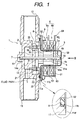
- Fig. 1 is a longitudinal sectional view showing a small generator of a two-layer stepping motor type according to the first embodiment of the invention.
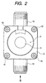
- Fig. 2 is a side view showing the small generator of Fig. 1 taken along an arrow II in Fig. 1.
- Fig. 3 is a bottom view showing the state of Fig. 2 taken along an arrow III.
- Fig. 4 is a typical view showing a relationship between a member (nozzle ring) for spraying a fluid onto a hydraulic turbine in a state in which a hydraulic pressure is raised by throttling a fluid path and the hydraulic turbine.
- the small generator utilizing a two-layer stepping motor type comprises a casing 1, a nozzle ring 2 provided in the casing 1, a hydraulic turbine 3 rotatably provided on the inner peripheral side of the nozzle ring 2, a rotor 4 rotating integrally with the hydraulic turbine 3, a cup-shaped member 5 formed of stainless which is provided on the outer peripheral side of the rotor 4, and a stator portion 6 of a stepping motor which is further provided on the outside of the cup-shaped member 5.
- the casing 1 includes a body portion 11, and an inlet path 12 and an outlet path 13 which are protruded toward the outside of the body portion 11.
- the body portion 11 has a generation part attaching portion 11a for attaching a generation part constituted by the rotor 4 and the stator portion 6.
- the generation part attaching portion 11a is constituted by an open end face portion formed on the right side of the bodyportion 11 in Fig. I and an outer peripheral portion thereof, and a circumferential groove 11b is formed in the outer peripheral portion.
- An O ring 8 is embedded in the groove 11b.
- a flange portion 52 of the cup-shaped member 5 is pushed to seal the O ring 8 in the groove 11b and a cover member 9 is provided to interpose the flange portion 52 of the cup-shaped member 5 together with the generation part attaching portion 11a in a state in which the outer peripheral end of the flange portion 52 is caused to abut on a convex portion 11d formed in the body portion 11 (see the enlarged view of Fig. 1). More specifically, the cup-shaped member 5 is pushed against the generation part attaching portion 11a while crushing the O ring 8 in the groove 11b, and furthermore, the cover member 9 covers from above.
- the cup-shaped member 5 When the outer peripheral end of the flange portion 52 of the cup-shaped member 5 is thus caused to abut on the inner peripheral part of the convex portion 11d, the cup-shaped member 5 is positioned in the inner peripheral part of the stator portion 6. As shown in Fig. 2, four screws 10 are inserted in screw holes formed on four corners of the cover member 9 for screwing so that the cover portion 9 is fixed to the body portion 11 of the casing 1. Consequently, the generation part attaching portion 11a to be the open end face of the casing 1 is closed by the cup-shaped member 5.
- the cup-shaped member 5 is formed of a non-magnetic stainless member, and has the flange portion 52, a cylindrical portion 51 and a bottom portion 53 formed through throttling.
- a bearing 15 for rotatably receiving one of ends of a shaft 7 supporting the hydraulic turbine 3 and the rotor 4 is fitted in the bottom portion 53.
- the cup-shaped member 5 serves to separate the stator portion 6 of the stepping motor from a fluid passing through the inside of the casing 1 and to prevent the fluid from flowing out of the casing 1.
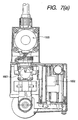
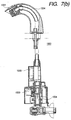
- the inlet path 12 and the outlet path 13 which are formed in the casing 1 and a coupling path 14 for coupling them are provided in a part of a fluid path of a Water Tap apparatus (as shown in Fig. 7) constituted by a faucet, a valve and the like, and a fluid entering the inlet path 12 from a fluid source passes through the coupling path 14 and is then discharged from the outlet path 13.
- the fluid serves to give the rotating force to the hydraulic turbine 3 during the passage. This portion will be described below in detail.
- the other end of the shaft 7 supporting the rotation of the hydraulic turbine 3 and the rotor 4 which will be described below is rotatably provided in the coupling path 14.
- One of ends of the shaft 7 is rotatably fitted in a hole 14a for a bearing which is formed in the coupling path 14 of the casing 1 and the other end side thereof is rotatably fitted in the bearing 15 having a tip provided in the cup-shaped member 5 through the open end face. Consequently, the shaft 7 is held by cooperate the casing 1 with the cup-shaped member 5.
- the nozzle ring 2 to be an injecting member acting as a part of the fluid path of the Water Tap apparatus and serving to throttle the flow of the passing fluid and to inject the fluid to a blade portion 31 (see Fig. 4) of the hydraulic turbine 3 is fitted in the coupling path 14 of the casing 1 by pressure.
- the nozzle ring 2 has an cylindrical ring portion 21 and a flange portion 22 formed by bending one of open ends of the ring portion 21 in a peripheral direction.
- Two nozzles 23 are provided in symmetrical positions by approximately 180 degrees in the ring portion 21 as shown in Fig. 4 in such a manner that the two nozzles 23 serve as injecting holes for throttling an inlet passage of the fluid entering the inlet path 12 and for injecting the fluid to the blade portion 31 of the hydraulic turbine 3 disposed on the inside.
- the hydraulic turbine 3 provided in the nozzle ring 2 to be a part of the fluid path, rotates with the passage of the fluid in a predetermined flow.
- the hydraulic turbine 3 includes a cylindrical ring portion 32 and the blade portion 31 having an outer peripheral tip portion connected to one of side end faces of the ring portion 32 and a central portion inserted and fixed to the shaft 7.
- the blade portion 31 is curved circularly to easily receive the pressure of the fluid from the nozzle 23. For this reason, the fluid which enters the inlet path 12 and is then throttled with the two nozzles 23 to have a pressure raised hits on the blade portion 31 of the hydraulic turbine 3 vigorously and the hydraulic turbine 3 rotates around the shaft 7 by the hydroelectric thereof.
- the fluid hitting on the blade portion 31 is moved from the coupling path 14 to the outlet path 13 through the open part of the hydraulic turbine 3 and the inner peripheral part of the ring portion 32.
- the rotor 4 is formed integrally through the hydraulic turbine 3 and a coupling shaft portion 35 and is provided coaxially with the hydraulic turbine 3. More specifically, the hydraulic turbine 3, the coupling shaft portion 35 and the rotor 4 are coupled in a direction of extension of the shaft 7. Therefore, when the hydraulic turbine 3 rotates by the hydroelectric, the rotor 4 rotates around the shaft 7 integrally with the hydraulic turbine 3.
- Four communicating holes 4a communicating in the direction of extension of the shaft 7 are formed on the coupling portion 35 and the rotor 4 at regular intervals in a circumferential direction. These communicating holes 4a serve to give smooth rotation of the shaft 7 with respect to the bearing 15 by causing the fluid to flow into the right side of the rotor 4 in Fig. 1.
- the rotor 4 serves as the rotor portion of the stepping motor in such a manner that The rotor 4 is coupled to the hydraulic turbine 3 rotating together with the hydraulic turbine 3, and is constituted by a rotor magnet Mg having eight poles magnetized onto an outer peripheral surface thereof. The outer peripheral surface is opposed to the stator portion 6 of the stepping motor through the cylindrical portion 51 of the cup-shaped member 5. For this reason, in the case in which the rotor 4 rotates together with the hydraulic turbine 3, it rotates relatively with respect to the stator portion 6.
- the stator portion 6 is constituted by two layers 6a and 6b which are superposed in an axial direction.
- Each of the layers 6a and 6b includes an outer yoke (provided on the outside in a state of superposition) 61, an outer pole tooth 61a formed integrally with the outer yoke 61, an inner yoke (provided on the inside in the state of superposition) 62, an inner pole tooth 62a formed integrally with the inner yoke 62, and a coil 63 wound onto a coil bobbin. Start and end portions for winding the coil 63 are connected to a terminal 64, respectively.
- the stator portion 6 thus constituted is fitted in the outside part of the cylindrical portion 51 of the cup-shaped member 5. Therefore, a magnetic flux flows between the pole teeth 61a and 62a of the stator portion 6 and the magnetized portion of the rotor 4.
- a magnetic flux flows between the pole teeth 61a and 62a of the stator portion 6 and the magnetized portion of the rotor 4.
- the induced voltage is taken out of the terminal 64.
- the induced voltage lead in such a form is converted into a direct current through a circuit, and the direct current is then rectified through a predetermined circuit (not shown) and is charged into a battery.
- the fluid path is throttled to raise the hydraulic pressure.
- the hydraulic pressure is too raised, there is also a possibility that the blade portion 31 of the hydraulic turbine 3, the nozzle ring 2 and other fluid paths for a fluid might be broken.
- the hydraulic pressure is too low, the flow becomes insufficient so that power generation cannot fully be carried out. For this reason, it is necessary to properly set the hydraulic pressure in respect of the materials and thicknesses of the hydraulic turbine 3 and the nozzle ring 2.
- a detent torque generated between the rotor 4 and the stator portion 6 acts as a resistance to be opposite to the rotating force.
- the invention has a main object to reduce a detent torque portion.
- the stator portion 6 has a two-layer structure and is skewed (each layer is shifted in a circumferential direction). Consequently, the pole tooth positions are shifted in the circumferential direction, for example, and the detent torques generated between the pole teeth and the magnetized portion of the rotor 4 to be the rotor portion are cancelled from each other. Consequently, the detent torque is reduced.
- the detent torque between the rotor 4 and the stator portion 6 which is generated during the rotation of the hydraulic turbine 3 does not effect as a very strong brake and the hydraulic turbine 3 can rotate smoothly with a small flow at a low hydraulic pressure together with the rotor 4.
- the stator portion 6 of the stepping motor has the two-layer structure and the shape and thickness of the blade portion 31 are set to predetermined dimensions. Consequently, the hydraulic turbine 3 can rotate by utilizing a fluid flowing into the inlet path 12 with 2.0 to 3.0 liters/minute.
- the flow rate of 2.0 liters/minute is actually used as a minimum flow rate for washing hands. From the foregoing, in the embodiment, a flow rate of 2.0 to 3.0 liters/minute is set to be a water saving mode and a flow rate which is greater than 3.0 liters/minute is set to be a normal mode.
- the detent torque acts as the brake more strongly than that in the embodiment described above. More specifically, the hydraulic turbine 3 can rotate with a flow rate which is greater than 3 liters/minute.
- Fig. 5 is a longitudinal sectional view showing a small generator according to the second embodiment of the invention.
- Fig. 6 is a side view showing the small generator of Fig. 5 taken along an arrow VI in Fig. 5.
- the small generator utilizing a brushless motor type according to the second embodiment has almost the same structure as that in the first embodiment, and includes a casing 1, a nozzle ring 2 provided in the casing 1, a hydraulic turbine 3 rotatably provided on the inner peripheral side of the nozzle ring 2, a rotor 4 rotates integrally with the hydraulic turbine 3, a cup-shaped member 105 formed of stainless which is provided on the outer peripheral side of the rotor 4, and a stator portion 106 of a brushless motor which is further provided on the outside of the cup-shaped member 105.
- a body portion 111 of the casing 1 has a generation part attaching portion 111a for attaching a generation part constituted by the rotor 4 and the stator portion 106.
- the generation part attaching portion 111a is constituted by a concave portion 111c having a hole in a central part formed on the right side of the body portion 111 in Fig. 1 and an outer peripheral portion thereof, and a circumferential groove 111b is formed in the outer peripheral portion.
- An O ring 8 is embedded in the groove 111b.
- a flange portion 152 formed in the outermost peripheral portion of the cup-shaped member 105 is pushed to seal the O ring 8 in the groove 111b and a cup-shaped member 90 is provided to interpose the outer peripheral end of the flange portion 152 together with the generation part attaching portion 111a in a state in which the outer peripheral end of the flange portion 152 is caused to abut on a convex portion (which is not shown and has the same structure as that of the first embodiment) formed in the body portion 111. More specifically, the cup-shaped member 105 is pushed against the generation part attaching portion 111a while crushing the O ring 8 in the groove 11b, and furthermore, the cup-shaped member 90 is provided from above. As shown in Fig.
- the cup-shaped member 105 is formed of a non-magnetic stainless member, and is provided with the flange portion 152 through throttling, an outer cylindrical portion 155 connected to the flange portion 152, an inner cylindrical portion 151 provided on the inside of the outer cylindrical portion, a coupled surface potion 156 coupling both cylindrical portions 151 and 155, and a bottom portion 153.
- the cup-shaped member 105 thus constituted is fitted in the concave portion 111c of the generation part attaching portion 111a and is interposed and fixed between the casing 1 and the cup-shaped member 90 as described above.
- a bearing 15 for rotatably receiving one of ends of a shaft 7 supporting the hydraulic turbine 3 and the rotor 4 is fitted in the bottom portion 153.
- the cup-shaped member 105 serves to separate the stator portion 106 of the brushless motor from a fluid passing through the inside of the casing 1 and to prevent the fluid from flowing out of the casing 1.
- the nozzle ring 2 is press-fitted in the coupling path 14 of the casing 1 in such a manner that the nozzle ring 2 acts to an injecting member serving as a part of the fluid path of the Water Tap apparatus and effecting to throttle the flow of the passing fluid and to inject the fluid to a blade portion 31 of the hydraulic turbine 3.
- the structure of the nozzle ring 2 is the same as that of the first embodiment.
- the structures of the hydraulic turbine 3 provided on the inside of the nozzle ring 2 and the rotor 4 formed integrally with the hydraulic turbine 3 are also the same as those of the first embodiment.
- the rotor 4 serves as the rotor portion of the brushless motor in such a manner that the rotor 4 coupled to the hydraulic turbine 3 rotates together with the hydraulic turbine 3, and is constituted by a rotor magnet Mg having two poles magnetized onto an outer peripheral surface thereof.
- the outer peripheral surface is opposed to the stator portion 106 of the brushless motor through the inner cylindrical portion 151 of the cup-shaped member 105. For this reason, in the case where the rotor 4 rotates together with the hydraulic turbine 3, it rotates relatively with respect to the stator portion 106.
- the stator portion 6 is constituted by three coil portions 106a, 106b and 106c provided at regular intervals in a circumferential direction as shown in Fig. 6.
- Each of the coil portions 106a, 106b and 106c includes a stator core 161 and a coil 163 wound onto the stator core 161. Start and end portions for winding the coil 163 are connected to a terminal 164, respectively.
- the stator portion 106 thus constituted is fitted in a portion between the inner cylindrical portion 151 of the cup-shaped member 105 and the outer cylindrical portion 155. For this reason, a magnetic flux flows between an inner opposed surface 161a of each yoke member 161 to be a pole of the stator portion 106 and the magnetized portion of the rotor 4. As described above, when the rotor 4 rotates together with the hydraulic turbine 3, the flow of the magnetic flux is changed so that an induced voltage is generated on the coil 163 in such a direction as to prevent the change in the flow. The induced voltage is taken out of the terminal 164.
- the induced voltage taken out in such a form is converted into a direct current through a circuit.
- An AC voltage induced by the generation part having an output coil to be a three-phase Y connection is rectified through a three-phase bridge circuit (not shown) having six diodes and one smoothing capacitor and is converted into a direct current to be charged into a battery.
- the relationship between the number of poles magnetized onto the rotor (rotor portion) 4 and the number of coil portions (the number of poles) of the stator portion 106 may be 4 - 3 or 4 - 6 in place of 2 - 3 in the embodiment, for example.
- the hydraulic turbine 3 can rotate by utilizing a fluid flowing into an inlet path 12 with 2.0 to 3.0 liters/minute in the same manner as in the first embodiment.
- the detent torque is great and acts as a brake as described above. More specifically, the hydraulic turbine 3 can rotate with a flow of 3 liters/minute or more. As described above, it is possible to generate a power in a small amount of water by causing the structure of the main part of the generator to have the brushless motor type.
- the small generator according to each of the embodiments can generate a power by utilizing a small flow of 2.0 to 3.0 liters/minute.
- the flow is more than 3.0 liters/minute, it is a matter of course that the power can be generated.
- the rotor 4 rotates smoothly without an influence of the decent torque. Therefore, a generation output per rotation speed is higher than that in the conventional art.
- a valve opening degree is controlled to include at least two mode specifications such as a water saving mode in which a flow of the fluid to flow to the fluid path is set to be smaller than usual and a normal mode in which the flow is normal, and the flow in the water saving mode may be set to 2.0 to 3.0 liters/minute as described above.
- the power can be generated in the water saving mode and the generation output having a high efficiency can be obtained in the normal mode.
- a hole diameter of the nozzle 23 may be increased to reduce a hydraulic pressure to be applied to the hydraulic turbine 3, for example, and it is also possible to further reduce a possibility that the nozzle ring 2 and the hydraulic turbine 3 might be broken due to the hydraulic pressure.
- the lowest flow with which the hydraulic turbine 3 can rotate is slightly raised corresponding to the increase in the hole diameter of the nozzle 23 and the reduction in the hydraulic pressure. If the flow is approximately 2.5 liters/minute, for example, much higher performance can be obtained as compared with that in the conventional art.
- the rotor coupled to the hydraulic turbine which rotates through the passage of the fluid acts as the rotor portion opposed to the stator portion having multiple layers in the stepping motor including the stator portion. Therefore, each layer acts to cancel a detent torque between the stator portion and the rotor so that the detent torque can be reduced. As a result, the hydraulic turbine can rotate with a low flow at a low hydraulic pressure.
Landscapes
- Engineering & Computer Science (AREA)
- Power Engineering (AREA)
- Chemical & Material Sciences (AREA)
- Combustion & Propulsion (AREA)
- Mechanical Engineering (AREA)
- General Engineering & Computer Science (AREA)
- Other Liquid Machine Or Engine Such As Wave Power Use (AREA)
- Connection Of Motors, Electrical Generators, Mechanical Devices, And The Like (AREA)
- Hydraulic Turbines (AREA)
Abstract
Description
Claims (10)
- A small generator comprising:wherein the rotor portion rotates relatively with respect to the stator portion by with passing the fluid to generate a power.a hydraulic turbine, provided in a fluid path, rotating by passing a fluid in a predetermined flow rate;a rotator, coupled to the hydraulic turbine, rotating together with the hydraulic turbine, the rotator acting as a rotor portion opposed to a stator portion having multiple layers in a stepping motor including the stator portion,
- The small generator according to claim 1, wherein a detent torque generated between the stator portion and the rotor is set to be canceled by arranging the layers each other.
- A small generator comprising:wherein the rotor portion relatively rotates with respect to the stator portion by passing the fluid to generate a power.a hydraulic turbine, provided in a fluid path, rotating by passing a fluid in a predetermined flow rate;a rotator, coupled to the hydraulic turbine, rotating together with the hydraulic turbine, the rotator acting as a rotor portion opposed to a stator portion having a plurality of coil portions in a brushless motor including the stator portion,
- The small generator according to claim 3, wherein a relationship between the number of poles magnetized onto the rotor portion and the number of coil portions of the stator portion is set to one of 2 - 3, 4 - 3 and 4 - 6.
- The small generator according to claim 1, further comprising:an injecting member including an injecting hole acting as a part of the fluid path and serving to throttle a flow for a passage to inject a fluid onto a blade portion of the hydraulic turbine.
- A Water Tap apparatus comprising:a valve opening degree controlled to include at least two modes of a water saving mode in which a flow of a fluid to flow to a fluid path and a normal mode for a normal anda small generator according to claim 1 arranged on the fluid.
- The Water Tap apparatus according to claim 6, wherein the flow in the water saving mode is set to 2.0 liters/minute to 3.0 liters/minute.
- The small generator according to claim 3, further comprising:an injecting member including an injecting hole acting as a part of the fluid path and serving to throttle a flow for a passage to inject a fluid onto a blade portion of the hydraulic turbine.
- A Water Tap apparatus comprising:a valve opening degree is controlled to include at least two modes of a water saving mode in which a flow of a fluid to flow to a fluid path and a normal mode for a normal flow; anda small generator according to claim 3 arranged on the fluid.
- The Water Tap apparatus according to claim 9, wherein the flow in the water saving mode is set to 2.0 to 3.0 liter/minute.
Applications Claiming Priority (3)
| Application Number | Priority Date | Filing Date | Title |
|---|---|---|---|
| JP2000144546 | 2000-05-17 | ||
| JP2000144546 | 2000-05-17 | ||
| PCT/JP2001/004079 WO2001089066A1 (en) | 2000-05-17 | 2001-05-16 | Small power generating device and water faucet device |
Publications (3)
| Publication Number | Publication Date |
|---|---|
| EP1306962A1 true EP1306962A1 (en) | 2003-05-02 |
| EP1306962A4 EP1306962A4 (en) | 2003-07-09 |
| EP1306962B1 EP1306962B1 (en) | 2010-01-27 |
Family
ID=18651190
Family Applications (1)
| Application Number | Title | Priority Date | Filing Date |
|---|---|---|---|
| EP01930184A Expired - Lifetime EP1306962B1 (en) | 2000-05-17 | 2001-05-16 | Small power generating device and water faucet device |
Country Status (6)
| Country | Link |
|---|---|
| US (1) | US6876100B2 (en) |
| EP (1) | EP1306962B1 (en) |
| CN (1) | CN1293694C (en) |
| AU (1) | AU5676601A (en) |
| DE (1) | DE60141208D1 (en) |
| WO (1) | WO2001089066A1 (en) |
Cited By (4)
| Publication number | Priority date | Publication date | Assignee | Title |
|---|---|---|---|---|
| US7005758B2 (en) * | 2003-05-19 | 2006-02-28 | Sankyo Seiki Mfg. Co., Ltd. | Hydraulic power generating device |
| DE102013100078A1 (en) | 2012-02-24 | 2013-08-29 | WIMTEC Elektronische Steuerungs- und Meßgeräte GmbH | Sanitary fitting for e.g. washstand, has two generators that are designed as thermal generator, solar cell, photo diode, turbine, piezoelectric energy harvester, radio frequency energy harvester or sound energy harvester |
| EP3048347A1 (en) * | 2015-01-22 | 2016-07-27 | ARI-ARMATUREN ALBERT RICHTER GmbH & Co.KG. | Control valve |
| EP2615215A4 (en) * | 2010-09-08 | 2017-04-05 | Toto Ltd. | Faucet device |
Families Citing this family (43)
| Publication number | Priority date | Publication date | Assignee | Title |
|---|---|---|---|---|
| JP4138259B2 (en) * | 2001-02-09 | 2008-08-27 | 日本電産サンキョー株式会社 | Small hydroelectric generator |
| DE102004046088A1 (en) * | 2004-09-23 | 2006-04-06 | G.E. Products Co., Ltd. | Hydrodynamic generator especially for hot water boiler has armature driver rotating with blades of turbine so that armature on same axis co-rotates synchronously so that magnetic coils induce electricity and produce current |
| US20060108808A1 (en) * | 2004-11-22 | 2006-05-25 | Chen Mervyn A | System and method for generating electricity using well pressures |
| US7429803B2 (en) * | 2005-08-01 | 2008-09-30 | Rufus Davis | Sewer line power generating system |
| WO2007036943A2 (en) * | 2005-09-30 | 2007-04-05 | Hydro-Industries Tynat Ltd. | Pipeline deployed hydroelectric generator |
| JP4751746B2 (en) * | 2006-03-27 | 2011-08-17 | 日本電産サンキョー株式会社 | Hydroelectric power generation apparatus and manufacturing method thereof |
| US20080217923A1 (en) * | 2007-03-06 | 2008-09-11 | Jen-Yen Yen | Hydraulic powered electric generator device |
| US20080283786A1 (en) * | 2007-05-18 | 2008-11-20 | Snodgrass David L | Infrared retrofit faucet controller |
| US20090102193A1 (en) * | 2007-10-22 | 2009-04-23 | Murphy Liam C | Fluid-driven electric generator for operatively connecting to a conduct carrying a fluid |
| IL186962A0 (en) * | 2007-10-28 | 2008-02-09 | Dan Milner | Pest deterrent system |
| US8376100B2 (en) * | 2008-04-17 | 2013-02-19 | Levant Power Corporation | Regenerative shock absorber |
| US8392030B2 (en) * | 2008-04-17 | 2013-03-05 | Levant Power Corporation | System and method for control for regenerative energy generators |
| US8839920B2 (en) | 2008-04-17 | 2014-09-23 | Levant Power Corporation | Hydraulic energy transfer |
| US20100308587A1 (en) * | 2009-06-06 | 2010-12-09 | Tu Seng-Da | Mini-turbine driven by fluid power for electricity generation |
| US8698333B2 (en) * | 2009-09-23 | 2014-04-15 | Zurn Industries, Llc | Flush valve hydrogenerator |
| JP4656612B1 (en) * | 2009-09-29 | 2011-03-23 | Toto株式会社 | Faucet hydroelectric generator |
| EP2582976B1 (en) | 2010-06-16 | 2019-08-21 | ClearMotion, Inc. | Integrated energy generating damper |
| US8403520B2 (en) * | 2010-11-15 | 2013-03-26 | Industrial Technology Research Institute | Fire nozzle quick-assembly light |
| US9695579B2 (en) | 2011-03-15 | 2017-07-04 | Sloan Valve Company | Automatic faucets |
| WO2012125213A1 (en) * | 2011-03-15 | 2012-09-20 | Sloan Valve Company | Automatic faucets |
| CA2866674C (en) | 2012-03-07 | 2019-04-30 | Moen Incorporated | Electronic plumbing fixture fitting |
| EP2972139A4 (en) | 2013-03-15 | 2016-10-12 | Mueller Int Llc | SYSTEMS FOR MEASURING WATER PROPERTIES IN A WATER DISTRIBUTION SYSTEM |
| US9702349B2 (en) | 2013-03-15 | 2017-07-11 | ClearMotion, Inc. | Active vehicle suspension system |
| EP4450845A3 (en) | 2013-03-15 | 2025-01-01 | ClearMotion, Inc. | Active vehicle suspension improvements |
| US9174508B2 (en) | 2013-03-15 | 2015-11-03 | Levant Power Corporation | Active vehicle suspension |
| US9809078B2 (en) | 2013-03-15 | 2017-11-07 | ClearMotion, Inc. | Multi-path fluid diverter valve |
| EP3825156A1 (en) | 2013-04-23 | 2021-05-26 | ClearMotion, Inc. | Active suspension with structural actuator |
| JP6315228B2 (en) * | 2013-05-29 | 2018-04-25 | カシオ計算機株式会社 | Projection device, support plate, and projection method of projection device |
| US9702424B2 (en) | 2014-10-06 | 2017-07-11 | ClearMotion, Inc. | Hydraulic damper, hydraulic bump-stop and diverter valve |
| CN104863781A (en) * | 2015-05-29 | 2015-08-26 | 杭州电子科技大学 | Low-speed large-torque water hydraulic motor with bionic non-smooth surface texture |
| US11041839B2 (en) | 2015-06-05 | 2021-06-22 | Mueller International, Llc | Distribution system monitoring |
| CN105179140B (en) * | 2015-09-07 | 2017-08-04 | 香港理工大学 | Inline closed hydroelectric generator |
| CN105626357B (en) * | 2016-03-15 | 2018-08-07 | 陕西科技大学 | A kind of energy-saving generating plant being installed on water pipe |
| CN106089548A (en) * | 2016-04-21 | 2016-11-09 | 杜建波 | A kind of decompressor of recyclable fluid energy |
| US10514172B2 (en) * | 2018-01-15 | 2019-12-24 | Advanced Conservation Technology Distribution, Inc. | Fluid distribution system |
| EP3745843B1 (en) | 2018-02-02 | 2023-11-29 | Kah, Carl L.C., III | Adapter element with integrated water turbine generator |
| US10819186B2 (en) * | 2018-03-01 | 2020-10-27 | Edna Rose Conness | Hydroelectric charging assembly |
| US10443561B1 (en) * | 2018-05-15 | 2019-10-15 | Shun-Ming Yang | Hydroelectric power generation device for operation with water flow of sanitary piping |
| KR102179514B1 (en) * | 2018-06-27 | 2020-11-17 | 명성테크놀로지 주식회사 | Rotary type 3 way valve |
| US10934992B2 (en) * | 2019-02-18 | 2021-03-02 | Toto Ltd. | Hydraulic generator, spouting apparatus, and method for manufacturing hydraulic generator |
| US11624447B2 (en) | 2019-05-13 | 2023-04-11 | Boston Dynamics, Inc. | Rotary valve assembly |
| US11984768B2 (en) | 2020-04-17 | 2024-05-14 | Zurn Water, Llc | Hydroelectric generator for faucet and flush valve |
| US11725366B2 (en) | 2020-07-16 | 2023-08-15 | Mueller International, Llc | Remote-operated flushing system |
Family Cites Families (22)
| Publication number | Priority date | Publication date | Assignee | Title |
|---|---|---|---|---|
| US4276482A (en) * | 1977-06-03 | 1981-06-30 | Otis Engineering Corporation | Line flow electric power generator |
| US4511806A (en) * | 1984-05-22 | 1985-04-16 | Air Ltd. | Pressure drop power generation |
| US4740711A (en) * | 1985-11-29 | 1988-04-26 | Fuji Electric Co., Ltd. | Pipeline built-in electric power generating set |
| US4731545A (en) * | 1986-03-14 | 1988-03-15 | Desai & Lerner | Portable self-contained power conversion unit |
| JP2513745B2 (en) | 1987-12-15 | 1996-07-03 | 株式会社日立製作所 | Elevator basket floor |
| US4886207A (en) | 1988-09-14 | 1989-12-12 | Lee Chang H | Automatic mixing faucet |
| CA1323906C (en) | 1988-09-27 | 1993-11-02 | Ferdinand F. Hochstrasser | Water fitting, particularly for sanitary domestic installations |
| DE3905759C1 (en) | 1989-02-24 | 1990-03-29 | Cosmos Entwicklungs- Und Forschungsanstalt, Vaduz, Li | |
| JPH0720361B2 (en) | 1989-09-12 | 1995-03-06 | 株式会社三協精機製作所 | Rotating electric machine |
| JP3028554B2 (en) | 1990-04-16 | 2000-04-04 | 株式会社デンソー | Power generator |
| JPH048869A (en) | 1990-04-25 | 1992-01-13 | Nippondenso Co Ltd | Impulse hydraulic turbine |
| JP2932674B2 (en) | 1990-10-31 | 1999-08-09 | ソニー株式会社 | Manufacturing method of stepping motor |
| DE4124154C2 (en) * | 1991-07-20 | 1995-11-02 | Oeko Patent Finanz Ag | Sanitary fitting |
| JP3087476B2 (en) | 1992-11-20 | 2000-09-11 | 三菱マテリアル株式会社 | Stepping motor and driving method thereof |
| JP3003308U (en) | 1994-04-18 | 1994-10-18 | 富士電気化学株式会社 | Bearing support structure for rotating electrical machines |
| DE4425294C2 (en) | 1994-07-18 | 1997-03-06 | Cosmos Entwicklung Forsch | Liquid-driven turbine combined with a generator |
| US5659205A (en) * | 1996-01-11 | 1997-08-19 | Ebara International Corporation | Hydraulic turbine power generator incorporating axial thrust equalization means |
| JPH09273646A (en) | 1996-04-05 | 1997-10-21 | S I S:Kk | Water saving device |
| JPH1026243A (en) * | 1996-07-06 | 1998-01-27 | Inax Corp | Automatic water faucet |
| JPH11152772A (en) | 1997-11-20 | 1999-06-08 | Inax Corp | Single lever faucet |
| US6512305B1 (en) * | 1999-05-26 | 2003-01-28 | Active Power, Inc. | Method and apparatus having a turbine working in different modes for providing an uninterruptible supply of electric power to a critical load |
| US6441508B1 (en) * | 2000-12-12 | 2002-08-27 | Ebara International Corporation | Dual type multiple stage, hydraulic turbine power generator including reaction type turbine with adjustable blades |
-
2001
- 2001-05-16 DE DE60141208T patent/DE60141208D1/en not_active Expired - Lifetime
- 2001-05-16 EP EP01930184A patent/EP1306962B1/en not_active Expired - Lifetime
- 2001-05-16 US US10/276,265 patent/US6876100B2/en not_active Expired - Lifetime
- 2001-05-16 AU AU56766/01A patent/AU5676601A/en not_active Abandoned
- 2001-05-16 CN CN01809530.5A patent/CN1293694C/en not_active Expired - Lifetime
- 2001-05-16 WO PCT/JP2001/004079 patent/WO2001089066A1/en not_active Ceased
Cited By (4)
| Publication number | Priority date | Publication date | Assignee | Title |
|---|---|---|---|---|
| US7005758B2 (en) * | 2003-05-19 | 2006-02-28 | Sankyo Seiki Mfg. Co., Ltd. | Hydraulic power generating device |
| EP2615215A4 (en) * | 2010-09-08 | 2017-04-05 | Toto Ltd. | Faucet device |
| DE102013100078A1 (en) | 2012-02-24 | 2013-08-29 | WIMTEC Elektronische Steuerungs- und Meßgeräte GmbH | Sanitary fitting for e.g. washstand, has two generators that are designed as thermal generator, solar cell, photo diode, turbine, piezoelectric energy harvester, radio frequency energy harvester or sound energy harvester |
| EP3048347A1 (en) * | 2015-01-22 | 2016-07-27 | ARI-ARMATUREN ALBERT RICHTER GmbH & Co.KG. | Control valve |
Also Published As
| Publication number | Publication date |
|---|---|
| EP1306962B1 (en) | 2010-01-27 |
| US20030164612A1 (en) | 2003-09-04 |
| US6876100B2 (en) | 2005-04-05 |
| CN1429423A (en) | 2003-07-09 |
| EP1306962A4 (en) | 2003-07-09 |
| WO2001089066A1 (en) | 2001-11-22 |
| AU5676601A (en) | 2001-11-26 |
| CN1293694C (en) | 2007-01-03 |
| DE60141208D1 (en) | 2010-03-18 |
Similar Documents
| Publication | Publication Date | Title |
|---|---|---|
| US6876100B2 (en) | Small power generating device and water faucet device | |
| US6768218B2 (en) | Small hydroelectric power generator | |
| JP4140062B1 (en) | Faucet generator | |
| JP2002081363A (en) | Small-sized hydraulic power generating device | |
| EP2923179B1 (en) | Sensor and/or power harvesting apparatus having a wide dynamic range for responding to a driving rotational input | |
| JP4785108B2 (en) | Hydroelectric generator | |
| JP2009024703A (en) | Generator for faucet | |
| JP4134252B1 (en) | Faucet generator | |
| JP4011842B2 (en) | Small hydroelectric generator | |
| JP2008050850A (en) | Generator for water faucet | |
| JP2009303352A (en) | Power generator for faucet | |
| JP4394852B2 (en) | Hydroelectric generator | |
| JP5354700B2 (en) | Hydroelectric generator | |
| JP2002044922A (en) | Small power generation equipment and faucet equipment | |
| JP2008054472A (en) | Generator for faucet | |
| JP4129804B1 (en) | Faucet generator | |
| JP5057038B2 (en) | Faucet generator | |
| JP2008050852A (en) | Water faucet fitting | |
| JP2008054427A (en) | Generator for faucet | |
| JP2008050849A (en) | Generator for water faucet | |
| JP5013086B2 (en) | Faucet generator | |
| JP5136954B2 (en) | Faucet generator | |
| JP2008050851A (en) | Generator for water faucet | |
| JP4441888B2 (en) | Faucet generator | |
| JP2008086125A (en) | Power generator for faucet |
Legal Events
| Date | Code | Title | Description |
|---|---|---|---|
| PUAI | Public reference made under article 153(3) epc to a published international application that has entered the european phase |
Free format text: ORIGINAL CODE: 0009012 |
|
| 17P | Request for examination filed |
Effective date: 20021115 |
|
| AK | Designated contracting states |
Designated state(s): AT BE CH CY DE DK ES FI FR GB GR IE IT LI LU MC NL PT SE TR |
|
| AX | Request for extension of the european patent |
Extension state: AL LT LV MK RO SI |
|
| A4 | Supplementary search report drawn up and despatched |
Effective date: 20030522 |
|
| RAP1 | Party data changed (applicant data changed or rights of an application transferred) |
Owner name: TOTO LTD. |
|
| RBV | Designated contracting states (corrected) |
Designated state(s): AT BE CH DE FR GB LI |
|
| 17Q | First examination report despatched |
Effective date: 20080401 |
|
| GRAP | Despatch of communication of intention to grant a patent |
Free format text: ORIGINAL CODE: EPIDOSNIGR1 |
|
| GRAS | Grant fee paid |
Free format text: ORIGINAL CODE: EPIDOSNIGR3 |
|
| GRAA | (expected) grant |
Free format text: ORIGINAL CODE: 0009210 |
|
| AK | Designated contracting states |
Kind code of ref document: B1 Designated state(s): DE FR GB |
|
| REG | Reference to a national code |
Ref country code: GB Ref legal event code: FG4D |
|
| REF | Corresponds to: |
Ref document number: 60141208 Country of ref document: DE Date of ref document: 20100318 Kind code of ref document: P |
|
| PLBE | No opposition filed within time limit |
Free format text: ORIGINAL CODE: 0009261 |
|
| STAA | Information on the status of an ep patent application or granted ep patent |
Free format text: STATUS: NO OPPOSITION FILED WITHIN TIME LIMIT |
|
| 26N | No opposition filed |
Effective date: 20101028 |
|
| GBPC | Gb: european patent ceased through non-payment of renewal fee |
Effective date: 20100516 |
|
| REG | Reference to a national code |
Ref country code: FR Ref legal event code: ST Effective date: 20110131 |
|
| PG25 | Lapsed in a contracting state [announced via postgrant information from national office to epo] |
Ref country code: FR Free format text: LAPSE BECAUSE OF NON-PAYMENT OF DUE FEES Effective date: 20100531 |
|
| PG25 | Lapsed in a contracting state [announced via postgrant information from national office to epo] |
Ref country code: GB Free format text: LAPSE BECAUSE OF NON-PAYMENT OF DUE FEES Effective date: 20100516 |
|
| PGFP | Annual fee paid to national office [announced via postgrant information from national office to epo] |
Ref country code: DE Payment date: 20200528 Year of fee payment: 20 |
|
| REG | Reference to a national code |
Ref country code: DE Ref legal event code: R071 Ref document number: 60141208 Country of ref document: DE |