EP1306871A2 - Apparatus and method for focusing high-density electron beam emitted from planar cold cathode electron emitter - Google Patents
Apparatus and method for focusing high-density electron beam emitted from planar cold cathode electron emitter Download PDFInfo
- Publication number
- EP1306871A2 EP1306871A2 EP02257165A EP02257165A EP1306871A2 EP 1306871 A2 EP1306871 A2 EP 1306871A2 EP 02257165 A EP02257165 A EP 02257165A EP 02257165 A EP02257165 A EP 02257165A EP 1306871 A2 EP1306871 A2 EP 1306871A2
- Authority
- EP
- European Patent Office
- Prior art keywords
- cold cathode
- electron beam
- current
- emission surface
- density
- Prior art date
- Legal status (The legal status is an assumption and is not a legal conclusion. Google has not performed a legal analysis and makes no representation as to the accuracy of the status listed.)
- Withdrawn
Links
Images




Classifications
-
- H—ELECTRICITY
- H01—ELECTRIC ELEMENTS
- H01J—ELECTRIC DISCHARGE TUBES OR DISCHARGE LAMPS
- H01J3/00—Details of electron-optical or ion-optical arrangements common to two or more basic types of discharge tubes or lamps
- H01J3/14—Arrangements for focusing or reflecting ray or beam
- H01J3/18—Electrostatic lenses
-
- H—ELECTRICITY
- H01—ELECTRIC ELEMENTS
- H01J—ELECTRIC DISCHARGE TUBES OR DISCHARGE LAMPS
- H01J3/00—Details of electron-optical or ion-optical arrangements common to two or more basic types of discharge tubes or lamps
- H01J3/02—Electron guns
- H01J3/021—Electron guns using a field emission, photo emission, or secondary emission electron source
Definitions
- the present invention relates generally to an apparatus and a method for focusing an electron beam generated from a cold cathode electron emitter, and more particularly to an apparatus and a method with an ion shield for focusing a high-current-density electron beam generated from a planar cold cathode electron emitter.
- Field emission has been extensively used in characterization of material surface structure and electronic properties. Apart from the surface physics, field emission at present, has gained a different importance in technology. Field emitters can be used as cathodes for electron emission applications because of the superior emission properties.
- thermionic cathodes are employed exclusively in applications that require high-density electron beams. Replacement of these thermionic cathodes by high-density cold cathodes is predicted to allow performance unachievable by these thermionic emitters.
- high current density cold electron source such as a field emitter array (FEA) or a wide bandgap material, though high current density of electron beam can be generated due to its inherently compact nature, electron beam control is a challenge before practical applications for high power device.
- FEA field emitter array
- electron beam control is a challenge before practical applications for high power device.
- the cold emitters are generally non-convergent, that is, as the surface of the emitter is planar and the resulting beam has a natural tendency to defocus due to the large space charge forces created by the high current density, the difficulty in controlling the electron beam is further exacerbated.
- Beam emittance is another issue. Due to the nature of emission process, cold emitters generally produce beams with perpendicular velocity spreads several times that of the beams produced by space charge limited thermionic emitters. This can result in beam interception on the focusing elements or poor beam confinement once the beam has been injected into a confining magnetic field. Therefore, to design an apparatus which focuses an electron beam created by a high-density planar cold cathode emitter, issues of beam emittance must be addressed during the design process.
- An apparatus and a method of focusing a high-current-density electron beam emitted from a cold cathode electron emitter are provided to overcome the problems occurring in the prior art.
- a series of shaped electrostatic lenses are located in front an emission surface of the cold cathode electron emitter.
- the high-density-current electron beam is well focused with a laminar profile and well-confined in the magnetic field in the travel wave tube.
- the magnitude of focusing voltage applied to each of the electrostatic lenses is limited to a range that will well focus the electron beam and well confine it within the magnetic field.
- the cold cathode electron emitter comprises a non-convergent emission surface, from which the high-current-density electron beam is emitted.
- four shaped electrostatic lenses are used.
- the electrostatic lenses are electrically isolated from each using an isolation ceramic.
- the cold cathode electron emitter further comprises a weld flange holding an anode in front of the series of electrostatic lenses.
- the isolation ceramic is used to electrically isolate the anode from the electrostatic lenses. Physically, between every two neighboring electrostatic lenses, and between the emission surface and the electrostatic lenses, there is located an isolation ceramic.
- an ion shield is inserted in front of the emission surface, which applies a positive potential between the high-voltage emission surface and a grounded body of the device to which the electron gun is attached.
- the magnitude of the positive potential is sufficiently large to screen the ion bombardment.
- the above apparatus and method provides a well-focused laminar electron beam with a current density between 0 A/cm 2 to 20 A/cm 2 .
- Figure 1 shows an optics simulation of electron beam emitted from a thermionic cathode surface propagating into a magnetic field.
- FIG 1 an expanded view of the gun region of a traveling wave tube (TWT) is illustrated.
- the standard Pierce gun includes a convergent spherical thermionic emitter 100, Pierce focusing electrode 110 and anode 140, which provide the accelerating electric field and shape the potential surfaces in the electron gun region.
- the electron beam 120 emitted from the emission surface of the convergent spherical thermionic emitter 100 has a low beam energy and is confined in a magnetic field.
- the electron beam is accelerated by the potential field generated by the Piercing focusing electrode 110 and anode 140.
- the potential contours, denoted as 150 are shown to indicate the region of beam acceleration. Being accelerated, the electron beam 120 enters the tunnel with helix, of which a high magnetic field is applied and a high beam energy is obtained. Through the electron beam tunnel with helix, the electron beam then reaches the collector (not shown). In Figure 1, five magnetic cells are shown, and the magnetic contours are shown and denoted as 130. Figure 1 shows a well focused and confined electron beam emitted from the conventional thermionic emitter in the absence of RF wave. Such reproducible, scallop-free profile of electron beam along the axis (z-axis) of the electron gun is demanded in the cold cathode electron emitter.
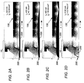
- Figures 2a to 2d show the optics simulation of electron beam generated from a cold cathode electron emitter 200 with different current densities.
- the convergent thermionic cathode is replaced with a smaller, higher current density, planar emitter, of which the emission surface is non-convergent.
- the electron beam 120 is well focused to propagate along the PPM structure.
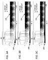
- Figures 3a to 3c present a new geometry to resolve the problems in focusing non-convergent, high current density, and high emittance cold cathode electron beams.
- a series of shaped electrostatic lenses 220 are employed to allow the control of the electric field at the cathode surface and also allows for tailoring of the electric field profile during beam acceleration.
- four lenses are used. It is appreciated that number of the lenses other than four can be selected according to specific design requirements.
- an electron beam is emitted from a cold cathode electron emitter 200 (the electron gun). To achieve the focusing effect, the lenses are simultaneously applied with different focusing voltages, which are functions of the acceleration voltage and total beam current.
- the magnitudes of the focusing voltages are limited to a range to effectively focus the electron beam and confine it within the magnetic field subsequently.
- five magnet cells of which the magnetic contours are denoted as 130, are shown in Figures 3a to 3c.
- Figure 3a the electron beam with a low current 20 mA is well focused and confined.
- the current increases up to 80 mA (with a current density of 10.2 A/cm 2 )
- the electron beam is still under a good control is laminar and scallop-free.
- the current reaches to 150 mA where Pierce geometry results in total beam reflection, as shown in Figure 2d, the electron beam is still laminar and scallop-free.
- the geometry allows focusing of all currents for 0 ⁇ I beam ⁇ 0.15A, that is, the current densities falling within the range of 0 ⁇ j k ⁇ 20 A/cm 2 and creates a scallop-free beam for injection into the RF circuit of the device.
- the expanded cathode view clearly shows the increased perpendicular velocity.
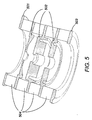
- Figure 5 shows cross section of an electron gun fabricated for a specific field emission array cold cathode emitter with 1 mm diameter emitting area.
- the series of shaped lenses 502 are clearly shown.
- the example comprises four lenses 502 and the grounded beam tunnel.
- the lenses are located in front of the emission surface (the emitter location 501) and spaced with isolation ceramics 504 from each other.
- a weld flange for anode 503 is disposed to hold the non-intercepting anode.
- an isolation ceramic 504 is also applied for isolation between the electrostatic lens 502 and the anode.
- electrostatic lenses other than four may also be used according to specific design requirement.
- electrostatic lenses are simultaneously applied with different focusing voltages. The exact magnitude of the focusing voltages applied to the electrostatic lenses can be simulated and calculated from computer program.
- Figure 6 shows a graph of potential along the axis (z) of the electron gun applied with an acceleration voltage of 3400 V and a beam current of 50 mA.
- the electron beam emitted from the emission surface starts with a negative potential.
- an ion shield is disposed, such that the electrostatic potential where the ion shield is located is positive and typically has a value of several hundred volts.
- the ion shield function is further introduced in detail in the following paragraph.
- the focusing lenses that is, the series of electrostatic lenses, the potential drops to a negative value. The potential reaches to ground in the beam tunnel.
- the emission surface of the emitter is at a large negative potential.
- the potential profile is shown in Figure 6, in which the ion shield is placed immediately in front of the emission surface of the emitter where the potential is -3400V.
- the positive potential applied to the ion shield has to be sufficiently high to effect the ion shield, that is, to prevent the ion bombardment.
- any ion created downstream of the ion shield will not be affected by the large negative cathode potential.
- Pierce gun uses two focusing elements in a very specific geometry to create the potential profile required to focus the electron beam. One of these two elements (the focus electrode) is biased at the emitter potential and the other (the anode) at ground potential. If an attempt is made to bias one of these two elements to a positive potential, the focusing property of the Pierce electron gun is lost.
- Figure 7 illustrates the I-V parameter region of for laminar, scallop-free beam generation using a conventional Pierce electron gun and the cold cathode electron gun provided by the present invention.
- the narrow region 720 that provides a high-qualify focused beam by the conventional thermionic emitter is enclosed in the very broad region 710 that provides the high-quality focused beam by the cold cathode electron gun provided by the invention.
- This broad coverage indicates the invention is able to provide high-quality focus for any combination of beam acceleration voltage and beam current and greatly exceeds the capability of Pierce geometry.
- Figure 8 shows a relationship between the collector/helix current, versus the total beam current beam. This graph further verifies that the cold cathode electron gun effectively focuses the electron beam by incorporating the electron gun into an FEA-TWT structure.
- the helix and collector current of the device are functions of total beam current.
- the collector is located about 10 cm from the electron gun.
- the helix is located along the entire path between the electron gun and the collector. If the required focusing were not realized, that is, without the series of electrostatic lenses used in the above embodiment, the helix current would increase dramatically as total beam current increases. Instead of having the helix current increase dramatically with the beam current, the invention obtains a constant near-zero helix current.
Landscapes
- Cold Cathode And The Manufacture (AREA)
- Electron Sources, Ion Sources (AREA)
Abstract
Description
Claims (13)
- An apparatus of focusing a high-current-density electron beam emitted from a cold cathode electron emitter, comprising a series of shaped electrostatic lense, located in front an emission surface of the cold cathode electron emitter.
- The apparatus according to claim 1, wherein the cold cathode electron emitter comprises a non-convergent emission surface, from which the high-current-density electron beam is emitted.
- The apparatus according to claim 1, wherein the series of shaped electrostatic lenses comprises four electrostatic lenses.
- The apparatus according to claim 1, further comprising an isolation ceramic between every neighboring two of the electrostatic lenses for isolation.
- The apparatus according to claim 1, wherein the cold cathode electron emitter further comprises a weld flange holding an anode in front of the series of electrostatic lenses.
- The apparatus according to claim 5, further comprising an isolation ceramic between one of the electrostatic lenses that is closest to the anode and the anode for isolation.
- The apparatus according to claim 1, further comprising an ion shield in front of the emission surface.
- The apparatus according to claim 7, wherein the ion shield includes applying a positive potential between the emission surface and a grounded body of the cold cathode electron emitter, wherein the positive potential is sufficiently high to prevent ion bombardment.
- The apparatus according to claim 1, wherein the current density range of the high-current-density electron beam is between about 0 A/cm2 to about 20 A/cm2.
- A method for focusing a high-current-density electron beam emitted from a cold cathode electron emitter, comprising the steps of:providing a series of electrostatic lenses in front of an emission surface of the cold cathode electron emitter; andapplying various voltages to each of the electrostatic lenses simultaneously, wherein the voltages are simulated and calculated with certain values to result a well-focused and confined laminar electron beam.
- The method according to claim 10, further comprising a step of providing an ion shield in front of an emission surface of the cold cathode electron emitter.
- The method according to claim 10, further comprising a step of providing the electron beam with a current density between 0 A/cm2 to 20 A/cm2.
- A cold cathode electron emission system, comprising:an electron gun, with a planar emission surface, from where a high-current-density electron beam is emitted;an ion shield, in front of the planar emission surface; anda series of electrostatic lenses, in front of the ion shield, from which the high-current-density electron beam is focused and then enters a magnetic field.
Applications Claiming Priority (2)
| Application Number | Priority Date | Filing Date | Title |
|---|---|---|---|
| US57623 | 1987-06-03 | ||
| US10/057,623 US6683414B2 (en) | 2001-10-25 | 2001-10-25 | Ion-shielded focusing method for high-density electron beams generated by planar cold cathode electron emitters |
Publications (2)
| Publication Number | Publication Date |
|---|---|
| EP1306871A2 true EP1306871A2 (en) | 2003-05-02 |
| EP1306871A3 EP1306871A3 (en) | 2004-04-21 |
Family
ID=22011748
Family Applications (1)
| Application Number | Title | Priority Date | Filing Date |
|---|---|---|---|
| EP02257165A Withdrawn EP1306871A3 (en) | 2001-10-25 | 2002-10-16 | Apparatus and method for focusing high-density electron beam emitted from planar cold cathode electron emitter |
Country Status (2)
| Country | Link |
|---|---|
| US (1) | US6683414B2 (en) |
| EP (1) | EP1306871A3 (en) |
Cited By (3)
| Publication number | Priority date | Publication date | Assignee | Title |
|---|---|---|---|---|
| GB2406704A (en) * | 2003-09-30 | 2005-04-06 | Ims Nanofabrication Gmbh | Particle-optic electrostatic lens |
| KR101357957B1 (en) * | 2012-02-23 | 2014-02-05 | 선문대학교 산학협력단 | Electrostatic electrode having convexities or concavities around the aperture thereof |
| CN109088610A (en) * | 2018-08-16 | 2018-12-25 | 电子科技大学 | Cold cathode orthogonal field amplifier and application structure thereof |
Families Citing this family (5)
| Publication number | Priority date | Publication date | Assignee | Title |
|---|---|---|---|---|
| US8129910B2 (en) * | 2009-06-23 | 2012-03-06 | L-3 Communications Corporation | Magnetically insulated cold-cathode electron gun |
| WO2013004514A1 (en) | 2011-07-01 | 2013-01-10 | Paul Scherrer Institut | Field emission cathode structure and driving method thereof |
| US9697988B2 (en) | 2015-10-14 | 2017-07-04 | Advanced Ion Beam Technology, Inc. | Ion implantation system and process |
| CN111696847A (en) * | 2020-06-29 | 2020-09-22 | 北京卫星环境工程研究所 | Electron source suitable for satellite-borne atmosphere in-situ detection |
| CN115326127B (en) * | 2021-05-11 | 2025-05-27 | 中国科学院国家空间科学中心 | A device and method for measuring atmospheric wind field in spacecraft orbit |
Family Cites Families (27)
| Publication number | Priority date | Publication date | Assignee | Title |
|---|---|---|---|---|
| BE532870A (en) * | 1953-11-13 | |||
| US3931519A (en) * | 1972-02-14 | 1976-01-06 | American Optical Corporation | Field emission electron gun |
| CA976594A (en) * | 1972-02-14 | 1975-10-21 | Vincent J. Coates | Field emission electron gun |
| DE2855864A1 (en) * | 1978-12-22 | 1980-07-10 | Ibm Deutschland | ION SOURCE, ESPECIALLY FOR ION IMPLANTATION PLANTS |
| JPS595552A (en) * | 1982-06-30 | 1984-01-12 | Jeol Ltd | Electron gun |
| US4740705A (en) | 1986-08-11 | 1988-04-26 | Electron Beam Memories | Axially compact field emission cathode assembly |
| US4886969A (en) | 1988-12-16 | 1989-12-12 | Hughes Aircraft Company | Cluster beam apparatus utilizing cold cathode cluster ionizer |
| US5241182A (en) * | 1991-06-18 | 1993-08-31 | Fei Company | Precision electrostatic lens system and method of manufacture |
| EP0545621B1 (en) * | 1991-11-29 | 1995-09-06 | Motorola, Inc. | Method of forming a field emission device with integrally formed electrostatic lens |
| JP2653008B2 (en) * | 1993-01-25 | 1997-09-10 | 日本電気株式会社 | Cold cathode device and method of manufacturing the same |
| US5497053A (en) | 1993-11-15 | 1996-03-05 | The United States Of America As Represented By The Secretary Of The Navy | Micro-electron deflector |
| US5955849A (en) * | 1993-11-15 | 1999-09-21 | The United States Of America As Represented By The Secretary Of The Navy | Cold field emitters with thick focusing grids |
| JP2809125B2 (en) * | 1995-02-27 | 1998-10-08 | 日本電気株式会社 | Field emission cold cathode with focusing electrode |
| US5898269A (en) * | 1995-07-10 | 1999-04-27 | The Board Of Trustees Of The Leland Stanford Jr. University | Electron sources having shielded cathodes |
| DE19534228A1 (en) * | 1995-09-15 | 1997-03-20 | Licentia Gmbh | Cathode ray tube with field emission cathode |
| KR100349901B1 (en) * | 1996-01-30 | 2002-12-28 | 삼성에스디아이 주식회사 | Electron gun for colored cathode ray tube |
| JP3026484B2 (en) * | 1996-08-23 | 2000-03-27 | 日本電気株式会社 | Field emission cold cathode |
| KR100365444B1 (en) * | 1996-09-18 | 2004-01-24 | 가부시끼가이샤 도시바 | Vacuum micro device and image display device using the same |
| US5908699A (en) * | 1996-10-11 | 1999-06-01 | Skion Corporation | Cold cathode electron emitter and display structure |
| JP2939943B2 (en) | 1996-11-01 | 1999-08-25 | 日本電気株式会社 | Cold cathode electron gun and microwave tube device having the same |
| JP3080021B2 (en) * | 1997-02-10 | 2000-08-21 | 日本電気株式会社 | Field emission cold cathode and method of manufacturing the same |
| JP3156763B2 (en) * | 1997-08-12 | 2001-04-16 | 日本電気株式会社 | Electrode voltage application method and apparatus for cold cathode mounted electron tube |
| US6307309B1 (en) * | 1998-08-18 | 2001-10-23 | Nec Corporation | Field emission cold cathode device and manufacturing method thereof |
| US6130507A (en) * | 1998-09-28 | 2000-10-10 | Advanced Ion Technology, Inc | Cold-cathode ion source with propagation of ions in the electron drift plane |
| US6037717A (en) * | 1999-01-04 | 2000-03-14 | Advanced Ion Technology, Inc. | Cold-cathode ion source with a controlled position of ion beam |
| US6255768B1 (en) * | 1999-07-19 | 2001-07-03 | Extreme Devices, Inc. | Compact field emission electron gun and focus lens |
| US6429596B1 (en) * | 1999-12-31 | 2002-08-06 | Extreme Devices, Inc. | Segmented gate drive for dynamic beam shape correction in field emission cathodes |
-
2001
- 2001-10-25 US US10/057,623 patent/US6683414B2/en not_active Expired - Fee Related
-
2002
- 2002-10-16 EP EP02257165A patent/EP1306871A3/en not_active Withdrawn
Cited By (6)
| Publication number | Priority date | Publication date | Assignee | Title |
|---|---|---|---|---|
| GB2406704A (en) * | 2003-09-30 | 2005-04-06 | Ims Nanofabrication Gmbh | Particle-optic electrostatic lens |
| GB2406704B (en) * | 2003-09-30 | 2007-02-07 | Ims Nanofabrication Gmbh | Particle-optic electrostatic lens |
| US7199373B2 (en) | 2003-09-30 | 2007-04-03 | Ims Nanofabrication Gmbh | Particle-optic electrostatic lens |
| KR101357957B1 (en) * | 2012-02-23 | 2014-02-05 | 선문대학교 산학협력단 | Electrostatic electrode having convexities or concavities around the aperture thereof |
| CN109088610A (en) * | 2018-08-16 | 2018-12-25 | 电子科技大学 | Cold cathode orthogonal field amplifier and application structure thereof |
| CN109088610B (en) * | 2018-08-16 | 2021-04-13 | 电子科技大学 | A cold cathode quadrature field amplifier and its application structure |
Also Published As
| Publication number | Publication date |
|---|---|
| US20030080689A1 (en) | 2003-05-01 |
| EP1306871A3 (en) | 2004-04-21 |
| US6683414B2 (en) | 2004-01-27 |
Similar Documents
| Publication | Publication Date | Title |
|---|---|---|
| EP0364574B1 (en) | Plasma-assisted high-power microwave generator | |
| US6985553B2 (en) | Ultra-short ion and neutron pulse production | |
| US5391962A (en) | Electron beam driven negative ion source | |
| EP0261198B1 (en) | Plasma-anode electron gun | |
| US6683414B2 (en) | Ion-shielded focusing method for high-density electron beams generated by planar cold cathode electron emitters | |
| JP5337028B2 (en) | apparatus | |
| Harris | A tutorial on vacuum surface flashover | |
| JPH02148700A (en) | Accelerator combining ion drawing of high neutron flux neutron tube | |
| CN101501811B (en) | X-ray tube and method of voltage supplying of an ion deflecting and collecting setup of an X-ray tube | |
| Tang et al. | Planar lenses for field‐emitter arrays | |
| JP3156763B2 (en) | Electrode voltage application method and apparatus for cold cathode mounted electron tube | |
| Manwani et al. | Asymmetric beam driven plasma wakefields at the AWA | |
| GB2295485A (en) | Ion beam extraction and acceleration | |
| US10431415B2 (en) | X-ray tube ion barrier | |
| Tang et al. | Free electron micro-lasers | |
| JPH11232995A (en) | How the electron tube works | |
| US4024465A (en) | Generation of corona for laser excitation | |
| US4149055A (en) | Focusing ion accelerator | |
| Carlsten et al. | Emittance studies at the Los Alamos National Laboratory free electron laser | |
| Deichuli et al. | High power hydrogen neutral beam injector with focusing for plasma heating | |
| JP2778227B2 (en) | Ion source | |
| Johnson et al. | PBFA II applied B-field ion diode proton beam characteristics | |
| Bhupendrasingh | Studies on Extraction of an Ion beam and its Transport from a Multi-Cusp Gridded Ion Source | |
| JP3341497B2 (en) | High frequency type charged particle accelerator | |
| JPH0982254A (en) | Rf electron gun, cathode for rf electron gun and manufacture of the cathode |
Legal Events
| Date | Code | Title | Description |
|---|---|---|---|
| PUAI | Public reference made under article 153(3) epc to a published international application that has entered the european phase |
Free format text: ORIGINAL CODE: 0009012 |
|
| AK | Designated contracting states |
Designated state(s): AT BE BG CH CY CZ DE DK EE ES FI FR GB GR IE IT LI LU MC NL PT SE SK TR |
|
| AX | Request for extension of the european patent |
Extension state: AL LT LV MK RO SI |
|
| PUAL | Search report despatched |
Free format text: ORIGINAL CODE: 0009013 |
|
| AK | Designated contracting states |
Kind code of ref document: A3 Designated state(s): AT BE BG CH CY CZ DE DK EE ES FI FR GB GR IE IT LI LU MC NL PT SE SK TR |
|
| AX | Request for extension of the european patent |
Extension state: AL LT LV MK RO SI |
|
| RIC1 | Information provided on ipc code assigned before grant |
Ipc: 7H 01J 23/083 B Ipc: 7H 01J 3/02 A |
|
| 17P | Request for examination filed |
Effective date: 20040817 |
|
| AKX | Designation fees paid |
Designated state(s): FR GB |
|
| REG | Reference to a national code |
Ref country code: DE Ref legal event code: 8566 |
|
| STAA | Information on the status of an ep patent application or granted ep patent |
Free format text: STATUS: THE APPLICATION IS DEEMED TO BE WITHDRAWN |
|
| 18D | Application deemed to be withdrawn |
Effective date: 20080503 |