EP1306839B1 - Method and apparatus of recording data optimally onto a disk recorded in multiple speed zones - Google Patents
Method and apparatus of recording data optimally onto a disk recorded in multiple speed zones Download PDFInfo
- Publication number
- EP1306839B1 EP1306839B1 EP02018709A EP02018709A EP1306839B1 EP 1306839 B1 EP1306839 B1 EP 1306839B1 EP 02018709 A EP02018709 A EP 02018709A EP 02018709 A EP02018709 A EP 02018709A EP 1306839 B1 EP1306839 B1 EP 1306839B1
- Authority
- EP
- European Patent Office
- Prior art keywords
- recording
- speed
- level
- writing
- data
- Prior art date
- Legal status (The legal status is an assumption and is not a legal conclusion. Google has not performed a legal analysis and makes no representation as to the accuracy of the status listed.)
- Expired - Lifetime
Links
Images



Classifications
-
- G—PHYSICS
- G11—INFORMATION STORAGE
- G11B—INFORMATION STORAGE BASED ON RELATIVE MOVEMENT BETWEEN RECORD CARRIER AND TRANSDUCER
- G11B7/00—Recording or reproducing by optical means, e.g. recording using a thermal beam of optical radiation by modifying optical properties or the physical structure, reproducing using an optical beam at lower power by sensing optical properties; Record carriers therefor
- G11B7/004—Recording, reproducing or erasing methods; Read, write or erase circuits therefor
- G11B7/0045—Recording
-
- G—PHYSICS
- G11—INFORMATION STORAGE
- G11B—INFORMATION STORAGE BASED ON RELATIVE MOVEMENT BETWEEN RECORD CARRIER AND TRANSDUCER
- G11B19/00—Driving, starting, stopping record carriers not specifically of filamentary or web form, or of supports therefor; Control thereof; Control of operating function ; Driving both disc and head
- G11B19/20—Driving; Starting; Stopping; Control thereof
- G11B19/26—Speed-changing arrangements; Reversing arrangements; Drive-transfer means therefor
Definitions
- the present invention relates to method and apparatus of recording data onto a disk recording medium in zoned-CLV mode while adjusting recording speed and recording condition adequately at every speed change point between zones.
- a disk device for writing/reading data to/from a disk recording medium equips with a memory that stores an optimal write strategy of each disk manufacturer, which is identified by a disk code, for each recording speed in order to conduct optimal writing onto an inserted writable disk.
- the disk device detects a disk code of an inserted disk first, selects an optimal write strategy stored in the memory based on the detected disk code and a recording speed set by a user, and applies the selected write strategy to a recording mechanism that conducts the requested data record.
- the selected optimal write strategy is applied to data recording onto a program area of the inserted disk as well as test recording for detecting an optimal writing power.
- CLV Constant Linear Velocity
- CAV Constant Angular Velocity
- a zoned-CLV manner has been introduced.
- a disk is partitioned into several zones, and CLV is applied within individual zones whereas CAV is applied between zones, as depicted in Fig. 2 . Therefore, the zoned-CLV inevitably has recording speed transition points (marked 'a','b','c' in Fig. 2 ).
- recording speed at next zone must be maintained as previous even though recording zone is changed. For example, if record is started at 12X speed at the zone 'a-b' of Fig. 2 , 12X speed 201 is still maintained at next zones 'b-c' and 'c-d'.
- a recording position goes outward along a spiral track while recording is progressed.
- media characteristic such as thickness is different between inner and outer area, so that it is necessary to compensate such a difference to keep a writing power optimal.
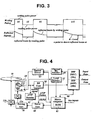
- a disk device detects a B-level reflected by a certain writing pulse, e.g., 11T signal at a start-up operation as shown in Fig. 3 , and memorizes the detected level as a base one. Afterwards, if a detected B-level deviates from the memorized base level as a recording position goes outward during data recording, the disk device adjusts an optimal writing power minutely to compensate the B-level deviation. This compensating operation is called a running OPC (Optimal Power Calibration).
- a recording speed must be changed every zone change in the zoned-CLV recording mode if data is to be recorded at maximum recording speed allowable at each zone.
- recording speed becomes different from start speed at which the base B-level is detected.
- running OPC is progressed on a basis of the initial memorized B-level, a minutely-adjusted writing power can not be optimal.
- EP-A-0 910 069 discloses an optical disk divided into a plurality of zones, each zone including a plurality of tracks each including a constant number of sectors.
- the optical disk includes a user use region, a manufacture region and a guard region.
- An MCAV recording system is used. A recording/reproduction condition is changed at every zone or at every block.
- US-A-6,052,347 describes a method and system of determining a recording power distribution in a modified constant linear velocity (ZCLV) formatted optical disk with multiple data recording areas and optimum power control (OPC) areas encompassing each data recording area.
- ZCLV constant linear velocity
- OPC optimum power control
- JP-A-10040548 discloses an apparatus for recording data onto a disk recording medium on a basis of a running OPC according to the preamble of claim 5.
- a method of recording data onto a disk recording medium in accordance with the present invention detects a current recording position while recording data along a track of a disk recording medium, adjusts a recording speed and detects newly a reflected level by a writing pulse after speed-up by the adjustment if the detected current recording position is among predetermined speed-change locations, and sets the detected new level as a base one for a running OPC.
- Fig. 4 is a simplified block diagram of a disk device in which an optimal data recording method of the present invention is embedded.
- the disk drive of Fig. 4 comprises a digital recording signal processing unit 30a for converting input data into record-formatted EFM (Eight to Fifteen Modulation) data while adding additional data such as error correction codes (ECC); a channel bit encoder 40 for converting the record-formatted data into writing signals; an optical driver 41 for yielding signals to drive an LD (Laser Diode); an optical pickup 20 for writing signals onto surface of a writable disk 10 and for reading written signals from the surface of the optical disk 10; an R/F unit 50 for producing binarized signals and TE (Tracking Error) and FE (Focusing Error) signal through filtering and combining the signals detected by the pickup 20; an ATIP decoder 51 for producing ATIP (Absolute Time In Pregroove) frames by decoding a wobble signal detected from the writable disk 10; a level detector 52 for detecting a beam level reflected from marks or spaces formed on the disk 10 by writing signals; a driving unit 70 for driving
- Fig. 5 is a flowchart of a preferable embodiment of an optimal data recording method in accordance with the present invention.
- the flow chart of Fig. 5 conducted by the disk device structured as Fig. 4 is explained in detail below.
- a writable disk 10 is normally placed onto a tray (not shown) equipped in the disk device (S10) it is rotated at a constant speed under control of the microcomputer 80.
- the microcomputer 80 analyses ATIP frames outputted from the ATIP decoder 51 to search frames decoded from a lead-in area for the first (Frame No. N) and the 11th (Frame No. N+10) frame, namely, the first and second special information.
- Each ATIP frame is composed of three bytes called 'Minutes', 'Seconds' and 'Frames'. MSBs of three bytes of the two frames are '101' and '110', respectively.
- the first frame includes information about reference of an optimal writing power and disk type while the 11th frame includes information on start time of a lead-in area.
- the microcomputer 80 If the two frames are found, the microcomputer 80 reads out three bits of M2:M3:M4, which is indicative of the reference of optimal writing power, from the first frame and entire bits from the 11th frame (S11). At this time, the microcomputer 80 replaces three bits of M1:S1:F1 with '100' for the 11th frame.
- the start time written in the 11th frame has different value if a manufacturing company is different. Therefore, the microcomputer 80 can identify which company has manufactured the inserted disk 10 based on the read-out start time. Instead of the 11th frame, the microcomputer 80 can also identify the manufacturing company or disk based on start time of a lead-out area written in the 21st (Frame No. N+20) frame, namely, the third special information.
- the microcomputer 80 conducts an OPC in a PCA area of the disk 10.
- OPC the microcomputer 80 records test data while adjusting a writing power on a basis of the reference of optimal writing power, and reads the recorded test data. Based on characteristic of the read test data, an actual optimal recording power is determined (S11).
- a B-level by a 11T writing signal is also detected and memorized as a base value (S11).
- the microcomputer 80 determines where data is to be recorded, namely, a recording zone and position within the zone. If zone and position are determined, maximum speed allowable at the zone is determined too. For example, if record starts from 601 as shown in Fig. 6 , the maximum speed is 8X.
- the microcomputer 80 selects a write strategy most suitable to the identified disk code (company code) and the determined current recording speed from the internal ROM 81 (S12).
- the microcomputer 80 conducts data record at 8X that is the highest speed allowed at the start zone after or while applying the selected write strategy to the optical driver 41 (S14). Because the recording speed is same as when the base B-level is detected while record is progressed within the start zone, the running OPC is still conducted to compensate B-level difference on a basis of the initial base B-level.
- Input data is encoded with parity by the digital recording signal processing unit 30a to form ECC blocks to improve reliability of data recording/reproduction.
- Each ECC block is outputted in EFM-formatted serial bits from the digital recording signal processing unit 30a to the channel bit encoder 40 that modulates the serial bits into NRZ signals.
- the optical driver 41 outputs PWM (Pulse-Width Modulated) writing signals according to the modulated NRZ signals while adjusting step level and/or duration of the PWM signal in accordance with the selected write strategy.
- the outputs of the optical driver 41 are converted by the optical pickup 20 to light beams that form respective marks and spaces along a track of the writable disk 10.
- the microcomputer 80 continues to check whether a current recording position is among speed-change points, e.g., the points 'a', 'b', and 'c' marked in Fig. 6 (S15). If it is not, the microcomputer 80 conducts the above recording operation and the running OPC on a basis of the initial base B-level. However, if it is one of the speed change points, e.g., the point 'a' of Fig. 6 (S20), the microcomputer 80 controls the driving unit 70 through the servo unit 60 to increase the recording speed from 8X to 12X that is maximum speed at the second zone 'zone 2' (S21).
- speed-change points e.g., the points 'a', 'b', and 'c' marked in Fig. 6 (S15). If it is not, the microcomputer 80 conducts the above recording operation and the running OPC on a basis of the initial base B-level. However, if it is one of the speed change points, e.g., the
- Whether the current recording position is at one of the speed change points, namely, each boundary between zones is determined based on a time code of an ATIP frame outputted from the ATIP decoder 51 during data record.
- the microcomputer 80 regards the current position as one of the speed change points when the time code written in an ATIP frame is indicative of the boundary, 'a', 'b', or 'c' marked in Fig. 6 .
- the microcomputer 80 reads out a write strategy for the adjusted 12X speed from the internal ROM 81 (S22), and sets step level and/or duration of each writing pulse to the optical driver 41 as defined by the read write strategy (S23).
- the microcomputer 80 conducts test data recording on a zone buffer between neighboring zones, marked 'A' in Fig. 6 , at the increased recording speed 12X while storing B-level values detected by the level detector 52 from successive writing signals.
- the microcomputer 80 calculates an average of the stored B-level values, and then sets the average to a new base B-level (S24).
- While recording test data onto the zone buffer the input data is buffered.
- the buffered data and subsequent data starts to be recorded.
- the running OPC is conducted with the new base B-level determined at the 12X speed (S25).
- the above-explained optimal data recording method and apparatus can record input data onto a writable disk with the most suitable writing condition at the highest allowable speed.
Landscapes
- Optical Recording Or Reproduction (AREA)
Description
- The present invention relates to method and apparatus of recording data onto a disk recording medium in zoned-CLV mode while adjusting recording speed and recording condition adequately at every speed change point between zones.
- In general, a disk device for writing/reading data to/from a disk recording medium equips with a memory that stores an optimal write strategy of each disk manufacturer, which is identified by a disk code, for each recording speed in order to conduct optimal writing onto an inserted writable disk. Thus, when a data record is requested, the disk device detects a disk code of an inserted disk first, selects an optimal write strategy stored in the memory based on the detected disk code and a recording speed set by a user, and applies the selected write strategy to a recording mechanism that conducts the requested data record.
- Consequently, in the conventional art, the selected optimal write strategy is applied to data recording onto a program area of the inserted disk as well as test recording for detecting an optimal writing power.
- Meantime, data is recorded onto a rotating disk in CLV (Constant Linear Velocity) 101 or CAV (Constant Angular Velocity)
manner 102 as shown inFig. 1 . In the CLV manner, rotating speed must be decreased gradually as a recording position goes outward, so that high speed recording can not achieved by the CLV manner. In CAV manner, recording speed is increased as a recording position goes outward, however, it may be too high to record data onto a track at an outer area. To suppress non-recordable high speed, rotating speed is set such that recording speed at an inner area is very low. - For resolving the respective drawbacks of the two recording manners, a zoned-CLV manner has been introduced. In the zoned-CLV manner, a disk is partitioned into several zones, and CLV is applied within individual zones whereas CAV is applied between zones, as depicted in
Fig. 2 . Therefore, the zoned-CLV inevitably has recording speed transition points (marked 'a','b','c' inFig. 2 ). - In case that data is to be recorded at maximum recording speed of each zone, if an initial optimal write strategy selected at start up is maintained up to record end, the write strategy is not optimal after recording zone is changed because recording speed has been increased at a changed zone. Consequently, overall recording operation is not conducted optimally.
- For ensuring optimal recording up to record end, recording speed at next zone must be maintained as previous even though recording zone is changed. For example, if record is started at 12X speed at the zone 'a-b' of
Fig. 2 ,12X speed 201 is still maintained at next zones 'b-c' and 'c-d'. - However, such a record can not use maximum recording speed allowable at each zone, so that recording time takes relatively long in comparison with maximum-speed recording at each zone.
- Meantime, a recording position goes outward along a spiral track while recording is progressed. However, media characteristic such as thickness is different between inner and outer area, so that it is necessary to compensate such a difference to keep a writing power optimal. For compensation, a disk device detects a B-level reflected by a certain writing pulse, e.g., 11T signal at a start-up operation as shown in
Fig. 3 , and memorizes the detected level as a base one. Afterwards, if a detected B-level deviates from the memorized base level as a recording position goes outward during data recording, the disk device adjusts an optimal writing power minutely to compensate the B-level deviation. This compensating operation is called a running OPC (Optimal Power Calibration). - By the way, as aforementioned, a recording speed must be changed every zone change in the zoned-CLV recording mode if data is to be recorded at maximum recording speed allowable at each zone. Thus, if recording zone is changed, recording speed becomes different from start speed at which the base B-level is detected. In spite of speed change, if running OPC is progressed on a basis of the initial memorized B-level, a minutely-adjusted writing power can not be optimal.
-
EP-A-0 910 069 discloses an optical disk divided into a plurality of zones, each zone including a plurality of tracks each including a constant number of sectors. In order to attain a high recording density and a high transfer rate the optical disk includes a user use region, a manufacture region and a guard region. An MCAV recording system is used. A recording/reproduction condition is changed at every zone or at every block. -
US-A-6,052,347 describes a method and system of determining a recording power distribution in a modified constant linear velocity (ZCLV) formatted optical disk with multiple data recording areas and optimum power control (OPC) areas encompassing each data recording area. -
JP-A-10040548 - It is an object of the present invention to provide method and apparatus that record data onto a disk recording medium in zoned-CLV manner while detecting speed transition points of the disk recording medium and adjusting a recording condition as well as a recording speed every detection of speed transition point.
- It is another obj ect of the present invention to provide method and apparatus that record data onto a disk recording medium in zoned-CLV manner while not only adjusting a recording speed but also resetting a base value for a running OPC to be used after speed change whenever a speed transition point of the disk recording medium is detected.
- A method of recording data onto a disk recording medium in accordance with the present invention detects a current recording position while recording data along a track of a disk recording medium, adjusts a recording speed and detects newly a reflected level by a writing pulse after speed-up by the adjustment if the detected current recording position is among predetermined speed-change locations, and sets the detected new level as a base one for a running OPC.
- The accompanying drawings, which are included to provide a further understanding of the present invention, illustrate the preferred embodiments of the invention, and together with the description, serve to explain the principles of the present invention, and wherein:
-
Fig. 1 shows two data recording manners for a rotating disk; -
Fig. 2 shows a zoned-CLV recording manner; -
Fig. 3 shows relationship between writing/reading pulses and reflected level thereby; -
Fig. 4 is a simplified block diagram of a disk device in which an optimal data recording method of the present invention is embedded; -
Fig. 5 is a flow chart of a preferable embodiment of an optical disk and maximum recording speed allowable in each zone. - In order that the invention may be fully understood, a preferred embodiment thereof will now be described with reference to the accompanying drawings.
-
Fig. 4 is a simplified block diagram of a disk device in which an optimal data recording method of the present invention is embedded. - The disk drive of
Fig. 4 comprises a digital recordingsignal processing unit 30a for converting input data into record-formatted EFM (Eight to Fifteen Modulation) data while adding additional data such as error correction codes (ECC); achannel bit encoder 40 for converting the record-formatted data into writing signals; anoptical driver 41 for yielding signals to drive an LD (Laser Diode); anoptical pickup 20 for writing signals onto surface of awritable disk 10 and for reading written signals from the surface of theoptical disk 10; an R/F unit 50 for producing binarized signals and TE (Tracking Error) and FE (Focusing Error) signal through filtering and combining the signals detected by thepickup 20; anATIP decoder 51 for producing ATIP (Absolute Time In Pregroove) frames by decoding a wobble signal detected from thewritable disk 10; alevel detector 52 for detecting a beam level reflected from marks or spaces formed on thedisk 10 by writing signals; adriving unit 70 for driving asled motor 11a to move theoptical pickup 20 and aspindle motor 11b to rotate thedisk 10; aservo unit 60 for conducting tracking/focusing operation of an objective lens in thepickup 20 and controlling thedriving unit 70 to rotate thedisk 10 at a constant speed; a digital reproducedsignal processing unit 30b for restoring original data from the binarized signals using a self clock synchronized with the binarized signals in phase; and amicrocomputer 80 for controlling an overall recording/reproducing operation, especially, for adjusting a base B-level as well as recording speed at every speed transition point in a zoned-CLV recording manner, and changing a write strategy to be optimal to adjusted recording speed with reference to write strategies for each recording speed, classified by disk codes (or company codes), stored in aninternal ROM 81. -
Fig. 5 is a flowchart of a preferable embodiment of an optimal data recording method in accordance with the present invention. The flow chart ofFig. 5 conducted by the disk device structured asFig. 4 is explained in detail below. - If a
writable disk 10 is normally placed onto a tray (not shown) equipped in the disk device (S10) it is rotated at a constant speed under control of themicrocomputer 80. At the same time, themicrocomputer 80 analyses ATIP frames outputted from theATIP decoder 51 to search frames decoded from a lead-in area for the first (Frame No. N) and the 11th (Frame No. N+10) frame, namely, the first and second special information. Each ATIP frame is composed of three bytes called 'Minutes', 'Seconds' and 'Frames'. MSBs of three bytes of the two frames are '101' and '110', respectively. The first frame includes information about reference of an optimal writing power and disk type while the 11th frame includes information on start time of a lead-in area. - If the two frames are found, the
microcomputer 80 reads out three bits of M2:M3:M4, which is indicative of the reference of optimal writing power, from the first frame and entire bits from the 11th frame (S11). At this time, themicrocomputer 80 replaces three bits of M1:S1:F1 with '100' for the 11th frame. - The start time written in the 11th frame has different value if a manufacturing company is different. Therefore, the
microcomputer 80 can identify which company has manufactured the inserteddisk 10 based on the read-out start time. Instead of the 11th frame, themicrocomputer 80 can also identify the manufacturing company or disk based on start time of a lead-out area written in the 21st (Frame No. N+20) frame, namely, the third special information. - The
microcomputer 80 conducts an OPC in a PCA area of thedisk 10. In OPC, themicrocomputer 80 records test data while adjusting a writing power on a basis of the reference of optimal writing power, and reads the recorded test data. Based on characteristic of the read test data, an actual optimal recording power is determined (S11). - While the OPC is progressed, a B-level by a 11T writing signal is also detected and memorized as a base value (S11).
- Afterwards, the
microcomputer 80 determines where data is to be recorded, namely, a recording zone and position within the zone. If zone and position are determined, maximum speed allowable at the zone is determined too. For example, if record starts from 601 as shown inFig. 6 , the maximum speed is 8X. Themicrocomputer 80 selects a write strategy most suitable to the identified disk code (company code) and the determined current recording speed from the internal ROM 81 (S12). - If the most high-speed recording is requested from a user (S13) after the above pre-operation, the
microcomputer 80 conducts data record at 8X that is the highest speed allowed at the start zone after or while applying the selected write strategy to the optical driver 41 (S14). Because the recording speed is same as when the base B-level is detected while record is progressed within the start zone, the running OPC is still conducted to compensate B-level difference on a basis of the initial base B-level. - While the
disk 10 is rotating at maximum 8X speed to record from the first zone 'zone 1' as shown inFig. 6 , input data is recorded as follows. Input data is encoded with parity by the digital recordingsignal processing unit 30a to form ECC blocks to improve reliability of data recording/reproduction. Each ECC block is outputted in EFM-formatted serial bits from the digital recordingsignal processing unit 30a to thechannel bit encoder 40 that modulates the serial bits into NRZ signals. Theoptical driver 41 outputs PWM (Pulse-Width Modulated) writing signals according to the modulated NRZ signals while adjusting step level and/or duration of the PWM signal in accordance with the selected write strategy. The outputs of theoptical driver 41 are converted by theoptical pickup 20 to light beams that form respective marks and spaces along a track of thewritable disk 10. - During the above recording operation, the
microcomputer 80 continues to check whether a current recording position is among speed-change points, e.g., the points 'a', 'b', and 'c' marked inFig. 6 (S15). If it is not, themicrocomputer 80 conducts the above recording operation and the running OPC on a basis of the initial base B-level. However, if it is one of the speed change points, e.g., the point 'a' ofFig. 6 (S20), themicrocomputer 80 controls the drivingunit 70 through theservo unit 60 to increase the recording speed from 8X to 12X that is maximum speed at the second zone 'zone 2' (S21). - Whether the current recording position is at one of the speed change points, namely, each boundary between zones is determined based on a time code of an ATIP frame outputted from the
ATIP decoder 51 during data record. In other words, themicrocomputer 80 regards the current position as one of the speed change points when the time code written in an ATIP frame is indicative of the boundary, 'a', 'b', or 'c' marked inFig. 6 . - Then, the
microcomputer 80 reads out a write strategy for the adjusted 12X speed from the internal ROM 81 (S22), and sets step level and/or duration of each writing pulse to theoptical driver 41 as defined by the read write strategy (S23). - At the same time, the
microcomputer 80 conducts test data recording on a zone buffer between neighboring zones, marked 'A' inFig. 6 , at the increased recording speed 12X while storing B-level values detected by thelevel detector 52 from successive writing signals. At end of the zone buffer, themicrocomputer 80 calculates an average of the stored B-level values, and then sets the average to a new base B-level (S24). - While recording test data onto the zone buffer, the input data is buffered. When the second zone begins, the buffered data and subsequent data starts to be recorded. While data is recorded onto the second zone, the running OPC is conducted with the new base B-level determined at the 12X speed (S25).
- The above-explained write strategy adjustment and base B-level updating in the course of the writing process are conducted whenever the recording zone is changed, namely, at the points 'b' and 'c' in
Fig. 6 . - The above-explained optimal data recording method and apparatus can record input data onto a writable disk with the most suitable writing condition at the highest allowable speed.
- It will be apparent to those skilled in the art that various modifications and variations can be made in the present invention without departing from the scope of the invention. Thus, it is intended that the present invention cover the modifications and variations of this invention provided they come within the scope of the appended claims.
Claims (10)
- A method of recording data onto a disk recording medium, comprising the steps of:(a) detecting a current recording position while recording data along a track of the disk recording medium on the basis of a running OPC method on a basis of a preset reflected level for a writing pulse (S11 - S15);(b) adjusting a recording speed if the detected current recording position is among predetermined speed-change locations (S20, S21), and detecting a new signal level for the writing pulse reflected from the current recording position at the adjusted recording speed (S23), and setting the detected new level as a base level (S24); and(c) conducting the recording of data onto the disk recording medium at the adjusted recording speed while adjusting a writing power based on a difference between each reflected level by the writing pulse and the base level set newly (S25).
- The method of claim 1, wherein said step (c) selects a write strategy associated with the adjusted recording speed, and conducts the data record with application of the selected write strategy.
- The method of claim 1, wherein the current recording position is detected based on time codes written in ATIP frames detected during data record.
- The method of claim 1, wherein said step (b) detects reflected levels while writing pulse signals onto a buffer area reserved around the speed-change location, and sets an average of the detected levels as the base level.
- An apparatus for recording data onto a disk recording medium (10), comprising:a data writer writing input data onto the disk recording medium (10) with corresponding writing beam;a drive (11a, 11b, 60, 70) rotating the disk recording medium (10);a position detector (20) detecting location information written along a track of the disk recording medium (10);a level detector (52) detecting signal level reflected by the writing beam during data writing of said data writer; anda controller (80) adjusting a recording speed and changing a write strategy of said data writer, characterised in that said controller (80) is further adapted to set a signal level detected by said level detector (52) after the recording speed adjustment to a new base level used for minute adjustment of writing power to be kept optimal during subsequent data record, if the location information detected by said position detector (20) is indicative of one of predetermined speed-change locations.
- The apparatus of claim 5, wherein the location information is time code written in each ATIP frame that is detected during data record.
- The apparatus of claim 5, wherein the signal level is obtained in process of pulse writing onto an area right before or after each speed-change location.
- The apparatus of claim 5, wherein said controller (80) selects a write strategy associated with identifying information detected from the disk recording medium (10) and the adjusted recording speed, and replaces an old write strategy with the selected write strategy.
- The apparatus of claim 5, wherein said controller (80) adjusts a writing power of said data writer based on a difference between the new base level and a reflected signal level by the writing beam detected during the subsequent data record at the adjusted recording speed.
- The apparatus of claim 5, wherein the write strategy defines conditions regarding level and/or duration of pulse signals to be written onto the disk recording medium (10).
Applications Claiming Priority (2)
| Application Number | Priority Date | Filing Date | Title |
|---|---|---|---|
| KR2001066844 | 2001-10-29 | ||
| KR10-2001-0066844A KR100454655B1 (en) | 2001-10-29 | 2001-10-29 | An apparatus and method for controlling a recording speed of an optical disc |
Publications (3)
| Publication Number | Publication Date |
|---|---|
| EP1306839A2 EP1306839A2 (en) | 2003-05-02 |
| EP1306839A3 EP1306839A3 (en) | 2004-04-21 |
| EP1306839B1 true EP1306839B1 (en) | 2008-08-13 |
Family
ID=19715479
Family Applications (1)
| Application Number | Title | Priority Date | Filing Date |
|---|---|---|---|
| EP02018709A Expired - Lifetime EP1306839B1 (en) | 2001-10-29 | 2002-08-21 | Method and apparatus of recording data optimally onto a disk recorded in multiple speed zones |
Country Status (5)
| Country | Link |
|---|---|
| US (1) | US6906987B2 (en) |
| EP (1) | EP1306839B1 (en) |
| KR (1) | KR100454655B1 (en) |
| CN (1) | CN1286094C (en) |
| DE (1) | DE60228185D1 (en) |
Families Citing this family (19)
| Publication number | Priority date | Publication date | Assignee | Title |
|---|---|---|---|---|
| KR20040006078A (en) * | 2002-07-09 | 2004-01-24 | 주식회사 히타치엘지 데이터 스토리지 코리아 | Method for optimum recording a data on optical disc |
| KR20040090545A (en) * | 2003-04-17 | 2004-10-26 | 엘지전자 주식회사 | Apparatus and Method for Adjust Screen of The Projection TV |
| EP1629493A2 (en) * | 2003-05-19 | 2006-03-01 | Koninklijke Philips Electronics N.V. | Disc drive apparatus, and method for timing recalibration in a disc drive apparatus |
| KR20050005071A (en) * | 2003-07-01 | 2005-01-13 | 주식회사 히타치엘지 데이터 스토리지 코리아 | Method for controlling a recoding speed in optical disc device |
| JP4406260B2 (en) * | 2003-10-30 | 2010-01-27 | 株式会社日立エルジーデータストレージ | Recording power determination method and recording power control method for optical disc apparatus |
| TWI300220B (en) * | 2003-11-10 | 2008-08-21 | Tian Holdings Llc | Data writing method of optical disk |
| JP2005149579A (en) * | 2003-11-12 | 2005-06-09 | Samsung Electro Mech Co Ltd | Optical pickup device and apparatus of recording/reproducing optical disk information |
| JP2005166122A (en) * | 2003-11-28 | 2005-06-23 | Toshiba Corp | Optical disc apparatus and information reproducing method |
| KR100990654B1 (en) * | 2004-01-13 | 2010-10-29 | 주식회사 히타치엘지 데이터 스토리지 코리아 | Optimal Recording Method for Optical Discs |
| KR100684409B1 (en) * | 2004-05-19 | 2007-02-16 | 주식회사 히타치엘지 데이터 스토리지 코리아 | Optimal Recording Power Detection Apparatus and Method for Optical Disc Devices |
| KR100734316B1 (en) * | 2005-02-25 | 2007-07-02 | 삼성전자주식회사 | Optical information recording apparatus, apparatus and method for setting write strategy, and computer program thereof |
| KR100746306B1 (en) * | 2005-03-10 | 2007-08-03 | 엘지전자 주식회사 | Recording Method in Optical Recording Player with Improved Recording Quality |
| JP4248518B2 (en) * | 2005-04-28 | 2009-04-02 | 株式会社日立製作所 | Optical disc recording / reproducing apparatus and optical disc recording / reproducing method |
| TW200638362A (en) | 2005-04-29 | 2006-11-01 | Mediatek Inc | Method for controlling recording speed of multi-layer optical disk of optical disk drive |
| KR100629489B1 (en) * | 2005-05-09 | 2006-09-28 | 삼성전자주식회사 | SUS optimization method through SUS learning in recording information area with similar characteristics of user data recording point and media, and optical recording device using the same |
| US7864642B2 (en) | 2005-05-09 | 2011-01-04 | Samsung Electronics Co., Ltd. | Method of optimizing a write strategy based on an adaptive write strategy study and optical recording apparatus using the same |
| JP2007317282A (en) * | 2006-05-24 | 2007-12-06 | Fujitsu Ltd | Storage device, self-diagnosis control device, and self-diagnosis method |
| TW200917233A (en) * | 2007-10-12 | 2009-04-16 | Quanta Storage Inc | Method for adjusting recoding power |
| KR20100064127A (en) * | 2008-12-04 | 2010-06-14 | 주식회사 히타치엘지 데이터 스토리지 코리아 | Method for recording data on optical disc and optical disc apparatus |
Family Cites Families (14)
| Publication number | Priority date | Publication date | Assignee | Title |
|---|---|---|---|---|
| US5010540A (en) * | 1987-07-31 | 1991-04-23 | Sharp Kabushiki Kaisha | Apparatus for recording and reproducing information on and from an optical disk |
| EP0793221B1 (en) * | 1990-05-25 | 2006-08-02 | Hitachi, Ltd. | Optical recording method and apparatus |
| JP2605577B2 (en) * | 1993-03-19 | 1997-04-30 | ヤマハ株式会社 | Optical disk recording device |
| US6052347A (en) * | 1996-02-23 | 2000-04-18 | Ricoh Company, Ltd. | Method and apparatus for detecting optimum recording power for an optical disk |
| JPH1040548A (en) * | 1996-07-26 | 1998-02-13 | Taiyo Yuden Co Ltd | Running opc method for optical disk and optical disk recording/reproducing apparatus |
| KR100226822B1 (en) * | 1996-12-31 | 1999-10-15 | 구자홍 | Method for varying record speed according to kind of disc |
| KR100366644B1 (en) * | 1998-12-30 | 2003-02-20 | 삼성전자 주식회사 | Disc storing start location information for each zone and data management method using the same information |
| JP3528697B2 (en) * | 1999-08-31 | 2004-05-17 | ヤマハ株式会社 | Appropriate recording speed judgment method and recording speed setting method for optical disc |
| KR100339478B1 (en) * | 1999-09-18 | 2002-05-31 | 구자홍 | An apparatus and method for recording the data on a optical disc using optimal writing condition |
| KR20000012504A (en) * | 1999-09-30 | 2000-03-06 | 구자홍 | Optical disc for high speed and method for reading and writing data there for |
| TW468162B (en) * | 1999-10-13 | 2001-12-11 | Koninkl Philips Electronics Nv | Method of hiding areas on a disc like recording of the optically rewritable type |
| KR100618548B1 (en) * | 2000-01-06 | 2006-08-31 | 주식회사 엘지이아이 | Recording power control method of optical recording and reproducing apparatus |
| US7016279B2 (en) * | 2000-02-10 | 2006-03-21 | Sony Corporation | Method for recording and/or reproducing data on/from recording/recorded medium, reproducing apparatus, recording medium, method for recogizing recording/recorded medium, and method for recording and/or reproducing data for apparatus using recording/recorded medium |
| KR100746767B1 (en) * | 2000-12-26 | 2007-08-06 | 엘지전자 주식회사 | Optimal Recording Method for Optical Discs |
-
2001
- 2001-10-29 KR KR10-2001-0066844A patent/KR100454655B1/en not_active Expired - Fee Related
-
2002
- 2002-08-21 DE DE60228185T patent/DE60228185D1/en not_active Expired - Lifetime
- 2002-08-21 EP EP02018709A patent/EP1306839B1/en not_active Expired - Lifetime
- 2002-08-22 US US10/225,276 patent/US6906987B2/en not_active Expired - Fee Related
- 2002-10-29 CN CNB021482837A patent/CN1286094C/en not_active Expired - Fee Related
Also Published As
| Publication number | Publication date |
|---|---|
| CN1286094C (en) | 2006-11-22 |
| EP1306839A2 (en) | 2003-05-02 |
| US6906987B2 (en) | 2005-06-14 |
| CN1428769A (en) | 2003-07-09 |
| DE60228185D1 (en) | 2008-09-25 |
| EP1306839A3 (en) | 2004-04-21 |
| KR20030034989A (en) | 2003-05-09 |
| KR100454655B1 (en) | 2004-11-05 |
| US20030081517A1 (en) | 2003-05-01 |
Similar Documents
| Publication | Publication Date | Title |
|---|---|---|
| US6906987B2 (en) | Method and apparatus of recording data optimally onto a speed-changing disk | |
| EP1006515B1 (en) | Optical disk | |
| JP2003168216A (en) | Optical recording medium, and recording apparatus and method for optical recording medium | |
| US20050141351A1 (en) | Recording type optical disk apparatus and optical disk medium | |
| US6813107B1 (en) | Apparatus and method for detecting an optimal writing power | |
| KR100552375B1 (en) | Information recording and reproducing apparatus | |
| US7349307B2 (en) | Method of recording data optimally onto a recording medium | |
| US7355946B2 (en) | Method of recording signals onto a recording medium | |
| US7414935B2 (en) | Method of overwriting optical disk with adapting initial writing conditions | |
| US6504800B1 (en) | Optical disk and optical apparatus | |
| JP3924780B2 (en) | Laser power selection method, information recording medium, and information recording apparatus | |
| KR20060042900A (en) | Recording medium evaluation method, recording / reproducing apparatus, and recording medium | |
| US20070274178A1 (en) | Information Recording Medium, Information Recording Device And Method, Information Reproducing Device And Method, And Computer Program | |
| US20080192598A1 (en) | Recording System For Setting Write Strategy | |
| JPH08329469A (en) | Data recorder | |
| JP2002324322A (en) | Optical disk device, information processing device and optical disk recording method | |
| JP2003331427A (en) | Optical information recording / reproducing device | |
| US7561507B2 (en) | Information recording and reproducing apparatus | |
| KR20050028043A (en) | Rotation speed control for recording information | |
| US20070047407A1 (en) | System and method for writing power control during recording | |
| JP2005071470A (en) | Information recording / reproducing device | |
| JP2002216350A (en) | Recording device | |
| US20020064119A1 (en) | Method for overwriting data in linking loss area | |
| KR20040002366A (en) | Optimal Recording method onto a Recording Medium | |
| KR20020094532A (en) | Method for recording the data on a optical disc using optimal writing power |
Legal Events
| Date | Code | Title | Description |
|---|---|---|---|
| PUAI | Public reference made under article 153(3) epc to a published international application that has entered the european phase |
Free format text: ORIGINAL CODE: 0009012 |
|
| AK | Designated contracting states |
Designated state(s): AT BE BG CH CY CZ DE DK EE ES FI FR GB GR IE IT LI LU MC NL PT SE SK TR |
|
| AX | Request for extension of the european patent |
Extension state: AL LT LV MK RO SI |
|
| PUAL | Search report despatched |
Free format text: ORIGINAL CODE: 0009013 |
|
| AK | Designated contracting states |
Kind code of ref document: A3 Designated state(s): AT BE BG CH CY CZ DE DK EE ES FI FR GB GR IE IT LI LU MC NL PT SE SK TR |
|
| AX | Request for extension of the european patent |
Extension state: AL LT LV MK RO SI |
|
| RIC1 | Information provided on ipc code assigned before grant |
Ipc: 7G 11B 7/00 A Ipc: 7G 11B 20/12 B Ipc: 7G 11B 7/125 B Ipc: 7G 11B 19/26 B |
|
| 17P | Request for examination filed |
Effective date: 20041020 |
|
| AKX | Designation fees paid |
Designated state(s): DE FR GB NL |
|
| 17Q | First examination report despatched |
Effective date: 20060726 |
|
| GRAP | Despatch of communication of intention to grant a patent |
Free format text: ORIGINAL CODE: EPIDOSNIGR1 |
|
| GRAS | Grant fee paid |
Free format text: ORIGINAL CODE: EPIDOSNIGR3 |
|
| GRAA | (expected) grant |
Free format text: ORIGINAL CODE: 0009210 |
|
| AK | Designated contracting states |
Kind code of ref document: B1 Designated state(s): DE FR GB NL |
|
| REG | Reference to a national code |
Ref country code: GB Ref legal event code: FG4D |
|
| REF | Corresponds to: |
Ref document number: 60228185 Country of ref document: DE Date of ref document: 20080925 Kind code of ref document: P |
|
| PLBE | No opposition filed within time limit |
Free format text: ORIGINAL CODE: 0009261 |
|
| STAA | Information on the status of an ep patent application or granted ep patent |
Free format text: STATUS: NO OPPOSITION FILED WITHIN TIME LIMIT |
|
| 26N | No opposition filed |
Effective date: 20090514 |
|
| PGFP | Annual fee paid to national office [announced via postgrant information from national office to epo] |
Ref country code: FR Payment date: 20110728 Year of fee payment: 10 |
|
| PGFP | Annual fee paid to national office [announced via postgrant information from national office to epo] |
Ref country code: DE Payment date: 20110712 Year of fee payment: 10 Ref country code: GB Payment date: 20110712 Year of fee payment: 10 |
|
| PGFP | Annual fee paid to national office [announced via postgrant information from national office to epo] |
Ref country code: NL Payment date: 20110715 Year of fee payment: 10 |
|
| REG | Reference to a national code |
Ref country code: NL Ref legal event code: V1 Effective date: 20130301 |
|
| GBPC | Gb: european patent ceased through non-payment of renewal fee |
Effective date: 20120821 |
|
| PG25 | Lapsed in a contracting state [announced via postgrant information from national office to epo] |
Ref country code: NL Free format text: LAPSE BECAUSE OF NON-PAYMENT OF DUE FEES Effective date: 20130301 |
|
| REG | Reference to a national code |
Ref country code: FR Ref legal event code: ST Effective date: 20130430 |
|
| PG25 | Lapsed in a contracting state [announced via postgrant information from national office to epo] |
Ref country code: DE Free format text: LAPSE BECAUSE OF NON-PAYMENT OF DUE FEES Effective date: 20130301 Ref country code: GB Free format text: LAPSE BECAUSE OF NON-PAYMENT OF DUE FEES Effective date: 20120821 |
|
| PG25 | Lapsed in a contracting state [announced via postgrant information from national office to epo] |
Ref country code: FR Free format text: LAPSE BECAUSE OF NON-PAYMENT OF DUE FEES Effective date: 20120831 |
|
| REG | Reference to a national code |
Ref country code: DE Ref legal event code: R119 Ref document number: 60228185 Country of ref document: DE Effective date: 20130301 |