EP1306655A1 - Pressure sensor - Google Patents
Pressure sensor Download PDFInfo
- Publication number
- EP1306655A1 EP1306655A1 EP00948332A EP00948332A EP1306655A1 EP 1306655 A1 EP1306655 A1 EP 1306655A1 EP 00948332 A EP00948332 A EP 00948332A EP 00948332 A EP00948332 A EP 00948332A EP 1306655 A1 EP1306655 A1 EP 1306655A1
- Authority
- EP
- European Patent Office
- Prior art keywords
- diaphragm
- pressure
- pressure sensor
- opposed
- thermo
- Prior art date
- Legal status (The legal status is an assumption and is not a legal conclusion. Google has not performed a legal analysis and makes no representation as to the accuracy of the status listed.)
- Withdrawn
Links
Images



Classifications
-
- G—PHYSICS
- G01—MEASURING; TESTING
- G01L—MEASURING FORCE, STRESS, TORQUE, WORK, MECHANICAL POWER, MECHANICAL EFFICIENCY, OR FLUID PRESSURE
- G01L11/00—Measuring steady or quasi-steady pressure of a fluid or a fluent solid material by means not provided for in group G01L7/00 or G01L9/00
-
- G—PHYSICS
- G01—MEASURING; TESTING
- G01L—MEASURING FORCE, STRESS, TORQUE, WORK, MECHANICAL POWER, MECHANICAL EFFICIENCY, OR FLUID PRESSURE
- G01L11/00—Measuring steady or quasi-steady pressure of a fluid or a fluent solid material by means not provided for in group G01L7/00 or G01L9/00
- G01L11/002—Measuring steady or quasi-steady pressure of a fluid or a fluent solid material by means not provided for in group G01L7/00 or G01L9/00 by thermal means, e.g. hypsometer
Definitions
- This invention relates to a pressure sensor which measures pressure. More Particularly, this invention relates to a pressure sensor which measures calorie deprived of from a heating element included in a thermal pressure detector or a section heated by the heating element by a diaphragm which is arranged to be opposite to and away from the heating element or the heated section by a fixed distance, by using the thermal pressure detector.
- Apressure sensor which measures the flexible quantity of a diaphragm using an almost univocal functional relationship held between the pressure of a measurement target fluid and the flexible quantity of the diaphragm on a cylinder which diaphragm receives pressure from the measurement target fluid and using a distortion gauge which is formed on the diaphragm by a film formation technique, a photo-engraving technique or the like, and which sensor thereby obtains the pressure of the fluid proportional to the flexible quantity of the diaphragm, is widely utilized for the detection of the quantity of the intake air of an internal combustion engine, that of the oil pressure of a vehicle brake or the like.
- Fig. 6 is a cross-sectional view of a conventional pressure sensor which is disclosed by, for example, Japanese Utility Model Application Laid-Open No. S61-137242 (microfilm of Japanese Utility Model Application No. S60-19572).
- a reference symbol 101 denotes a metallic cylinder
- 102 denotes a semiconductor monocrystalline plate which is provided with a distortion gauge 103
- the semiconductor monocrystalline plate consists of, for example, a silicon substrate.
- the metallic cylinder 101 and the semiconductor monocrystalline plate 102 differ in material and a distortion, therefore, tends to occur to the semiconductormonocrystalline plate 102 which constitutes a diaphragm due to the difference in the coefficient of linear expansion between the cylinder 101 and the plate 102 at a time when temperature change. This causes a measurement error.
- the pressure of a measurement target fluid is directly applied to the semiconductor monocrystalline plate 102, it is necessary to secure sufficiently high bonding strength between the metallic cylinder 101 and the semiconductor monocrystalline plate 102.
- a reference symbol 104 denotes a metallic cylinder which consists of a cut-off pipe such as a stainless pipe.
- a metallic thin film 105 which is welded to the cylinder 104 is formed out of a thin plate of a rolled material and it has a uniform film thickness and a flat surface because of the rolled material.
- the material of the metallic thin film 105 is the same as that of the cylinder 104.
- a silicon oxide thin film 106 which functions as an insulating film, is formed on the upper surface of the metallic thin film 105.
- a plasma CVD method is used to form the silicon oxide thin film 106.
- a silicon thin film which constitutes a distortion gauge 107 is then formed on the silicon oxide thin film by the plasma CVD method.
- This silicon thin film is etched to partially leave the silicon thin film and remove the other sections as shown in Fig. 7, and the distortion gauge 107 is formed out of the silicon thin film which is thus left. Furthermore, metal such as gold is deposited on the distortion gauge 107 to thereby form an electrode. A lead wire is bonded to this electrode by ultrasonic bonding. The electrode and the lead wire are appropriately connected to each other, whereby a circuit can be formed.
- Each of the conventional pressure sensors shown in Figs. 6 and 7 uses the distortion gauge.
- the diaphragm is distorted by the pressure of the measurement target fluid applied to the diaphragm and each of these pressure sensors measures the distortion by the distortion gauge provided on the diaphragm.
- a pressure sensor which detects the flexure of a diaphragm as a capacitance change is also used.
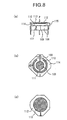
- Fig. 8 is a cross-sectional view, (a), and top views, (b) and (c), of a conventional pressure sensor of a capacitance detection type disclosed by, for example, Japanese Patent Application Laid-Open No. S60-56233.
- reference symbol 108 denotes a substrate which has an electrode 109 provided on the central section of an upper surface thereof, an electrode 110 for correction concentric to the both and provided on an edge section thereof and a penetrating hole 111 provided in the gap between the electrode 109 and the correction electrode 110.
- Reference symbol 112 denotes a diaphragm which has an electrode 113 which is provided on a surface thereof and which is opposed to the electrode 109.
- Reference symbol 114 denotes gap adjustment glass beads which are interposed between the substrate 108 and the diaphragm 112 so as to form a gap 115 between the electrodes 109 and 113.
- the pressure sensor when pressure P is applied to the diaphragm 112, the gap 115 in the central section becomes smaller and static capacitance increases between the electrodes 109 and 113.
- the pressure sensor is intended to measure the pressure using an almost univocal functional relationship held between this capacitance change and the pressure of a measurement target fluid.
- the conventional pressure sensor which is constituted as explained above, when the distortion gauge formed on the silicon substrate is used, it is impossible to secure sufficient bonding strength between the cylinder and the silicon substrate on which the distortion gauge is formed. It is, therefore, impossible to directly apply the pressure of the measurement target fluid to the silicon substrate and to measure the pressure of the measurement target fluid. Accordingly, it is required to cause pressure to be acted on a buffer in a different chamber using the diaphragm which is deformed by the measurement target fluid and to measure the pressure of the buffer using the distortion gauge provided on the silicon substrate.
- the distortion gauge of the silicon thin film provided on the metallic diaphragm when used, it is not easy to directly manufacture silicon thin film distortion gauges on the metallic diaphragm which receives the pressure in block in large quantities. This is because an apparatus for the silicon substrate (for silicon process) cannot be used as a diversion.
- the capacitance detection type pressure sensor it is necessary to form an insulating layer on the metallic diaphragm and to then form a capacitance detection electrode using the photo-engraving technique or the like.
- the metallic diaphragm when used, it is conventionally necessary to subject the metallic diaphragm to film formation processing, photo-engraving processing and the like.
- a film formation apparatus and a photo-engraving apparatus conventionally used for a silicon substrate cannot be used to carry out these processing.
- the silicon substrate is used, the structure of the pressure sensor is complicated, making it disadvantageously impossible to manufacture a highly reliable, inexpensive pressure sensor.
- the thermal pressure sensor thermally detects the displacement quantity of a diaphragm which receives pressure and measures a change in calorie following the deformation of the diaphragm and deprived of from the heating element of a detector or a section heated by the heating element which is away from the diaphragm by a fixed distance.
- this invention it is possible to manufacture measurement target elements on a silicon substrate in block in large quantities using a manufacturing technique and a manufacturing apparatus which are conventionally adapted to the silicon substrate.
- a metallic diaphragm provided on a cylinder is used as a pressure receiving member. It is an object of this invention to obtain a highly reliable, inexpensive pressure sensor which is not required to process the metallic diaphragm and provide a different chamber in which a buffer is held because an external force does not directly act on the measurement target element during pressure measurement.
- a pressure sensor in which it is constituted such that it includes a diaphragm structure having a first surface which receives pressure, and a first thermal detection section having a heating unit and arranged to be opposed to a central section of a second surface of the diaphragm structure, and which pressure sensor thermally detects a displacement quantity of the diaphragm caused by a pressure change by the first thermal detection section, wherein a second thermal detection section having a heating unit is provided, and at least a part of the second thermal detection section is arranged to be opposed to one of the diaphragm or a second diaphragm equal in structure to the diaphragm.
- the thermal detection section is provided to be opposed to the section of the diaphragm other than the center thereof which section is equal in film thickness to the central section of the second surface of the diaphragm to which the first thermal detection section is opposed to but which has a smaller displacement caused by pressure than that of the central section or to be opposed to the second diaphragm equal in structure to the above diaphragm.
- the first thermal detection section and the second thermal detection section are connected to constant-current sources, respectively to obtain a pressure signal output and a reference output having a smaller change according to pressure in order to obtain the difference between the signal output and the reference output. It is, therefore, possible to remove a noise component in the same phase or an offset drift component caused by a change in atmospheric temperature, and to thereby obtain an inexpensive, highly reliable pressure sensor.
- the second thermal detection section for reference output is arranged to be opposed to the second diaphragm which is equal in film thickness to the diaphragm, to which the first thermal detection section for pressure signal output is opposed, and which diaphragm does not receive pressure, and the difference between the signal output and the reference output is obtained. It is, therefore, possible to remove a noise component in the same phase or an offset drift component caused by a change in atmospheric temperature, and to thereby obtain an inexpensive, highly reliable pressure sensor.
- the second diaphragm equal in film thickness to the diaphragm to which the first thermal detection section for pressure signal output is opposed, and adjacent to the peripheral section of the diaphragm, is formed.
- the second thermal detection section for reference output is opposed to the second diaphragm and the difference between the signal output and the reference output is obtained. It is, therefore, possible to remove a noise component in the same phase or an offset drift component caused by a change in atmospheric temperature, and to thereby obtain an inexpensive, highly reliable pressure sensor.
- FIG. 6 is a cross-sectional view of a conventional pressure sensor which employs a silicon substrate on a pressure receiving surface and which has a distortion gauge formed on the silicon substrate;
- Fig. 7 is a cross-sectional view of a conventional pressure sensor which has a distortion gauge formed on a pressure receiving surface; and
- Fig. 8 is a cross-sectional view of a conventional capacitance type pressure sensor.
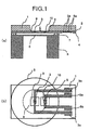
- Fig. 1 and 2 are views which explain a pressure sensor according to the first embodiment of the present invention.
- Fig. 1(a) is a cross-sectional typical view
- Fig. 1(b) is a plan, typical view
- Fig. 2 is a schematic block diagram of a read circuit.
- reference symbol 1 denotes a flat base material of a thermal sensor which is cut down from, for example, a silicon wafer
- 5 denotes a cylinder of, for example, SUS and a diaphragm 6 which receives pressure is formed.
- Reference symbol 2 denotes an insulating support film which is formed on one surface of the flat base material 1 and which is made of, for example, a silicon nitride film.
- a thermo-sensitive resistor film 3 is formed thereon. This thermo-sensitive resistor film corresponds to a heat emitting section which is used for heating resistance, temperature measurement resistance and relative resistance, which is made of, for example, platinum.
- a second thermo-sensitive resistor film 8 for reference output is formed.
- thermo-sensitive resistor film 3 is arranged to be opposite to the center of the diaphragm 6 whereas the second thermo-sensitive resistor film 8 is arranged to be opposite to the peripheral section of the diaphragm 6 which section has a smaller displacement relative to pressure.
- a protection film 4 is formed to cover the thermo-sensitive resistor films 3 and 8. Further, the silicon base material 1 around the thermo-sensitive resistor films 3 and 8 is removed and diaphragms 9 and 10 consisting of silicon nitride films 2 and 4 are formed so that heat generated in the thermo-sensitive resistor films 3 and 8 does not escape to the silicon base material 1 but flows in the SUS diaphragm 6 and the SUS cylinder 5 to be thereby efficiently utilized.
- thermo-sensitive resistor 3 for pressure measurement and the second thermo-sensitive resistor 8 for reference output are designed to have the same structure and the same resistance.
- a method of manufacturing principle parts of the pressure detector shown in Fig. 1 will next be explained.
- a silicon nitride film having a thickness of, for example, 1 ⁇ m is formed on a silicon wafer 1 which has a thickness of about 400 ⁇ m and which serves as the flat base material by a method such as a sputtering method, and the thermo-sensitive resistor film 3 which is made of platinum or the like and which has a thickness of, for example, 0.2 ⁇ m is formed thereon by a deposition method, the sputtering method or the like. Annealing is then performed for few hours at about 600 ⁇ for stabilization.
- This platinum film 3 is patterned by using a photo-engraving method, a wet etching method, a dry etching method or the like . As a result, current paths 3 and 8 having a pattern as shown in, for example, Fig. 1(b) are formed.
- a silicon nitride film which has a thickness of about 0.8 ⁇ m and which serves as the protection film 4, is formed on the platinum films 3, 8 and the silicon nitride film 2 by the sputtering method or the like.
- a spacer is formed. When the spacer is to be of an organic insulating film such as polyimide resin, it is formed by, for example, the following manner.
- the surface protection film 4 is formed first and a polyimide coating agent is then uniformly applied on the silicon substrate by a method such as spin-coating.
- a photosensitive resist is then applied and the polyimide resin is processed in a desired pattern by the photo-engraving technique.
- the pattern can be directly formed without using the resist, making the formation simpler.
- it is baked and solidified at about 300 ⁇ to be polyimide resin. In this way, when the polyimide coating agent is used, the spacer can be accurately formed by a simple process.
- thermo-engraving or the like and then is subjected to, for example, alkali etching.
- alkali etching a part of the flat base material 1 around the thermo-sensitive resistors 3 and 8 is removed, the diaphragms 9 and 10 consisting of the silicon nitride films 2 and 4 are formed and the first and second thermo-sensitive resistors are formed in different diaphragm structures.
- the pressure detector section of the pressure sensor of the present invention is formed on the silicon substrate using a so-called silicon technology as well as the film formation and photo-engraving technique.
- the detector section is not directly formed in the diaphragm 6 provided at the cylinder 5 and the pressure detector section and the cylinder 6 are connected to each other through the spacer.
- the following advantage can be, therefore, obtained. That is, thermal pressure detectors manufactured in block in large quantities on the silicon substrate are high in reliability and easily obtained at low cost. Furthermore, since no external force acts on the thermal pressure detector during the pressure measurement, high bonding strength is not required between the thermal pressure detector and the diaphragm, making it possible to be of a simple pressure sensor structure.
- a read circuit and the operation thereof will next be explained with reference to Figs. 1 and 2.
- a current is carried to the pressure measurement thermo-sensitive resistor (resistance R1) 3 and the reference output thermo-sensitive resistor (resistance R2) 8 from an external power supply (Vc) 30 and they are connected to constant-current sources 23 and 28, applied with constant currents and emit heat, respectively.
- a pressure signal voltage V1 and a reference output voltage V2 are generated in the connection sections of the constant-current sources 23 and 28, respectively.
- a differential amplifier 31 which obtains the difference between the pressure signal voltage V1 and the reference output voltage V2 and amplifies, is connected.
- the diaphragm 6 When the interior of the cylinder 5 receives pressure P from a fluid, the diaphragm 6 is displaced and approaches the the rmo-sensitive resistor 3, increasing heat flow to the diaphragm 6. As a result, the temperature of the pressure measurement thermo-sensitive resistor 3 decreases, the resistance R1 decreases and the pressure signal voltage V1 increases.
- the reference output thermo-sensitive resistor 8 since the reference output thermo-sensitive resistor 8 is formed at a position on the peripheral section of the diaphragm 6 which position has a smaller displacement by the pressure, even when the pressure is applied, a change in the resistance R2 is small. Namely, a change in the reference output voltage V2 is small.
- the resistance R1 also changes according to an atmospheric temperature.
- the first thermo-sensitive resistor 3 for pressure measurement and the second thermo-sensitive resistor 8 for reference output are designed to have the same structure and the same resistance and the resistances R1 and R2 have the same temperature dependency. Therefore, when the differential amplifier 31 which obtains the difference between the pressure signal voltage V1 and the reference output voltage V2 and amplifies is used, it is possible to remove an offset component which greatly changes according to temperature and to amplify and read a pressure signal component.
- the film thickness of the diaphragm 6 which is arranged opposite to the first thermo-sensitive resistor 3 for pressure measurement and the second thermo-sensitive resistor 8 for reference output is equal and thermal characteristic such as thermal resistance and thermal capacitance is equal.
- the resistances R1 and R2 have the same change characteristic according to time, therefore, it is possible to remove an offset component and to amplify and read a pressure signal component even when the atmospheric temperature makes sudden change.
- thermo-sensitive resistor 8 for reference output approaches close to the central section of the diaphragm 6, it is possible to make the difference in thermal characteristic with the first thermo-sensitive resistor 3 for pressure measurement smaller, thereby making it possible to remove the offset component more perfectly.
- Fig. 3 shows the relationship between the position of the second thermo-sensitive resistor 8 for reference output and sensor output when it is the diaphragm having a diameter of 4 mm.
- thermo-sensitive resistor 8 denotes such when R2 is arranged outside of the diaphragm (outside of the center thereof by not less than 2.0 mm), and (b) denotes such when the center of R2 is arranged at a position away from the center by 1.5 mm to be opposite thereto.
- thermo-sensitive resistor 8 is formed to be completely opposed to the thin film section of the diaphragm 6 at a position away from the center thereof by 1.5 mm so as to further improve the effect ((b) in Fig. 3), it is possible to obtain 84% sensitivity of when the thermo-sensitive resistor 8 is provided on the cylinder 5 outside of the diaphragm 6 ((a) in Fig. 3). It is seen that sensitivity deterioration caused by making the thermo-sensitive resistor 8 closer to the central section is small.
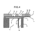
- Fig. 4 is a cross-sectional typical view of a pressure sensor according to a second embodiment of the present invention.
- the structure of the sensor and the principal constituent elements of a read circuit constitution are the same as those explained in the first embodiment with reference to Figs. 1 and 2.
- the second thermo-sensitive resistor for reference output is arranged to be closer to the central direction in which thefirstthermo-sensitiveresistorislocated. Therefore, the film thickness of the SUS opposed to the second thermo-sensitive resistor is equal to the film thickness of the central section thereof, to which the first thermo-sensitive resistor for pressure measurement is opposed.
- Fig. 4 is a cross-sectional typical view of a pressure sensor according to a second embodiment of the present invention.
- the structure of the sensor and the principal constituent elements of a read circuit constitution are the same as those explained in the first embodiment with reference to Figs. 1 and 2.
- the second thermo-sensitive resistor for reference output is arranged to be closer to the central direction in which thefirstthermo-sensitiveresistoris
- a second chamber 12 and a diaphragm 16 which do not receive pressure are provided inside of an SUS cylinder to which a thermo-sensitive resistor 8 for reference output is opposed.
- This second SUS diaphragm 16 is processed to have the same film thickness as that of the central section of a first diaphragm 6.
- the second SUS diaphragm to which the thermo-sensitive resistor for reference output is opposed is not displaced by pressure and no sensitivity deterioration occurs.
- the film thickness of the SUS to which the second thermo-sensitive resistor for reference output is opposed is constituted to be equal to that of the central section of the diaphragm to which the thermo-sensitive resistor for pressure measurement is opposed. Therefore, the thermal resistance characteristic of the thermo-sensitive resistor for reference output is almost equal to that of the thermo-sensitive resistor for pressure measurement.
- the signal output sensitivity and offset are not drifted even by a sudden change in atmospheric temperature, making it possible to obtain an accurate pressure signal output.
- Fig. 5 is a typical view of a pressure sensor according to a third embodiment of the present invention.
- Fig. 5(a) is a cross-sectional typical view of the pressure sensor and
- Fig. 5(b) is a plan view thereof.
- the structure of the sensor and the principal constituent elements of a read circuit constitution are the same as those explained in the first embodiment with reference to Figs. 1 and 2.
- a second small diaphragm 16 is provided in a section to which a second thermo-sensitive resistor 8 for reference output is opposed.
- This second SUS diaphragm 16 is formed in the first chamber 11 in which a first diaphragm 6 is formed and it receives the same pressure as that of the first diaphragm 6.
- the diameter of the diaphragm is set small, it is possible to make the displacement quantity relative to the pressure negligibly small.
- the second SUS diaphragm to which the second thermo-sensitive resistor for reference output is opposed is not displaced by pressure and no sensitivity deterioration occurs.
- the film thickness of the second SUS to which the second thermo-sensitive resistor for reference output is opposed has the same structure (film thickness and material quality) as that of the diaphragm central section to which the first thermo-sensitive resistor for pressure measurement is opposed. It is, therefore, possible to make the thermal resistance characteristic of the second thermo-sensitive resistor for reference output almost equal to that of the first thermo-sensitive resistor for pressure measurement.
- the signal output sensitivity and offset are not drifted even by a sudden change in atmospheric temperature, making it possible to obtain an accurate pressure signal output.
- the pressure sensor according to this invention is a pressure sensor for, for example, a detection of the oil pressure of a vehicle brake, a detection of fuel pressure for engine control, a detection of oil pressure for transmission, a detection of the coolant pressure of an air conditioner and that of a refrigerator.
Landscapes
- Physics & Mathematics (AREA)
- General Physics & Mathematics (AREA)
- Measuring Fluid Pressure (AREA)
Abstract
A pressure sensor of this invention is a pressure
sensor which includes a diaphragm 6 having a first surface
receiving pressure, a first thermal detection section 3
arranged to be opposed to a central section of the diaphragm
through a spacer 7 and having a thermo-sensitive resistance
section, and a second thermal detection section 8 having
a small or no displacement by pressure, arranged on and
opposed to the diaphragm and having a thermo-sensitive
resistance section, and which pressure sensor amplifies
and outputs a difference between the first thermal
detection section for pressure measurement and the second
thermal detection section for reference output. Since the
diaphragm to which the second thermal detection section
8 is opposed is set equal in film thickness to the diaphragm
to which the first thermal detection section 3 is opposed,
it is possible to obtain a pressure sensor which can
accurately measure pressure with a small output change
relative to a sudden change in atmospheric temperature.
It is unnecessary to subject a surface of the diaphragm
which directly receives pressure from a measurement target
fluid to processing such as film formation and
photo-engraving. Therefore, it is possible to manufacture
important sections of a thermal pressure detector in block
in large quantities on a silicon substrate at simple
manufacturing steps and to obtain an inexpensive pressure
sensor having the thermal pressure detector with improved
accuracy and reliability.
Description
This invention relates to a pressure sensor which
measures pressure. More Particularly, this invention
relates to a pressure sensor which measures calorie deprived
of from a heating element included in a thermal pressure
detector or a section heated by the heating element by a
diaphragm which is arranged to be opposite to and away from
the heating element or the heated section by a fixed distance,
by using the thermal pressure detector.
Apressure sensor which measures the flexible quantity
of a diaphragm using an almost univocal functional
relationship held between the pressure of a measurement
target fluid and the flexible quantity of the diaphragm on
a cylinder which diaphragm receives pressure from the
measurement target fluid and using a distortion gauge which
is formed on the diaphragm by a film formation technique,
a photo-engraving technique or the like, and which sensor
thereby obtains the pressure of the fluid proportional to
the flexible quantity of the diaphragm, is widely utilized
for the detection of the quantity of the intake air of an
internal combustion engine, that of the oil pressure of a
vehicle brake or the like.
Fig. 6 is a cross-sectional view of a conventional
pressure sensor which is disclosed by, for example, Japanese
Utility Model Application Laid-Open No. S61-137242
(microfilm of Japanese Utility Model Application No.
S60-19572).
In Fig. 6, a reference symbol 101 denotes a metallic
cylinder, 102 denotes a semiconductor monocrystalline plate
which is provided with a distortion gauge 103 and the
semiconductor monocrystalline plate consists of, for
example, a silicon substrate. For the pressure sensor in
which the semiconductor monocrystalline plate 102 is bonded
to the metallic cylinder 101 shown in Fig. 6, the metallic
cylinder 101 and the semiconductor monocrystalline plate
102 differ in material and a distortion, therefore, tends
to occur to the semiconductormonocrystalline plate 102 which
constitutes a diaphragm due to the difference in the
coefficient of linear expansion between the cylinder 101
and the plate 102 at a time when temperature change. This
causes a measurement error. In addition, since the pressure
of a measurement target fluid is directly applied to the
semiconductor monocrystalline plate 102, it is necessary
to secure sufficiently high bonding strength between the
metallic cylinder 101 and the semiconductor monocrystalline
plate 102.
In Fig. 7, a reference symbol 104 denotes a metallic
cylinder which consists of a cut-off pipe such as a stainless
pipe. A metallic thin film 105 which is welded to the
cylinder 104 is formed out of a thin plate of a rolled material
and it has a uniform film thickness and a flat surface because
of the rolled material. The material of the metallic thin
film 105 is the same as that of the cylinder 104. In addition,
a silicon oxide thin film 106 which functions as an insulating
film, is formed on the upper surface of the metallic thin
film 105. A plasma CVD method is used to form the silicon
oxide thin film 106. A silicon thin film which constitutes
a distortion gauge 107 is then formed on the silicon oxide
thin film by the plasma CVD method. This silicon thin film
is etched to partially leave the silicon thin film and remove
the other sections as shown in Fig. 7, and the distortion
gauge 107 is formed out of the silicon thin film which is
thus left. Furthermore, metal such as gold is deposited
on the distortion gauge 107 to thereby form an electrode.
A lead wire is bonded to this electrode by ultrasonic bonding.
The electrode and the lead wire are appropriately connected
to each other, whereby a circuit can be formed.
Each of the conventional pressure sensors shown in
Figs. 6 and 7 uses the distortion gauge. The diaphragm is
distorted by the pressure of the measurement target fluid
applied to the diaphragm and each of these pressure sensors
measures the distortion by the distortion gauge provided
on the diaphragm. Besides these pressure sensors, a
pressure sensor which detects the flexure of a diaphragm
as a capacitance change is also used.
Fig. 8 is a cross-sectional view, (a), and top views,
(b) and (c), of a conventional pressure sensor of a
capacitance detection type disclosed by, for example,
Japanese Patent Application Laid-Open No. S60-56233.
In Fig. 8, reference symbol 108 denotes a substrate
which has an electrode 109 provided on the central section
of an upper surface thereof, an electrode 110 for correction
concentric to the both and provided on an edge section thereof
and a penetrating hole 111 provided in the gap between the
electrode 109 and the correction electrode 110. Reference
symbol 112 denotes a diaphragm which has an electrode 113
which is provided on a surface thereof and which is opposed
to the electrode 109. Reference symbol 114 denotes gap
adjustment glass beads which are interposed between the
substrate 108 and the diaphragm 112 so as to form a gap 115
between the electrodes 109 and 113. In this pressure sensor,
when pressure P is applied to the diaphragm 112, the gap
115 in the central section becomes smaller and static
capacitance increases between the electrodes 109 and 113.
The pressure sensor is intended to measure the pressure using
an almost univocal functional relationship held between this
capacitance change and the pressure of a measurement target
fluid.
According to the conventional pressure sensor which
is constituted as explained above, when the distortion gauge
formed on the silicon substrate is used, it is impossible
to secure sufficient bonding strength between the cylinder
and the silicon substrate on which the distortion gauge is
formed. It is, therefore, impossible to directly apply the
pressure of the measurement target fluid to the silicon
substrate and to measure the pressure of the measurement
target fluid. Accordingly, it is required to cause pressure
to be acted on a buffer in a different chamber using the
diaphragm which is deformed by the measurement target fluid
and to measure the pressure of the buffer using the distortion
gauge provided on the silicon substrate.
Further, when the distortion gauge of the silicon thin
film provided on the metallic diaphragm is used, it is not
easy to directly manufacture silicon thin film distortion
gauges on the metallic diaphragm which receives the pressure
in block in large quantities. This is because an apparatus
for the silicon substrate (for silicon process) cannot be
used as a diversion.
Moreover, according to the capacitance detection type
pressure sensor, it is necessary to form an insulating layer
on the metallic diaphragm and to then form a capacitance
detection electrode using the photo-engraving technique or
the like. As can be seen, when the metallic diaphragm is
used, it is conventionally necessary to subject the metallic
diaphragm to film formation processing, photo-engraving
processing and the like. However, a film formation
apparatus and a photo-engraving apparatus conventionally
used for a silicon substrate cannot be used to carry out
these processing. Besides, when the silicon substrate is
used, the structure of the pressure sensor is complicated,
making it disadvantageously impossible to manufacture a
highly reliable, inexpensive pressure sensor.
This invention has been achieved to solve the
above-explained conventional disadvantages. It is an
object of this invention to provide a simple thermal pressure
sensor. The thermal pressure sensor thermally detects the
displacement quantity of a diaphragm which receives pressure
and measures a change in calorie following the deformation
of the diaphragm and deprived of from the heating element
of a detector or a section heated by the heating element
which is away from the diaphragm by a fixed distance.
According to this invention, it is possible to
manufacture measurement target elements on a silicon
substrate in block in large quantities using a manufacturing
technique and a manufacturing apparatus which are
conventionally adapted to the silicon substrate. A
metallic diaphragm provided on a cylinder is used as a
pressure receiving member. It is an object of this invention
to obtain a highly reliable, inexpensive pressure sensor
which is not required to process the metallic diaphragm and
provide a different chamber in which a buffer is held because
an external force does not directly act on the measurement
target element during pressure measurement.
According to one aspect of the invention, there is
provided a pressure sensor in which it is constituted such
that it includes a diaphragm structure having a first surface
which receives pressure, and a first thermal detection
section having a heating unit and arranged to be opposed
to a central section of a second surface of the diaphragm
structure, and which pressure sensor thermally detects a
displacement quantity of the diaphragm caused by a pressure
change by the first thermal detection section, wherein a
second thermal detection section having a heating unit is
provided, and at least a part of the second thermal detection
section is arranged to be opposed to one of the diaphragm
or a second diaphragm equal in structure to the diaphragm.
This makes it unnecessary to subject a diaphragm surface
which receives the pressure to processing such as film
formation and photo-engraving. It is, therefore, possible
to manufacture principle parts of a thermal pressure detector
in block and in large quantities on a silicon substrate at
simple manufacturing steps, to improve the accuracy and
reliability of the thermal pressure detector, and to obtain
an inexpensive pressure sensor. In addition, the pressure
sensor thermally measures the pressure in a non-contact
manner. Therefore, an external force does not directly act
on the thermal pressure detector during measurement. Thus,
it is unnecessary to secure sufficient bonding strength to
resist the pressure of a measurement target fluid between
a cylinder and the thermal pressure detector. It is possible
to be of a simple structure and to obtain an inexpensive
pressure sensor. Furthermore, the thermal detection
section is provided to be opposed to the section of the
diaphragm other than the center thereof which section is
equal in film thickness to the central section of the second
surface of the diaphragm to which the first thermal detection
section is opposed to but which has a smaller displacement
caused by pressure than that of the central section or to
be opposed to the second diaphragm equal in structure to
the above diaphragm. The first thermal detection section
and the second thermal detection section are connected to
constant-current sources, respectively to obtain a pressure
signal output and a reference output having a smaller change
according to pressure in order to obtain the difference
between the signal output and the reference output. It is,
therefore, possible to remove a noise component in the same
phase or an offset drift component caused by a change in
atmospheric temperature, and to thereby obtain an
inexpensive, highly reliable pressure sensor.
In addition, the second thermal detection section for
reference output is arranged to be opposed to the second
diaphragm which is equal in film thickness to the diaphragm,
to which the first thermal detection section for pressure
signal output is opposed, and which diaphragm does not
receive pressure, and the difference between the signal
output and the reference output is obtained. It is,
therefore, possible to remove a noise component in the same
phase or an offset drift component caused by a change in
atmospheric temperature, and to thereby obtain an
inexpensive, highly reliable pressure sensor.
Moreover, the second diaphragm equal in film thickness
to the diaphragm to which the first thermal detection section
for pressure signal output is opposed, and adjacent to the
peripheral section of the diaphragm, is formed. The second
thermal detection section for reference output is opposed
to the second diaphragm and the difference between the signal
output and the reference output is obtained. It is,
therefore, possible to remove a noise component in the same
phase or an offset drift component caused by a change in
atmospheric temperature, and to thereby obtain an
inexpensive, highly reliable pressure sensor.
Fig. 1 is a typical view of a pressure sensor according
to a first embodiment of the present invention, i.e., Fig.
1(a) in is a cross-sectional typical view; Fig. 1(b) is a
plan view thereof; Fig. 2 is a schematic block diagram of
a signal read circuit; Fig. 3 is a graph which shows the
relationship between the position of a thermal detection
section and characteristic thereof; Fig. 4 is a
cross-sectional typical view of a pressure sensor according
to a second embodiment of the present invention; Fig. 5 is
a typical view of a pressure sensor according to a third
embodiment of the present invention, i.e., (a) is a
cross-sectional typical view and (b) is a plan view thereof;
Fig. 6 is a cross-sectional view of a conventional pressure
sensor which employs a silicon substrate on a pressure
receiving surface and which has a distortion gauge formed
on the silicon substrate; Fig. 7 is a cross-sectional view
of a conventional pressure sensor which has a distortion
gauge formed on a pressure receiving surface; and Fig. 8
is a cross-sectional view of a conventional capacitance type pressure sensor.
The embodiments of this invention will be explained
hereinafter with reference to the drawings.
Fig. 1 and 2 are views which explain a pressure sensor
according to the first embodiment of the present invention.
Fig. 1(a) is a cross-sectional typical view, Fig. 1(b) is
a plan, typical view, and Fig. 2 is a schematic block diagram
of a read circuit.
In Figs. 1 and 2, reference symbol 1 denotes a flat
base material of a thermal sensor which is cut down from,
for example, a silicon wafer, 5 denotes a cylinder of, for
example, SUS and a diaphragm 6 which receives pressure is
formed. Reference symbol 2 denotes an insulating support
film which is formed on one surface of the flat base material
1 and which is made of, for example, a silicon nitride film.
A thermo-sensitive resistor film 3 is formed thereon. This
thermo-sensitive resistor film corresponds to a heat
emitting section which is used for heating resistance,
temperature measurement resistance and relative resistance,
which is made of, for example, platinum. In addition, a
second thermo-sensitive resistor film 8 for reference output
is formed. The thermo-sensitive resistor film 3 is arranged
to be opposite to the center of the diaphragm 6 whereas the
second thermo-sensitive resistor film 8 is arranged to be
opposite to the peripheral section of the diaphragm 6 which
section has a smaller displacement relative to pressure.
A protection film 4 is formed to cover the thermo- sensitive
resistor films 3 and 8. Further, the silicon base material
1 around the thermo- sensitive resistor films 3 and 8 is
removed and diaphragms 9 and 10 consisting of silicon nitride
films 2 and 4 are formed so that heat generated in the
thermo- sensitive resistor films 3 and 8 does not escape to
the silicon base material 1 but flows in the SUS diaphragm
6 and the SUS cylinder 5 to be thereby efficiently utilized.
Further, a spacer 7 is provided so that the diaphragm 6 is
arranged to be opposite to the measurement sections of the
thermo- sensitive resistor films 3 and 8 and away therefrom
by a predetermined distance. Reference symbols 3a and 8a
denote pad sections (wiring takeoffs) of the
thermo- sensitive resistor films 3 and 8, respectively. The
first thermo-sensitive resistor 3 for pressure measurement
and the second thermo-sensitive resistor 8 for reference
output are designed to have the same structure and the same
resistance.
A method of manufacturing principle parts of the
pressure detector shown in Fig. 1 will next be explained.
A silicon nitride film having a thickness of, for example,
1 □m is formed on a silicon wafer 1 which has a thickness
of about 400 □m and which serves as the flat base material
by a method such as a sputtering method, and the
thermo-sensitive resistor film 3 which is made of platinum
or the like and which has a thickness of, for example, 0.2
□m is formed thereon by a deposition method, the sputtering
method or the like. Annealing is then performed for few
hours at about 600□ for stabilization. This platinum film
3 is patterned by using a photo-engraving method, a wet
etching method, a dry etching method or the like . As a result,
current paths 3 and 8 having a pattern as shown in, for example,
Fig. 1(b) are formed. A silicon nitride film which has a
thickness of about 0.8 □m and which serves as the protection
film 4, is formed on the platinum films 3, 8 and the silicon
nitride film 2 by the sputtering method or the like. After
forming the surface protection film 4, a spacer is formed.
When the spacer is to be of an organic insulating film such
as polyimide resin, it is formed by, for example, the
following manner. The surface protection film 4 is formed
first and a polyimide coating agent is then uniformly applied
on the silicon substrate by a method such as spin-coating.
A photosensitive resist is then applied and the polyimide
resin is processed in a desired pattern by the
photo-engraving technique. When a photosensitive
polyimide coating agent is used, the pattern can be directly
formed without using the resist, making the formation simpler.
After being pattern processed, it is baked and solidified
at about 300□ to be polyimide resin. In this way, when the
polyimide coating agent is used, the spacer can be accurately
formed by a simple process. Finally, desired patterning
is conducted to the surface of the flat base material 1
opposite to the surface on which the support film 2 is arranged,
by the photo-engraving or the like and then is subjected
to, for example, alkali etching. By doing so, a part of
the flat base material 1 around the thermo- sensitive
resistors 3 and 8 is removed, the diaphragms 9 and 10
consisting of the silicon nitride films 2 and 4 are formed
and the first and second thermo-sensitive resistors are
formed in different diaphragm structures. As can be seen,
the pressure detector section of the pressure sensor of the
present invention is formed on the silicon substrate using
a so-called silicon technology as well as the film formation
and photo-engraving technique. The detector section is not
directly formed in the diaphragm 6 provided at the cylinder
5 and the pressure detector section and the cylinder 6 are
connected to each other through the spacer. The following
advantage can be, therefore, obtained. That is, thermal
pressure detectors manufactured in block in large quantities
on the silicon substrate are high in reliability and easily
obtained at low cost. Furthermore, since no external force
acts on the thermal pressure detector during the pressure
measurement, high bonding strength is not required between
the thermal pressure detector and the diaphragm, making it
possible to be of a simple pressure sensor structure.
A read circuit and the operation thereof will next be explained with reference to Figs. 1 and 2. A current is carried to the pressure measurement thermo-sensitive resistor (resistance R1) 3 and the reference output
thermo-sensitive resistor (resistance R2) 8 from an external
power supply (Vc) 30 and they are connected to
constant- current sources 23 and 28, applied with constant
currents and emit heat, respectively. A pressure signal
voltage V1 and a reference output voltage V2 are generated
in the connection sections of the constant- current sources
23 and 28, respectively. A differential amplifier 31 which
obtains the difference between the pressure signal voltage
V1 and the reference output voltage V2 and amplifies, is
connected. When the interior of the cylinder 5 receives
pressure P from a fluid, the diaphragm 6 is displaced and
approaches the the rmo-sensitive resistor 3, increasing heat
flow to the diaphragm 6. As a result, the temperature of
the pressure measurement thermo-sensitive resistor 3
decreases, the resistance R1 decreases and the pressure
signal voltage V1 increases. On the other hand, since the
reference output thermo-sensitive resistor 8 is formed at
a position on the peripheral section of the diaphragm 6 which
position has a smaller displacement by the pressure, even
when the pressure is applied, a change in the resistance
R2 is small. Namely, a change in the reference output voltage
V2 is small. The resistance R1 also changes according to
an atmospheric temperature. Therefore, when the
atmospheric temperature changes, the pressure signal
voltage V1 changes greatly. However, the first
thermo-sensitive resistor 3 for pressure measurement and
the second thermo-sensitive resistor 8 for reference output
are designed to have the same structure and the same
resistance and the resistances R1 and R2 have the same
temperature dependency. Therefore, when the differential
amplifier 31 which obtains the difference between the
pressure signal voltage V1 and the reference output voltage
V2 and amplifies is used, it is possible to remove an offset
component which greatly changes according to temperature
and to amplify and read a pressure signal component. In
addition, the film thickness of the diaphragm 6 which is
arranged opposite to the first thermo-sensitive resistor
3 for pressure measurement and the second thermo-sensitive
resistor 8 for reference output is equal and thermal
characteristic such as thermal resistance and thermal
capacitance is equal. Therefore, a change in heat flow to
the diaphragm according to time is equal. The resistances
R1 and R2 have the same change characteristic according to
time, therefore, it is possible to remove an offset component
and to amplify and read a pressure signal component even
when the atmospheric temperature makes sudden change.
As the position of the second thermo-sensitive
resistor 8 for reference output approaches close to the
central section of the diaphragm 6, it is possible to make
the difference in thermal characteristic with the first
thermo-sensitive resistor 3 for pressure measurement
smaller, thereby making it possible to remove the offset
component more perfectly. However, since the difference
in diaphragm displacement quantity between the pressure
measurement section and the reference output section becomes
smaller, sensitivity is deteriorated. Fig. 3 shows the
relationship between the position of the second
thermo-sensitive resistor 8 for reference output and sensor
output when it is the diaphragm having a diameter of 4 mm.
In Fig. 3, (a) denotes such when R2 is arranged outside of
the diaphragm (outside of the center thereof by not less
than 2.0 mm), and (b) denotes such when the center of R2
is arranged at a position away from the center by 1.5 mm
to be opposite thereto. When at least a part of the second
thermo-sensitive resistor 8 is opposed to the thin film
section of the diaphragm 6, heat is carried not only to the
cylinder 5 but also to the diaphragm 6 and it is, therefore,
possible to obtain the effect that the thermal characteristic
is made closer. Further, even when the thermo-sensitive
resistor 8 is formed to be completely opposed to the thin
film section of the diaphragm 6 at a position away from the
center thereof by 1.5 mm so as to further improve the effect
((b) in Fig. 3), it is possible to obtain 84% sensitivity
of when the thermo-sensitive resistor 8 is provided on the
cylinder 5 outside of the diaphragm 6 ((a) in Fig. 3). It
is seen that sensitivity deterioration caused by making the
thermo-sensitive resistor 8 closer to the central section
is small.
The second embodiment of the present invention will
be explained hereinafter with reference to the drawings.
Fig. 4 is a cross-sectional typical view of a pressure sensor
according to a second embodiment of the present invention.
In Fig. 4, the structure of the sensor and the principal
constituent elements of a read circuit constitution are the
same as those explained in the first embodiment with
reference to Figs. 1 and 2. In Fig. 1 of the first embodiment,
the second thermo-sensitive resistor for reference output
is arranged to be closer to the central direction in which
thefirstthermo-sensitiveresistorislocated. Therefore,
the film thickness of the SUS opposed to the second
thermo-sensitive resistor is equal to the film thickness
of the central section thereof, to which the first
thermo-sensitive resistor for pressure measurement is
opposed. In this embodiment shown in Fig. 4, a second chamber
12 and a diaphragm 16 which do not receive pressure are
provided inside of an SUS cylinder to which a
thermo-sensitive resistor 8 for reference output is opposed.
This second SUS diaphragm 16 is processed to have the same
film thickness as that of the central section of a first
diaphragm 6.
According to the second embodiment, the second SUS
diaphragm to which the thermo-sensitive resistor for
reference output is opposed, is not displaced by pressure
and no sensitivity deterioration occurs. In addition, the
film thickness of the SUS to which the second
thermo-sensitive resistor for reference output is opposed,
is constituted to be equal to that of the central section
of the diaphragm to which the thermo-sensitive resistor for
pressure measurement is opposed. Therefore, the thermal
resistance characteristic of the thermo-sensitive resistor
for reference output is almost equal to that of the
thermo-sensitive resistor for pressure measurement. Thus,
the signal output sensitivity and offset are not drifted
even by a sudden change in atmospheric temperature, making
it possible to obtain an accurate pressure signal output.
The third embodiment of the present invention will
be explained hereinafter with reference to the drawings.
Fig. 5 is a typical view of a pressure sensor according to
a third embodiment of the present invention. Fig. 5(a) is
a cross-sectional typical view of the pressure sensor and
Fig. 5(b) is a plan view thereof. In Fig. 5, the structure
of the sensor and the principal constituent elements of a
read circuit constitution are the same as those explained
in the first embodiment with reference to Figs. 1 and 2.
In the third embodiment, as shown in Fig. 5, a second small
diaphragm 16 is provided in a section to which a second
thermo-sensitive resistor 8 for reference output is opposed.
This second SUS diaphragm 16 is formed in the first chamber
11 in which a first diaphragm 6 is formed and it receives
the same pressure as that of the first diaphragm 6. However,
when the diameter of the diaphragm is set small, it is possible
to make the displacement quantity relative to the pressure
negligibly small.
According to the third embodiment, the second SUS
diaphragm to which the second thermo-sensitive resistor for
reference output is opposed, is not displaced by pressure
and no sensitivity deterioration occurs. In addition, the
film thickness of the second SUS to which the second
thermo-sensitive resistor for reference output is opposed,
has the same structure (film thickness and material quality)
as that of the diaphragm central section to which the first
thermo-sensitive resistor for pressure measurement is
opposed. It is, therefore, possible to make the thermal
resistance characteristic of the second thermo-sensitive
resistor for reference output almost equal to that of the
first thermo-sensitive resistor for pressure measurement.
Thus, the signal output sensitivity and offset are not
drifted even by a sudden change in atmospheric temperature,
making it possible to obtain an accurate pressure signal
output.
The pressure sensor according to this invention is
a pressure sensor for, for example, a detection of the oil
pressure of a vehicle brake, a detection of fuel pressure
for engine control, a detection of oil pressure for
transmission, a detection of the coolant pressure of an air
conditioner and that of a refrigerator.
Claims (3)
- A pressure sensor comprising:a diaphragm structure having at least one diaphragm (6), the diaphragm (6) having first and second surfaces, the first surface of the diaphragm (6) receiving pressure;a first thermal detection unit (3) having a heating unit and arranged to be opposed to a central section of the second surface of the diaphragm (6), the first thermal detection unit (3) detecting an amount of displacement of the diaphragm (6) caused by a pressure change based on thermal detection;a second thermal detection unit (8) having a heating unit, wherein at least a part of the second thermal detection unit (8) is arranged to be opposed to either the diaphragm (6) or another diaphragm (16) having the same structure as the diaphragm (6).
- The pressure sensor as claimed in claim 1, wherein the another diaphragm (16) that does not receive the pressure and at least a part of the second thermal detection unit (8) is opposed to the another diaphragm (16), and the diaphragm (6) and the another diaphragm (16) have equal film thickness.
- The pressure sensor as claimed in claim 1, wherein at least a part of the second thermal detection unit (8) is opposed to the another diaphragm (16), the diaphragm (6) and the another diaphragm (16) have equal film thickness, and the another diaphragm (16) has smaller area than the diaphragm (6).
Applications Claiming Priority (1)
| Application Number | Priority Date | Filing Date | Title |
|---|---|---|---|
| PCT/JP2000/005124 WO2002010703A1 (en) | 2000-07-31 | 2000-07-31 | Pressure sensor |
Publications (2)
| Publication Number | Publication Date |
|---|---|
| EP1306655A1 true EP1306655A1 (en) | 2003-05-02 |
| EP1306655A4 EP1306655A4 (en) | 2006-02-22 |
Family
ID=11736314
Family Applications (1)
| Application Number | Title | Priority Date | Filing Date |
|---|---|---|---|
| EP00948332A Withdrawn EP1306655A4 (en) | 2000-07-31 | 2000-07-31 | MANOM TRIQUE PROBE |
Country Status (4)
| Country | Link |
|---|---|
| US (1) | US6619130B1 (en) |
| EP (1) | EP1306655A4 (en) |
| KR (1) | KR20020087121A (en) |
| WO (1) | WO2002010703A1 (en) |
Families Citing this family (6)
| Publication number | Priority date | Publication date | Assignee | Title |
|---|---|---|---|---|
| US7216498B2 (en) * | 2003-09-25 | 2007-05-15 | Tecumseh Products Company | Method and apparatus for determining supercritical pressure in a heat exchanger |
| DE10360079A1 (en) * | 2003-12-20 | 2005-07-21 | Robert Bosch Gmbh | Pressure transducer |
| US7863495B2 (en) * | 2006-01-12 | 2011-01-04 | Aalnex, Inc. | Dressing substrate |
| PL2784462T3 (en) * | 2013-03-27 | 2015-06-30 | Grieshaber Vega Kg | Capacitative pressure measurement cell for detecting the pressure of a medium adjacent to the measurement cell |
| JP7737144B2 (en) * | 2022-01-24 | 2025-09-10 | 株式会社ブイ・テクノロジー | Tension measuring device and tension measuring method |
| WO2025056480A1 (en) | 2023-09-11 | 2025-03-20 | Hahn-Schickard-Gesellschaft für angewandte Forschung e.V. | Thermal pressure sensor for measuring a pressure of a fluid |
Family Cites Families (12)
| Publication number | Priority date | Publication date | Assignee | Title |
|---|---|---|---|---|
| US4320664A (en) | 1980-02-25 | 1982-03-23 | Texas Instruments Incorporated | Thermally compensated silicon pressure sensor |
| JPS5872059A (en) | 1981-10-09 | 1983-04-28 | ハネウエル・インコ−ポレ−テツド | Semiconductor device and its manufacture |
| JPS6056233A (en) | 1983-09-08 | 1985-04-01 | Matsushita Electric Ind Co Ltd | Pressure sensor unit |
| JPS61137242A (en) | 1984-12-07 | 1986-06-24 | Matsushita Electric Ind Co Ltd | Optical disc and address recording/playback method |
| US4682503A (en) * | 1986-05-16 | 1987-07-28 | Honeywell Inc. | Microscopic size, thermal conductivity type, air or gas absolute pressure sensor |
| US5187674A (en) | 1989-12-28 | 1993-02-16 | Honeywell Inc. | Versatile, overpressure proof, absolute pressure sensor |
| JPH0510840A (en) | 1991-07-01 | 1993-01-19 | Nagano Keiki Seisakusho Ltd | Differential pressure detecting device |
| JPH0510839A (en) * | 1991-07-02 | 1993-01-19 | Yokogawa Electric Corp | Semiconductor pressure sensor |
| JP3124857B2 (en) | 1993-02-22 | 2001-01-15 | 松下電工株式会社 | Vacuum measurement sensor |
| JPH08184514A (en) | 1994-12-27 | 1996-07-16 | New Japan Radio Co Ltd | Pressure sensor |
| JP2000146734A (en) * | 1998-11-13 | 2000-05-26 | Matsushita Electric Works Ltd | Semiconductor pressure sensor and its junction surface inspection method |
| EP1059517A4 (en) | 1998-12-24 | 2002-03-06 | Mitsubishi Electric Corp | PRESSURE DETECTOR |
-
2000
- 2000-07-31 KR KR1020027013256A patent/KR20020087121A/en not_active Abandoned
- 2000-07-31 US US10/148,809 patent/US6619130B1/en not_active Expired - Lifetime
- 2000-07-31 WO PCT/JP2000/005124 patent/WO2002010703A1/en not_active Ceased
- 2000-07-31 EP EP00948332A patent/EP1306655A4/en not_active Withdrawn
Also Published As
| Publication number | Publication date |
|---|---|
| EP1306655A4 (en) | 2006-02-22 |
| WO2002010703A1 (en) | 2002-02-07 |
| KR20020087121A (en) | 2002-11-21 |
| US6619130B1 (en) | 2003-09-16 |
Similar Documents
| Publication | Publication Date | Title |
|---|---|---|
| JP4307738B2 (en) | Pressure sensor | |
| KR960015065B1 (en) | Control and detection circuitry for mass air-flow sensors | |
| US4888988A (en) | Silicon based mass airflow sensor and its fabrication method | |
| US6209402B1 (en) | Measuring element, mass air flow meter therewith and compensating method for accurately measuring air flow | |
| CN101308036B (en) | Thermal flowmeter | |
| JPWO2000039551A1 (en) | Pressure Sensor | |
| US6973836B2 (en) | Semiconductor pressure sensor having diaphragm | |
| CN102004125B (en) | Thermal humidity sensor | |
| JP3455473B2 (en) | Thermal flow sensor | |
| JP4608843B2 (en) | Flow measuring device | |
| US6470742B1 (en) | Flow sensor | |
| JP4157034B2 (en) | Thermal flow meter | |
| JPH0989619A (en) | Thermal flow meter | |
| JP3513048B2 (en) | Thermal flow sensor and method of manufacturing the same | |
| US6591683B1 (en) | Pressure sensor | |
| JP2001272293A (en) | Pressure sensor | |
| EP1870681B1 (en) | Thermal type flow rate measuring apparatus | |
| US6619130B1 (en) | Pressure sensor | |
| GB2251312A (en) | Sensor for measuring fluid flow rate | |
| JPH08110317A (en) | Integrated microsensor | |
| JPH0972805A (en) | Semiconductor sensor | |
| JPH11148849A (en) | Fluid detection sensor | |
| CN116314420B (en) | An infrared detector with integrated temperature monitoring structure | |
| JPWO2002010703A1 (en) | Pressure Sensor | |
| KR0184803B1 (en) | Heating element for automobile air conditioning and manufacturing method |
Legal Events
| Date | Code | Title | Description |
|---|---|---|---|
| PUAI | Public reference made under article 153(3) epc to a published international application that has entered the european phase |
Free format text: ORIGINAL CODE: 0009012 |
|
| 17P | Request for examination filed |
Effective date: 20020718 |
|
| AK | Designated contracting states |
Designated state(s): AT BE CH CY DE DK ES FI FR GB GR IE IT LI LU MC NL PT SE |
|
| RBV | Designated contracting states (corrected) |
Designated state(s): AT BE DE FR |
|
| A4 | Supplementary search report drawn up and despatched |
Effective date: 20060109 |
|
| RAP1 | Party data changed (applicant data changed or rights of an application transferred) |
Owner name: MITSUBISHI DENKI KABUSHIKI KAISHA |
|
| STAA | Information on the status of an ep patent application or granted ep patent |
Free format text: STATUS: THE APPLICATION IS DEEMED TO BE WITHDRAWN |
|
| 18D | Application deemed to be withdrawn |
Effective date: 20060509 |