EP1306519A2 - Wear-resistant, variable diameter expansion tool and expansion methods - Google Patents
Wear-resistant, variable diameter expansion tool and expansion methods Download PDFInfo
- Publication number
- EP1306519A2 EP1306519A2 EP02257321A EP02257321A EP1306519A2 EP 1306519 A2 EP1306519 A2 EP 1306519A2 EP 02257321 A EP02257321 A EP 02257321A EP 02257321 A EP02257321 A EP 02257321A EP 1306519 A2 EP1306519 A2 EP 1306519A2
- Authority
- EP
- European Patent Office
- Prior art keywords
- cone
- expansion
- tubular
- expanding
- assembly
- Prior art date
- Legal status (The legal status is an assumption and is not a legal conclusion. Google has not performed a legal analysis and makes no representation as to the accuracy of the status listed.)
- Granted
Links
Images



Classifications
-
- E—FIXED CONSTRUCTIONS
- E21—EARTH OR ROCK DRILLING; MINING
- E21B—EARTH OR ROCK DRILLING; OBTAINING OIL, GAS, WATER, SOLUBLE OR MELTABLE MATERIALS OR A SLURRY OF MINERALS FROM WELLS
- E21B43/00—Methods or apparatus for obtaining oil, gas, water, soluble or meltable materials or a slurry of minerals from wells
- E21B43/02—Subsoil filtering
- E21B43/10—Setting of casings, screens, liners or the like in wells
- E21B43/103—Setting of casings, screens, liners or the like in wells of expandable casings, screens, liners, or the like
- E21B43/105—Expanding tools specially adapted therefor
Definitions
- the present invention relates to improved apparatus and methods for using radially expandable sand-control screen assemblies in a subterranean oil or gas well.
- sand-control screen jackets to exclude sand from the production stream.
- the use of a radially expandable sand-control screen jacket includes causing the radial expansion of a screen jacket, and often base pipe, usually by drawing a mechanical expansion tool through the screen.
- Expansion tools are typically in the form of a rigid mandrel introduced into the tubular to be expanded.
- the mandrel is dragged or pushed through the tubular, causing radial expansion by the application of brute force.
- the tubular itself is typically a corrosion resistant and structurally strong assembly of metal alloy. As a result, the expansion tool is subject to significant wear due to friction. There is therefore a need for a wear-resistant expansion tool.
- expansion tools known in the art are of a fixed diameter.
- the fixed-diameter expansion tool is introduced into the wellbore and positioned downhole, below the targeted production zone of the formation.
- the expandable tubular is then positioned adjacent to the targeted production zone, above the expansion tool, which is then drawn through the tubular to cause radial expansion.
- the fixed diameter of the expansion tool is required to be approximately equal to the desired size of the expanded tubular. This requirement often presents difficulties in positioning the tool.
- a few radially expandable expansion tools are known in the art, designed for introduction into the wellbore in a contracted state, then expanded for use.
- these attempted solutions are not completely satisfactory in structure having disadvantages in terms of manufacturing and operational complexity and strength. There is therefore a need for a new flexible expansion tool improving upon the art.
- Downhole tubular expansion systems known in the art often require one or more surface connections to facilitate powering or controlling expansion apparatus or methods.
- Surface connections often pose problems associated with the need to pass restrictions in borehole diameter or direction. There is therefore a need for downhole expansion tools and methods requiring no physical connection to the surface.
- the inventions provide apparatus and methods for radially expanding a pipe, tube, screen, or screen assembly deployed in a subterranean well by moving an expansion tool axially through the well.
- an expansion tool apparatus may have one or more one wear faces attached to at least a portion of the outer periphery of a mandrel for contacting the interior surface of the pipe, tube, or screen during expansion.
- the one or more wear faces may be chemically or mechanically bonded to the mandrel and may be inlaid in one or more niches in the outer periphery of the mandrel.
- the wear faces may be made up of one or more rings bonded to, or floatingly attached to the mandrel.
- an expansion tool has a controlled egress seal between the outer surface of the tool and the inside surface of the expandable tubular.
- an automatically variable diameter expansion tool having a variable diameter cone, which expands, and contracts based on input from one or more sensors.
- the sensors can measure parameters in the wellbore, such as contact pressure between the tubular and the cone.
- an apparatus and method for expanding a length of screen assembly in a subterranean wellbore is provided.
- an n expansion cone apparatus for use in expanding a tubular in a subterranean well comprising: a cone body; and at least one wear face attached to the cone body.
- a method of downhole tubular expansion comprising of the steps of: position an expansion cone in a tubular positioned in a subterranean wellbore, the expansion cone having a cone body and at least one wear face attached to the cone body; expanding the expansion cone; and moving the expanded cone axially along the tubular thereby radially expanding the tubular.
- the above method and apparatus may advantageously include one or more of the following features.
- the cone body is preferably a ductile metal, such as 4140 steel.
- the or each wear face is tungsten carbide.
- the or each wear face is mechanically or chemically bonded to the cone body.
- the cone body having at least one niche therein for receiving the at least one wear face.
- the or each wear face may comprise at least one ring.
- the or each ring may comprise a plurality of wear face segments attached to one another by connectors.
- the cone body has expansion slots therein.
- the or each wear face is floatingly attached to the cone body.
- the cone has an automatically variable diameter, and there is provided at least one sensor for detecting wellbore parameters operably connected to the variable diameter cone body whereby the cone body diameter automatically varies based on the detected parameters.
- the cone body having an exterior surface, a controlled egress seal on the exterior surface of the cone body for sealing contact with the tubular.
- the cone body has at least on pivotal joint assembly.
- an expansion tool for use in expanding a tubular in a subterranean wellbore comprising: an automatically variable diameter expansion cone; and at least one sensor for detecting parameters within the wellbore, the at least one sensor operably connected to the variable diameter expansion cone, the diameter of the expansion cone automatically varying based on the detected parameters.
- the expansion tool further comprises at least one dilator operably connected to the expansion cone for expanding and contracting the expansion cone.
- the expansion cone has an interior surface, the at least one dilator connected to the interior surface. The or each dilator may be operable within a preselected range of expansion force.
- the or each sensor includes a contact stress sensor.
- the or each dilator is an electromechanical dilator.
- the expansion cone has expansion slots therein.
- the expansion tool further comprises at least one wear face attached to the expansion cone.
- the expansion tool further comprises a controlled egress seal on the expansion cone for sealing contact with the tubular.
- the expansion tool further comprising at least one pivotal joint assembly.
- a method of downhole tubular expansion comprising of the steps of: positioning an automatically variable diameter expansion cone in the tubular; expanding the cone to a selected diameter; advancing the cone along the tubular, thereby radially expanding the tubular; and automatically varying the diameter of the cone as the cone is advanced along the tubular.
- the method further comprises the steps of: detecting parameters within the wellbore; and varying the diameter of the cone based on the detected parameters.
- the expansion cone includes at least one dilator for controlling the diameter of the cone.
- the or each dilator may be operable within a preselected range of expansion force.
- the step of detecting includes detecting the contact stress of the cone.
- the expansion cone may have at least one wear face.
- the expansion cone may have a controlled egress seal on the expansion cone for sealing contact with the tubular.
- the expansion cone may have at least one pivotal joint assembly.
- an expansion cone apparatus for use in expanding a tubular in a subterranean well comprising: a cone body having an exterior surface; and a controlled egress seal on the exterior surface of the cone body for sealing contact with the tubular.
- the controlled egress seal is a labyrinthine seal. More preferably, the labyrinthine seal is of stainless steel.
- the controlled egress seal is preferably designed to direct fluid flow within a subterranean well.
- the cone body has a forward end, the controlled egress seal being located at the forward end of the cone.
- the sealing contact does not include physical contact between the tubular and the controlled egress seal.
- At least one wear face may be attached to the cone body.
- the diameter of the cone body may be automatically variable.
- the expansion cone apparatus further comprises at least one pivotal joint assembly.
- a method of tubular expansion comprising the steps of: positioning an expansion cone in the tubular, the expansion cone having a cone body with an exterior surface and a controlled egress seal on the exterior surface for sealing contact with the tubular; expanding the expansion cone; and moving the expanded cone axially along the tubular thereby expanding the tubular.
- the controlled egress seal is a labyrinthine seal. More preferably, seal is stainless steel.
- the controlled egress seal directs fluid flow within the wellbore ahead of the expansion cone apparatus as it is moved axially along the tubular.
- the cone body has a forward end, wherein the controlled agrees seal is on the forward end of the cone body.
- the sealing contract does not include physical contact between the tubular and the controlled egress seal.
- the cone body may have at least one wear face attached thereto.
- the cone body may further comprise at least one pivotal joint assembly.
- the cone body may be automatically variable, and the method may further comprise the step of automatically varying the diameter of the cone body as it is moved along the tubular.
- a method of expanding a screen assembly in a subterranean wellbore comprising the steps of: (1) positioning, adjacent the screen assembly, an expansion tool having an upper and lower body, an anchoring mechanism located in the upper body, an expansion cone assembly located in the lower body, and a force generator operable to vary the distance between the anchoring mechanism and the expansion assembly; (2) radially expanding the expansion assembly; (3) setting the anchoring mechanism; (4) activating the force generator to lengthen the distance between the anchoring mechanism and the expansion assembly, thereby forcing the expansion assembly through the screen assembly and radially expanding the screen assembly; (5) retracting the anchoring mechanism; (6) activating the force generator to shorten the distance between the anchoring mechanism and the expansion assembly; and (7) repeating steps (3) to (6) as desired.
- the anchoring mechanism comprises a slip. In an embodiment, the anchoring mechanism further comprises a packer. In an embodiment, the force generator comprises a double-piston assembly. The anchoring mechanism and force generator may be operable via fluid pressure.
- the screen expansion method is performed from the top down.
- an expansion cone apparatus for use in expanding tubulars in a subterranean well comprising: an expansion cone body having multiple cone sections; and at least one joint assembly pivotally connecting the cone sections.
- the or each joint assembly is a knuckle joint.
- the expansion cone body has a length, and there are multiple joint assemblies are spaced along the length of the cone body.
- the expansion cone apparatus further comprises at least one wear face attached to the cone body.
- the at least one wear face may comprise at least one wear ring.
- the expansion cone body may have expansion slots therein.
- the diameter of the expansion cone body is automatically variable.
- the expansion cone apparatus further comprises a controlled egress seal mounted on the exterior surface of the cone body.
- a method of tubular expansion comprising the steps of: positioning an expansion cone in the tubular, the expansion cone having an expansion cone body with multiple cone body sections and at least one joint assembly pivotally connecting the cone sections; expanding the expansion cone; and moving the expanded cone axially along the tubular thereby radially expanding the tubular.
- the or each joint assembly is a knuckle joint.
- the expansion cone body has a length, and there are multiple joint assemblies are spaced along the length of the cone body.
- the expansion cone may further comprise at least one wear face attached to the cone body.2
- the or each wear face may comprises at least one wear ring.
- the expansion cone body may have expansion slots therein.
- the diameter of the expansion cone body may be automatically variable, and the method may further comprise the step of automatically varying the diameter of the expansion cone.
- the expansion cone further comprise a controlled egress seal mounted on the exterior surface of the cone body.
- transverse orientation shall mean to orientation perpendicular to the longitudinal orientation.
- sand-control used herein means the exclusion of particles larger in cross section than a chosen size, whether sand, gravel, mineral, soil, organic matter, or a combination thereof.
- real-time means less than an operationally significant delay but not necessarily simultaneously.
- Apparatus and methods for constructing and deploying screen jackets are used in conjunction with the inventions, but are not critical thereto. Exemplary sand-control screens and methods of their deployment in a well are disclosed in United States Patent Numbers 6,931,232 and 5,850,875, and Application Serial Number 09/627,196.
- a borehole is drilled into the earth intersecting a production zone.
- a well casing is typically installed in the borehole.
- a radially expandable screen jacket assembly may be inserted into the portion(s) of the borehole adjacent the production zones.
- the connection between the casing and the radially expandable screen jacket assembly may be made in the conventional manner.
- the wall of the wellbore is substantially cylindrical forming a substantially annular space, but typically has irregularities more or less randomly distributed throughout its length.
- an expansion tool is moved longitudinally through the screen jacket assembly causing it to radially expand to a larger diameter to substantially fill the annular space making contact with the wellbore wall.
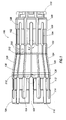
- the tool 100 has a cone 102 preferably made of 4140 steel, although other strong, ductile metallic or composite materials may be used.
- the cone 102 has expansion slots 104 arranged to facilitate radial flexibility.
- the expansion slots 104 are preferably arranged in a symmetrical pattern as shown in Figure 1, but may be shaped differently or arranged asymmetrically.
- the cone 102 preferably has a forward portion 106 substantially cylindrical in shape.
- the forward portion 106 preferably has a raised section 108, preferably near its forwardmost end 110.
- An aft portion 112 of the cone 102 is also typically substantially cylindrical in shape and larger in overall diameter than the raised section 108 of the forward portion 106.
- the aft portion 112 also preferably has a raised section 114, typically near its aftmost end 116.
- a mid portion 120 is disposed between the forward portion 106 and aft portion 112.
- the mid portion 120 typically graduates from a first cylindrical portion 122, of the same outside diameter as the raised section 108 of the forward portion 106, to a frustum-shaped section 124, to a second cylindrical portion 126, of the same outside diameter as the raised section 114 of the aft portion 112.
- the exact configuration of the cone 102 is not crucial to the concept of the invention as long as the cone 102 is shaped in such a way as to forcibly cause a tubular to expand as the cone 102 is forcibly moved through the tubular.
- hardened wear faces 128 are preferably attached to the exterior of cone 102.
- the wear faces 128 cover the outer periphery of the mid portion 120 of the cone, and the raised sections fore 108 and aft 114.
- the wear faces 128 are preferably made from tool steel, D-2 steel, molybdenum disulphide, or tungsten carbide, although other hard, wear-resistant metals or composites may be used.
- the wear faces 128 are preferably laser welded to the underlying surface 130 of the cone 102.
- the wear faces may also be attached to the cone surface by other means such as chemical or mechanical bonding.
- Niches 132 are provided in the outer periphery of the cone 102 for receiving wear face inlays 129.
- Niches 132 and inlays 129 may extend the length of frustum-shaped section 124, as shown, or over any portion of the cone outer surface 130.
- the wear face inlays 129 are preferably laser welded in position, but may be attached by other means, such as chemical or mechanical bonding.
- the wear faces 128 are in the form of rings 134, preferably made up of segments 136 connected by connectors 138.
- the wear faces 128 are preferably floatingly attached to the cone 102 buy may be chemically or mechanically attached to the cone 102.
- the floating attachment 140 is designed to allow the cone 102 to flex independently of the wear faces 128.
- Preferably apertures 142 in the wear faces 128 are provided and align with corresponding expansion slots 104 in the cone 102.
- Fasteners 146 preferably countersunk pins or bolts, retain the wear faces 128 in position relative to the cone while allowing radially slidability.
- This floating attachment arrangement may be used with any of the embodiments described herein.
- Figure 4 shows an alternate embodiment of cone 102 and wear faces 128.
- the mid-portion 120 of the cone 102 comprises multiple frusto-conical sections 150 each of which may employ separate wear faces 128.
- the number, placement and attachment means of the wear faces may vary.
- the flexible expansion tool 100 is introduced into the interior of the expandable tubular 400 in well 12.
- the flexible expansion tool 100 may be reduced in diameter to facilitate its deployment.
- the tool 100 is actuated and the cone 102 is radially expanded so that the wear faces 128 contact the inner surface 402 of the unexpanded tubular 400.
- the expansion is continued, forcibly causing the unexpanded tubular 400 to permanently assume an expanded diameter.
- the tool 100 is forced axially along the tubular, expanding the tubular as it progresses along the tubular length.
- the tool 100 may be oriented to allow movement downhole or uphole, causing the radial expansion of the tubular 400 for any desired length.
- the tool 100 has the advantages of radial flexibility to facilitate contracting or expanding as conditions warrant. Further advantages in reduced friction and tool longevity are realized by the fact that the surfaces of the tool that come in contact with the tubular are lined with wear faces.
- the expansion tool 100 may be variably expandable, that is, having a selectively variable diameter to allow the mandrel to reduce its diameter to successfully manoeuvre through areas of the wellbore having a smaller diameter, as shown in Figure 4, or to enlarge its diameter to more completely expand a tubular, such as screen 400, thereby eliminating or reducing any pockets or gaps 22 between the expanded tubular 400 and the wellbore wall 18.
- the variations in diameter may be automatically controlled, such that the expansion tool 100 regulates its own diameter, based on well conditions as measured by sensors 200.
- Variable expansion is accomplished via dilator 212, preferably mounted to the interior 103 surface of the cone 102.
- Multiple dilators may be employed at various locations on the cone.
- the dilator may be designed to operate within a preselected range of expansion force so that minimum wellbore contact stress is achieved. In operation, the dilator may control the diameter of the cone based on contact stress.
- variable diameter cone 102 has one or more sensors 200, preferably attached to the frustum section 120, for detecting one or more physical parameters germane to radial expansion of the tubular, and converting the physical parameters to one or more electronic signals.
- the sensors may measure contact stress, expansion and compression forces, axial force, downhole pressure, temperature and the like, and any other parameters as desired.
- Sensors 200 may also measure the diameter of the mandrel at any given point along the wellbore, thereby providing a means of mapping the diameter of the expanded tubular.
- a processor circuit is electrically connected to the sensors 200 for processing sensor signals.
- the processor circuit is preferably a commercially available multipurpose microprocessor such as those manufactured by MOTOROLA (registered trade mark) or INTEL (registered trade mark) , may also be a more specialized ASIC.
- the processor circuit may be electrically associated with an electronic memory circuit and/or a transceiver circuit.
- an electronic memory circuit is used to store date signals from the processor circuit and the transceiver circuit is used to send signals as they are generated, to an operator at the surface or to receive signals from the surface relating to control of the tool.
- a control circuit is electrically connected to the processor circuit.
- a dilator 212 preferably electromechanical, is in turn electrically connected to the control circuit. The dilator 212 is in mechanical contact with the cone 102, preferably within the interior 103.
- the dilator 212 is used to exert a force extending radially through the cone 102. By increasing or relaxing this radial force, the diameter of the cone 102 can be expanded or contracted.
- the electronic signals obtained from the sensors 200 and/or signals from the surface can be used to automatically regulate the degree of expansion of the cone 102.
- a digital signal processing circuit, wavelet analysis circuit, or neural network circuit may be used to generate instructions to the control circuit, preferably in real-time response to sensor 200 signals.
- the cone 102 may have a seal 300.
- the seal 300 is a controlled-egress seal, preferably located at the forward end 110 of the cone 102.
- the seal 300 maintains sealing contact with the inner surface 402 of the tubular 400.
- the sealing contact is not fluid tight, but permits a controlled amount of fluid F to pass between the seal 300 and the inner surface 402 of the tubular 400.
- the seal 300 is preferably a labyrinth-type seal, which permits egress of a relatively small amount of well fluid F through the seal.
- the labyrinth-type seal element 302 is advantageous in terms of decreased wear over an elastomeric seal.
- the labyrinth seal 3-2 also provides an advantage in directing fluid flow ahead of the tool 100, reducing the quantity of debris D in the wellbore and in annular space 20, that could otherwise become forced into openings 404 in the screen assembly 400 upon expansion.
- the seal element 302 is preferably made from stainless steel or composite material, but may be from any material suitably resistant to corrosion.
- the seal element 302 is typically attached to a seal carrier 304, which is in turn mechanically attached to the surface of the cone 102 such as by bolting or welding.
- the exact configuration of the labyrinth seal 300 is not critical to the invention.
- the seal may be designed to provide controlled fluid flow without physically contacting the tubular itself.
- the seal location on cone 102 may vary without departing from the spirit of the invention.
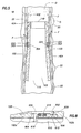
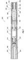
- a screen expansion apparatus 500 is shown disposed in a wellbore 502, typically uncased, for expanding screen assembly 400.
- the screen expansion apparatus 500 is connected to tubing 504 in the conventional manner.
- Tubing 504 can be rolled tubing or jointed pipe string, and while the wellbore is illustrated in only one manner, it may be vertical, deviated or horizontal.
- Screen expander 500 has an upper body 506 and lower body 508.
- the upper body 506 is provided with anchoring mechanism 510 movable between a retracted position 512, as shown in Figure 6, and an extended position 514, as shown in Figure 7.
- Anchoring mechanism may be of any type known in the art, such as slips, as shown, or a packer, and preferably operates from fluid pressure supplied through the tubing string 504.
- the anchoring mechanism may include multiple devices located at various locations along the length of the tool 500. In the retracted position 512, the slips do not interfere with movement of the screen expander apparatus 500 within the wellbore 502 or within the screen assembly 400.
- the slips engage the screen assembly wall or wellbore, thereby locking the upper body 506 of the screen expander 500 in place. Bleeding pressure from the tubing 504 will release the anchoring mechanism 510, as the anchoring mechanism 510 will return to the retracted position 512.
- the upper body 506 further comprises a force generator 516.
- the force generator 516 may be of any kind known in the art and preferably is a hydraulic ram operated using fluid pressure supplied through tubing string 504.
- the force generator 516 preferably includes a force multiplier 518 such as the double-piston assembly, as shown.
- the force multiplier 518 has a primary 520 and a secondary 522 piston, operable as is known in the art.
- the force generator 516, or hydraulic ram is operable to extend the lower body 508 of the expansion apparatus 500 relative to the upper body 506.
- the lower body 508 supports expansion cone assembly 524 including mandrel 526 having a ramp 528 upon which cone 530 slides.
- the expansion cone assembly can be of any type known in the art, including the cones heretofore discussed.
- the expansion cone assembly 524 shown in Figures 6 and 7 operates on fluid pressure as supplied through the tubing 504. Pressure, supplied through port 532, drives cone piston 534 and internal slip 536 to move slidable cone 530 up ramp 528 of mandrel 526. When the cone is moved from its retracted position to its expanded position the cone can be used to expand the screen assembly 400 as the lower body 508 of the screen expansion apparatus 500 is extended.
- the screen expansion device 500 is lowered into the wellbore 502 to a desired depth adjacent an unexpanded screen assembly 400.
- the anchoring mechanism 510 and expansion cone 530 are in their retracted positions 512 and 538, respectively.
- the expansion cone 530 is moved to the expanded position 540 wherein the cone 530 contacts the screen assembly 400 thereby expanding the screen.
- the cone 530 is moved to its expanded state 540 by providing fluid pressure, via the tubing string 504, through ports 532 to drive cone piston 534 which in turn powers the cone 530 up ramp 528 of mandrel 526.
- Internal slip 536 is operable to maintain the cone's position and allow later retraction. Expansion of the cone 530 may involve setting the anchoring mechanism 510 and stroking the force generator 516, thereby extending lower body 508.
- the screen assembly 400 may be radially expanded by the longitudinal advancement of the cone through the screen.
- the anchoring mechanism 510 such as the slips shown, are moved from the retracted position 512 to the extended position 514 to anchor the upper body 506 of the expansion apparatus 500 in the wellbore 502 or screen assembly 400.
- the force generator 516 is activated, extending the lower body 508 of the expansion apparatus 500 with respect to the upper body 506 and forcing the expansion cone 530 longitudinally through the screen 400, thereby expanding the screen.
- the anchoring mechanism 510 is retracted, by lowering the fluid pressure in the tubing.
- the cone 510 in contact with the screen assembly 400, now acts to anchor the lower body 508 of the expansion apparatus 500 with respect to the wellbore 502.
- the force generator is then retracted.
- the upper body 506 is pulled downhole towards the cone 530.
- cone 102 can include joint assemblies 600 for added flexibility in the expandable cone.
- the increase in flexibility reduces the stress placed on the expandable tubular by the expansion cone.
- the knuckle joint assembly configuration can be repeated multiple times throughout the length of the expansion tool 100 and can be sued in conjunction with other tool features herein, such as a hardened wear face 128.
- Joint assembly 600 is preferably a "knuckle joint" assembly, but can be other jointed or articulated assemblies as are known in the art.
- Knuckle joint 600 forms an articulating joint allowing one cone section 102a to move relative to another cone section 102b about a pivot point 602.
- Joint arm 604, having a pivot ball 606 of arm 604 attaches to cone section 102a, while the ball 606 of arm 604 mates with socket 608 which may be integral with cone section 102b as shown.
- Retaining arm 610 is attached to cone section 102b. Joint arm 604 is captured by recess 612 in the retaining arm 610.
- a flexible sealing element such as packing 614, with vee-stop 616, seal the joint assembly 600 while allowing limited movement of joint arm 604 about the pivot joint.
- Use of multiple joint assemblies spaced along the length of cone 102 would allow for greater flexibility and can be added as desired.
Landscapes
- Life Sciences & Earth Sciences (AREA)
- Engineering & Computer Science (AREA)
- Geology (AREA)
- Mining & Mineral Resources (AREA)
- Physics & Mathematics (AREA)
- Environmental & Geological Engineering (AREA)
- Fluid Mechanics (AREA)
- General Life Sciences & Earth Sciences (AREA)
- Geochemistry & Mineralogy (AREA)
- Earth Drilling (AREA)
Abstract
Description
In an embodiment, the cone body has at least on pivotal joint assembly.
In an embodiment, the expansion cone has an interior surface, the at least one dilator connected to the interior surface. The or each dilator may be operable within a preselected range of expansion force.
Preferably, the controlled egress seal is a labyrinthine seal. More preferably, the labyrinthine seal is of stainless steel.
In an embodiment, the force generator comprises a double-piston assembly. The anchoring mechanism and force generator may be operable via fluid pressure.
In an embodiment, the expansion cone apparatus further comprises at least one wear face attached to the cone body. The at least one wear face may comprise at least one wear ring. The expansion cone body may have expansion slots therein.
The expansion cone may further comprise at least one wear face attached to the cone body.2 The or each wear face may comprises at least one wear ring. The expansion cone body may have expansion slots therein.
Claims (10)
- An expansion cone apparatus for use in expanding a tubular in a subterranean well comprising: a cone body; and at least one wear face attached to the cone body.
- An expansion cone apparatus according to Claim 1, wherein the cone body is 4140 steel.
- A method of downhole tubular expansion comprising of the steps of: positioning an expansion cone in a tubular positioned in a subterranean wellbore, the expansion cone having a cone body and at least one wear face attached to the cone body; expanding the expansion cone; and moving the expanded cone axially along the tubular thereby radially expanding the tubular.
- An expansion tool for use in expanding a tubular in a subterranean wellbore comprising: an automatically variable diameter expansion cone; and at least one sensor for detecting parameters within the wellbore, the at least one sensor operably connected to the variable diameter expansion cone, the diameter of the expansion cone automatically varying based on the detected parameters.
- A method of downhole tubular expansion, the tubular disposed in a wellbore of a subterranean well, comprising of the steps of: positioning an automatically variable diameter expansion cone in the tubular; expanding the cone to a selected diameter; advancing the cone along the tubular, thereby radially expanding the tubular; and automatically varying the diameter of the cone as the cone is advanced along the tubular.
- An expansion cone apparatus for use in expanding a tubular in a subterranean well comprising: a cone body having an exterior surface; and a controlled egress seal on the exterior surface of the cone body for sealing contact with the tubular.
- A method of tubular expansion, the tubular positioned in the wellbore of a subterranean well, comprising the steps of: positioning an expansion cone in the tubular, the expansion cone having a cone body with an exterior surface and a controlled egress seal on the exterior surface for sealing contact with the tubular; expanding the expansion cone; and moving the expanded cone axially along the tubular thereby expanding the tubular.
- A method of expanding a screen assembly in a subterranean wellbore, the method comprising the steps of: (1) positioning, adjacent the screen assembly, an expansion tool having an upper and lower body, an anchoring mechanism located in the upper body, an expansion cone assembly located in the lower body, and a force generator operable to vary the distance between the anchoring mechanism and the expansion assembly; (2) radially expanding the expansion assembly; (3) setting the anchoring mechanism; (4) activating the force generator to lengthen the distance between the anchoring mechanism and the expansion assembly, thereby forcing the expansion assembly through the screen assembly and radially expanding the screen assembly; (5) retracting the anchoring mechanism; (6) activating the force generator to shorten the distance between the anchoring mechanism and the expansion assembly; and (7) repeating steps (3) to (6) as desired.
- An expansion cone apparatus for use in expanding tubulars in a subterranean well comprising: an expansion cone body having multiple cone sections; and at least one joint assembly pivotally connecting the cone sections.
- A method of tubular expansion, the tubular positioned in the wellbore of a subterranean well, comprising the steps of: positioning an expansion cone in the tubular, the expansion cone having an expansion cone body with multiple cone body sections and at least one joint assembly pivotally connecting the cone sections; expanding the expansion cone; and moving the expanded cone axially along the tubular thereby radially expanding the tubular.
Applications Claiming Priority (2)
| Application Number | Priority Date | Filing Date | Title |
|---|---|---|---|
| US10/047,628 US6722427B2 (en) | 2001-10-23 | 2001-10-23 | Wear-resistant, variable diameter expansion tool and expansion methods |
| US47628 | 2001-10-23 |
Publications (3)
| Publication Number | Publication Date |
|---|---|
| EP1306519A2 true EP1306519A2 (en) | 2003-05-02 |
| EP1306519A3 EP1306519A3 (en) | 2005-07-06 |
| EP1306519B1 EP1306519B1 (en) | 2007-03-07 |
Family
ID=21950024
Family Applications (1)
| Application Number | Title | Priority Date | Filing Date |
|---|---|---|---|
| EP02257321A Expired - Lifetime EP1306519B1 (en) | 2001-10-23 | 2002-10-22 | Wear-resistant, variable diameter expansion tool and expansion methods |
Country Status (3)
| Country | Link |
|---|---|
| US (2) | US6722427B2 (en) |
| EP (1) | EP1306519B1 (en) |
| DE (1) | DE60218597D1 (en) |
Cited By (24)
| Publication number | Priority date | Publication date | Assignee | Title |
|---|---|---|---|---|
| WO2005088070A1 (en) * | 2004-03-08 | 2005-09-22 | Shell Internationale Research Maatschappij B.V. | Dual cone expander for expanding a tubular element to different diameters |
| WO2005088068A1 (en) * | 2004-03-08 | 2005-09-22 | Shell Oil Company | Expander cone with unaligned deformable segments |
| GB2393986B (en) * | 2002-10-08 | 2005-12-07 | Weatherford Lamb | Improved expander tool for downhole use |
| GB2398811B (en) * | 2003-02-26 | 2006-07-12 | Weatherford Lamb | Tubing expansion |
| US7117940B2 (en) | 2004-03-08 | 2006-10-10 | Shell Oil Company | Expander for expanding a tubular element |
| US7131498B2 (en) | 2004-03-08 | 2006-11-07 | Shell Oil Company | Expander for expanding a tubular element |
| GB2435280A (en) * | 2006-02-17 | 2007-08-22 | Enventure Global Technology | An expandable cone or tubular having a coating of tungsten disulfide |
| US7380593B2 (en) | 2001-11-28 | 2008-06-03 | Shell Oil Company | Expandable tubes with overlapping end portions |
| US7398832B2 (en) | 2002-06-10 | 2008-07-15 | Enventure Global Technology, Llc | Mono-diameter wellbore casing |
| US7410000B2 (en) | 2001-01-17 | 2008-08-12 | Enventure Global Technology, Llc. | Mono-diameter wellbore casing |
| US7438132B2 (en) | 1999-03-11 | 2008-10-21 | Shell Oil Company | Concentric pipes expanded at the pipe ends and method of forming |
| US7438133B2 (en) | 2003-02-26 | 2008-10-21 | Enventure Global Technology, Llc | Apparatus and method for radially expanding and plastically deforming a tubular member |
| US7503393B2 (en) | 2003-01-27 | 2009-03-17 | Enventure Global Technology, Inc. | Lubrication system for radially expanding tubular members |
| US7513313B2 (en) | 2002-09-20 | 2009-04-07 | Enventure Global Technology, Llc | Bottom plug for forming a mono diameter wellbore casing |
| US7552776B2 (en) | 1998-12-07 | 2009-06-30 | Enventure Global Technology, Llc | Anchor hangers |
| US7559365B2 (en) | 2001-11-12 | 2009-07-14 | Enventure Global Technology, Llc | Collapsible expansion cone |
| US7597140B2 (en) | 2003-05-05 | 2009-10-06 | Shell Oil Company | Expansion device for expanding a pipe |
| US7712522B2 (en) | 2003-09-05 | 2010-05-11 | Enventure Global Technology, Llc | Expansion cone and system |
| US7793721B2 (en) | 2003-03-11 | 2010-09-14 | Eventure Global Technology, Llc | Apparatus for radially expanding and plastically deforming a tubular member |
| US7819185B2 (en) | 2004-08-13 | 2010-10-26 | Enventure Global Technology, Llc | Expandable tubular |
| US7886831B2 (en) | 2003-01-22 | 2011-02-15 | Enventure Global Technology, L.L.C. | Apparatus for radially expanding and plastically deforming a tubular member |
| WO2011008908A3 (en) * | 2009-07-15 | 2011-04-28 | Enventure Global Technology, Llc | Expansion system for expandable tubulars |
| WO2013148110A3 (en) * | 2012-03-30 | 2014-06-26 | Halliburton Energy Services, Inc. | Expansion tool for non-cemented casing-casing annulus (cca) wellbores |
| WO2013148115A3 (en) * | 2012-03-30 | 2014-08-28 | Halliburton Energy Services, Inc. | Expansion tool for non-cemented casing-casing annulus (cca) wellbores |
Families Citing this family (108)
| Publication number | Priority date | Publication date | Assignee | Title |
|---|---|---|---|---|
| AU2001269810B2 (en) | 1998-11-16 | 2005-04-07 | Shell Oil Company | Radial expansion of tubular members |
| US7121352B2 (en) | 1998-11-16 | 2006-10-17 | Enventure Global Technology | Isolation of subterranean zones |
| US7603758B2 (en) | 1998-12-07 | 2009-10-20 | Shell Oil Company | Method of coupling a tubular member |
| US6823937B1 (en) | 1998-12-07 | 2004-11-30 | Shell Oil Company | Wellhead |
| US6557640B1 (en) | 1998-12-07 | 2003-05-06 | Shell Oil Company | Lubrication and self-cleaning system for expansion mandrel |
| WO2003004819A2 (en) | 2001-07-06 | 2003-01-16 | Enventure Global Technology | Liner hanger |
| US7231985B2 (en) | 1998-11-16 | 2007-06-19 | Shell Oil Company | Radial expansion of tubular members |
| US7357188B1 (en) | 1998-12-07 | 2008-04-15 | Shell Oil Company | Mono-diameter wellbore casing |
| GB2356651B (en) | 1998-12-07 | 2004-02-25 | Shell Int Research | Lubrication and self-cleaning system for expansion mandrel |
| US7195064B2 (en) | 1998-12-07 | 2007-03-27 | Enventure Global Technology | Mono-diameter wellbore casing |
| US6725919B2 (en) | 1998-12-07 | 2004-04-27 | Shell Oil Company | Forming a wellbore casing while simultaneously drilling a wellbore |
| US7363984B2 (en) | 1998-12-07 | 2008-04-29 | Enventure Global Technology, Llc | System for radially expanding a tubular member |
| GB2344606B (en) * | 1998-12-07 | 2003-08-13 | Shell Int Research | Forming a wellbore casing by expansion of a tubular member |
| US7185710B2 (en) | 1998-12-07 | 2007-03-06 | Enventure Global Technology | Mono-diameter wellbore casing |
| AU770359B2 (en) | 1999-02-26 | 2004-02-19 | Shell Internationale Research Maatschappij B.V. | Liner hanger |
| JP3461750B2 (en) * | 1999-03-04 | 2003-10-27 | パナソニック コミュニケーションズ株式会社 | Communication apparatus, communication method, and caller information registration method |
| CA2306656C (en) | 1999-04-26 | 2006-06-06 | Shell Internationale Research Maatschappij B.V. | Expandable connector for borehole tubes |
| US7350563B2 (en) | 1999-07-09 | 2008-04-01 | Enventure Global Technology, L.L.C. | System for lining a wellbore casing |
| US7048067B1 (en) | 1999-11-01 | 2006-05-23 | Shell Oil Company | Wellbore casing repair |
| US7234531B2 (en) | 1999-12-03 | 2007-06-26 | Enventure Global Technology, Llc | Mono-diameter wellbore casing |
| US7100684B2 (en) | 2000-07-28 | 2006-09-05 | Enventure Global Technology | Liner hanger with standoffs |
| US6799637B2 (en) | 2000-10-20 | 2004-10-05 | Schlumberger Technology Corporation | Expandable tubing and method |
| US6789621B2 (en) * | 2000-08-03 | 2004-09-14 | Schlumberger Technology Corporation | Intelligent well system and method |
| AU9269501A (en) | 2000-09-18 | 2002-03-26 | Shell Oil Co | Liner hanger with sliding sleeve valve |
| WO2002053867A2 (en) | 2001-01-03 | 2002-07-11 | Enventure Global Technology | Mono-diameter wellbore casing |
| AU9480201A (en) | 2000-10-02 | 2002-04-15 | Shell Oil Co | Method and apparatus for casing expansion |
| US7100685B2 (en) | 2000-10-02 | 2006-09-05 | Enventure Global Technology | Mono-diameter wellbore casing |
| NO335594B1 (en) | 2001-01-16 | 2015-01-12 | Halliburton Energy Serv Inc | Expandable devices and methods thereof |
| GB0109711D0 (en) * | 2001-04-20 | 2001-06-13 | E Tech Ltd | Apparatus |
| GB2395506B (en) | 2001-07-06 | 2006-01-18 | Eventure Global Technology | Liner hanger |
| US7258168B2 (en) | 2001-07-27 | 2007-08-21 | Enventure Global Technology L.L.C. | Liner hanger with slip joint sealing members and method of use |
| US7243731B2 (en) * | 2001-08-20 | 2007-07-17 | Enventure Global Technology | Apparatus for radially expanding tubular members including a segmented expansion cone |
| WO2003078785A2 (en) * | 2002-03-13 | 2003-09-25 | Eventure Global Technology | Collapsible expansion cone |
| AU2002319813A1 (en) | 2001-09-07 | 2003-03-24 | Enventure Global Technology | Adjustable expansion cone assembly |
| US6722427B2 (en) * | 2001-10-23 | 2004-04-20 | Halliburton Energy Services, Inc. | Wear-resistant, variable diameter expansion tool and expansion methods |
| GB0128667D0 (en) | 2001-11-30 | 2002-01-23 | Weatherford Lamb | Tubing expansion |
| US7661470B2 (en) * | 2001-12-20 | 2010-02-16 | Baker Hughes Incorporated | Expandable packer with anchoring feature |
| WO2003058022A2 (en) | 2001-12-27 | 2003-07-17 | Enventure Global Technology | Seal receptacle using expandable liner hanger |
| EP1485567B1 (en) | 2002-02-15 | 2008-12-17 | Enventure Global Technology | Mono-diameter wellbore casing |
| EP1985798A2 (en) | 2002-04-12 | 2008-10-29 | Enventure Global Technology | Protective sleeve for threated connections for expandable liner hanger |
| CA2482278A1 (en) | 2002-04-15 | 2003-10-30 | Enventure Global Technology | Protective sleeve for threaded connections for expandable liner hanger |
| GB2426993B (en) | 2002-05-29 | 2007-05-02 | Enventure Global Technology | System for radially expanding a tubular member |
| EP1540128A4 (en) | 2002-08-23 | 2006-07-19 | Enventure Global Technology | Interposed joint sealing layer method of forming a wellbore casing |
| AU2003258274A1 (en) | 2002-08-23 | 2004-03-11 | Enventure Global Technology | Magnetic impulse applied sleeve method of forming a wellbore casing |
| WO2004027392A1 (en) | 2002-09-20 | 2004-04-01 | Enventure Global Technology | Pipe formability evaluation for expandable tubulars |
| GB2410280B (en) | 2002-09-20 | 2007-04-04 | Enventure Global Technology | Self-lubricating expansion mandrel for expandable tubular |
| AU2003263859A1 (en) | 2002-09-20 | 2004-04-08 | Enventure Global Technology | Protective sleeve for expandable tubulars |
| US6843319B2 (en) * | 2002-12-12 | 2005-01-18 | Weatherford/Lamb, Inc. | Expansion assembly for a tubular expander tool, and method of tubular expansion |
| GB0303422D0 (en) * | 2003-02-13 | 2003-03-19 | Read Well Services Ltd | Apparatus and method |
| WO2004083591A2 (en) * | 2003-03-17 | 2004-09-30 | Enventure Global Technology | Apparatus and method for radially expanding a wellbore casing using an adaptive expansion system |
| CA2523862C (en) | 2003-04-17 | 2009-06-23 | Enventure Global Technology | Apparatus for radially expanding and plastically deforming a tubular member |
| ATE354718T1 (en) * | 2003-04-25 | 2007-03-15 | Shell Int Research | EXPANDING SYSTEM FOR THE INSTEADIAL EXPANSION OF A TUBULAR ELEMENT |
| DE602004005696T2 (en) * | 2003-04-25 | 2007-12-27 | Shell Internationale Research Maatschappij B.V. | ADDITIONAL SYSTEM FOR STEP-BY-STEP Widening of a TUBE-ELEMENT |
| US7441606B2 (en) * | 2003-05-01 | 2008-10-28 | Weatherford/Lamb, Inc. | Expandable fluted liner hanger and packer system |
| US7093656B2 (en) * | 2003-05-01 | 2006-08-22 | Weatherford/Lamb, Inc. | Solid expandable hanger with compliant slip system |
| US7028780B2 (en) * | 2003-05-01 | 2006-04-18 | Weatherford/Lamb, Inc. | Expandable hanger with compliant slip system |
| US20050166387A1 (en) | 2003-06-13 | 2005-08-04 | Cook Robert L. | Method and apparatus for forming a mono-diameter wellbore casing |
| EP1658416B1 (en) * | 2003-08-25 | 2006-12-27 | Jeffery A. Spray | Expandable tubulars for use in geologic structures, methods for expanding tubulars, and methods of manufacturing expandable tubulars |
| GB2411918B (en) * | 2004-03-12 | 2006-11-22 | Schlumberger Holdings | System and method to seal using a swellable material |
| US20050269074A1 (en) * | 2004-06-02 | 2005-12-08 | Chitwood Gregory B | Case hardened stainless steel oilfield tool |
| US7117941B1 (en) * | 2005-04-11 | 2006-10-10 | Halliburton Energy Services, Inc. | Variable diameter expansion tool and expansion methods |
| US7434616B2 (en) * | 2005-05-27 | 2008-10-14 | Halliburton Energy Services, Inc. | System and method for fluid control in expandable tubing |
| GB0520860D0 (en) * | 2005-10-14 | 2005-11-23 | Weatherford Lamb | Tubing expansion |
| US7607476B2 (en) * | 2006-07-07 | 2009-10-27 | Baker Hughes Incorporated | Expandable slip ring |
| CA2616055C (en) * | 2007-01-03 | 2012-02-21 | Weatherford/Lamb, Inc. | System and methods for tubular expansion |
| US20090308588A1 (en) * | 2008-06-16 | 2009-12-17 | Halliburton Energy Services, Inc. | Method and Apparatus for Exposing a Servicing Apparatus to Multiple Formation Zones |
| US20100032167A1 (en) * | 2008-08-08 | 2010-02-11 | Adam Mark K | Method for Making Wellbore that Maintains a Minimum Drift |
| US20100044029A1 (en) * | 2008-08-20 | 2010-02-25 | Baker Hughes Incorporated | Active control and/or monitoring of expandable tubular devices |
| US8251137B2 (en) * | 2008-08-20 | 2012-08-28 | Enventure Global Technology, Llc | Geometrically optimized expansion cone |
| US7921921B2 (en) * | 2008-09-24 | 2011-04-12 | Baker Hughes Incorporated | Downhole backup system and method |
| US8443881B2 (en) | 2008-10-13 | 2013-05-21 | Weatherford/Lamb, Inc. | Expandable liner hanger and method of use |
| US7980302B2 (en) * | 2008-10-13 | 2011-07-19 | Weatherford/Lamb, Inc. | Compliant expansion swage |
| AU2012211360B2 (en) * | 2008-10-13 | 2015-01-22 | Weatherford Technology Holdings, Llc | Compliant expansion swage |
| US8684096B2 (en) * | 2009-04-02 | 2014-04-01 | Key Energy Services, Llc | Anchor assembly and method of installing anchors |
| US9303477B2 (en) | 2009-04-02 | 2016-04-05 | Michael J. Harris | Methods and apparatus for cementing wells |
| US8276675B2 (en) * | 2009-08-11 | 2012-10-02 | Halliburton Energy Services Inc. | System and method for servicing a wellbore |
| US8668012B2 (en) | 2011-02-10 | 2014-03-11 | Halliburton Energy Services, Inc. | System and method for servicing a wellbore |
| US8668016B2 (en) | 2009-08-11 | 2014-03-11 | Halliburton Energy Services, Inc. | System and method for servicing a wellbore |
| US8695710B2 (en) | 2011-02-10 | 2014-04-15 | Halliburton Energy Services, Inc. | Method for individually servicing a plurality of zones of a subterranean formation |
| US8272443B2 (en) * | 2009-11-12 | 2012-09-25 | Halliburton Energy Services Inc. | Downhole progressive pressurization actuated tool and method of using the same |
| US8261842B2 (en) | 2009-12-08 | 2012-09-11 | Halliburton Energy Services, Inc. | Expandable wellbore liner system |
| US8408317B2 (en) * | 2010-01-11 | 2013-04-02 | Tiw Corporation | Tubular expansion tool and method |
| US8893811B2 (en) | 2011-06-08 | 2014-11-25 | Halliburton Energy Services, Inc. | Responsively activated wellbore stimulation assemblies and methods of using the same |
| US8899334B2 (en) | 2011-08-23 | 2014-12-02 | Halliburton Energy Services, Inc. | System and method for servicing a wellbore |
| US8662178B2 (en) | 2011-09-29 | 2014-03-04 | Halliburton Energy Services, Inc. | Responsively activated wellbore stimulation assemblies and methods of using the same |
| CN103089183A (en) * | 2011-10-31 | 2013-05-08 | 中国石油化工股份有限公司 | Double bellmouth type expansion sleeve packing tool and operating method thereof |
| US8991509B2 (en) | 2012-04-30 | 2015-03-31 | Halliburton Energy Services, Inc. | Delayed activation activatable stimulation assembly |
| US9784070B2 (en) | 2012-06-29 | 2017-10-10 | Halliburton Energy Services, Inc. | System and method for servicing a wellbore |
| US9157288B2 (en) | 2012-07-19 | 2015-10-13 | General Plastics & Composites, L.P. | Downhole tool system and method related thereto |
| CN102937009B (en) * | 2012-10-10 | 2014-12-10 | 西安三环科技开发总公司 | Top pressure bearing expansion pipe construction operation method |
| CN103775015B (en) * | 2012-10-18 | 2016-11-16 | 中国石油化工股份有限公司 | Expand instrument under cased well and use its expansion sleeve method |
| WO2014109748A1 (en) | 2013-01-10 | 2014-07-17 | Halliburton Energy Services, Inc. | Boost assisted force balancing setting tool |
| CN104005725B (en) * | 2013-02-26 | 2016-12-28 | 天津大港油田钻采技术开发公司 | Expansion tube twin-stage expansion gear |
| US20140305627A1 (en) * | 2013-04-15 | 2014-10-16 | Halliburton Energy Services, Inc. | Anti-wear device for composite packers and plugs |
| CN103433395A (en) * | 2013-09-03 | 2013-12-11 | 西安胜智航空科技有限公司 | Expanding device for shape memory alloy pipe joint |
| EP3145720B8 (en) | 2014-05-20 | 2023-04-12 | Velox-Puredigital Ltd. | Printing system and method |
| US20180187527A1 (en) * | 2015-07-01 | 2018-07-05 | Shell Oil Company | Method and system for switching a functionality of a liner expansion tool |
| US10914142B2 (en) | 2016-12-30 | 2021-02-09 | Halliburton Energy Services, Inc. | Expansion assembly for expandable liner hanger |
| US10941644B2 (en) | 2018-02-20 | 2021-03-09 | Saudi Arabian Oil Company | Downhole well integrity reconstruction in the hydrocarbon industry |
| US11187068B2 (en) * | 2019-01-31 | 2021-11-30 | Saudi Arabian Oil Company | Downhole tools for controlled fracture initiation and stimulation |
| US11898422B2 (en) * | 2020-11-03 | 2024-02-13 | Saudi Arabian Oil Company | Diamond coating on the cone for expandable tubulars |
| US11619097B2 (en) | 2021-05-24 | 2023-04-04 | Saudi Arabian Oil Company | System and method for laser downhole extended sensing |
| US11725504B2 (en) | 2021-05-24 | 2023-08-15 | Saudi Arabian Oil Company | Contactless real-time 3D mapping of surface equipment |
| US11954800B2 (en) | 2021-12-14 | 2024-04-09 | Saudi Arabian Oil Company | Converting borehole images into three dimensional structures for numerical modeling and simulation applications |
| US11739616B1 (en) | 2022-06-02 | 2023-08-29 | Saudi Arabian Oil Company | Forming perforation tunnels in a subterranean formation |
| US12203333B2 (en) * | 2022-06-06 | 2025-01-21 | Halliburton Energy Services, Inc. | Composite wellbore sealing device |
| CN117927197A (en) * | 2024-03-11 | 2024-04-26 | 中海油田服务股份有限公司 | Variable-diameter combined expansion cone for expansion screen pipe |
| US20260002420A1 (en) * | 2024-03-29 | 2026-01-01 | PetroTool International LLC | Tubing Anchor and Catcher Tool with Fluid-Enhanced Cone for Increased Fluid Flow |
Family Cites Families (95)
| Publication number | Priority date | Publication date | Assignee | Title |
|---|---|---|---|---|
| US1336738A (en) | 1920-04-13 | Well-packer | ||
| US2011036A (en) * | 1934-02-20 | 1935-08-13 | Andrew J Colmerauer | Casing roller |
| US2214226A (en) | 1939-03-29 | 1940-09-10 | English Aaron | Method and apparatus useful in drilling and producing wells |
| US2812025A (en) | 1955-01-24 | 1957-11-05 | James U Teague | Expansible liner |
| US3203451A (en) | 1962-08-09 | 1965-08-31 | Pan American Petroleum Corp | Corrugated tube for lining wells |
| US3195646A (en) | 1963-06-03 | 1965-07-20 | Brown Oil Tools | Multiple cone liner hanger |
| US3477506A (en) | 1968-07-22 | 1969-11-11 | Lynes Inc | Apparatus relating to fabrication and installation of expanded members |
| US3785193A (en) | 1971-04-10 | 1974-01-15 | Kinley J | Liner expanding apparatus |
| US3818734A (en) * | 1973-05-23 | 1974-06-25 | J Bateman | Casing expanding mandrel |
| US3940227A (en) | 1974-06-20 | 1976-02-24 | Strasser Georg J | Expansible mandrel |
| US3934836A (en) | 1974-07-31 | 1976-01-27 | Stamco Division, The Monarch Machine Tool Company | Mandrel assembly |
| US4201364A (en) | 1978-07-27 | 1980-05-06 | Otis Engineering Corporation | Radially expandable tubular valve seal |
| US4210991A (en) | 1978-09-05 | 1980-07-08 | Westinghouse Electric Corp. | Hydraulic expansion swaging of tubes in tubesheet |
| US4212186A (en) | 1978-10-25 | 1980-07-15 | Blattler Joseph F | Pipe expander |
| US4285407A (en) * | 1979-12-17 | 1981-08-25 | Samford Travis L | Straight hole driller |
| US4415029A (en) | 1981-07-23 | 1983-11-15 | Gearhart Industries, Inc. | Downhole well tool and anchoring assembly |
| US4451047A (en) * | 1981-07-31 | 1984-05-29 | Smith International, Inc. | Seal |
| US4629991A (en) | 1984-04-11 | 1986-12-16 | Pa Incorporated | Methods and apparatus for detecting tubular defects having a plurality of expandable arcuate segments |
| US4754543A (en) | 1986-06-30 | 1988-07-05 | Dayco Products, Inc. | Method of making expandable and collapsible mandrel |
| EP0397874B1 (en) | 1988-11-22 | 1997-02-05 | Tatarsky Gosudarstvenny Nauchno-Issledovatelsky I Proektny Institut Neftyanoi Promyshlennosti | Device for closing off a complication zone in a well |
| US5352526A (en) * | 1990-02-06 | 1994-10-04 | Pullman Company | Hardfaced article and process to prevent crack propagation in hardfaced substrates |
| US5070940A (en) | 1990-08-06 | 1991-12-10 | Camco, Incorporated | Apparatus for deploying and energizing submergible electric motor downhole |
| US5070941A (en) | 1990-08-30 | 1991-12-10 | Otis Engineering Corporation | Downhole force generator |
| FR2671735B1 (en) | 1991-01-18 | 1994-04-08 | Pechiney Recherche | PROCESS FOR THE MANUFACTURE OF POROUS TUBES, OF HIGH PERMEABILITY, IN CARBON-CARBON COMPOSITE MATERIAL AND THEIR APPLICATIONS. |
| US5112158A (en) * | 1991-03-25 | 1992-05-12 | Mcconnell W Harry | Underground pipe replacement method and apparatus |
| US5309621A (en) * | 1992-03-26 | 1994-05-10 | Baker Hughes Incorporated | Method of manufacturing a wellbore tubular member by shrink fitting telescoping members |
| MY108830A (en) | 1992-06-09 | 1996-11-30 | Shell Int Research | Method of completing an uncased section of a borehole |
| US5325923A (en) | 1992-09-29 | 1994-07-05 | Halliburton Company | Well completions with expandable casing portions |
| US5396957A (en) | 1992-09-29 | 1995-03-14 | Halliburton Company | Well completions with expandable casing portions |
| US5327765A (en) | 1993-04-05 | 1994-07-12 | Aluminum Company Of America | Internal articulated mandrel for the stretch forming of elongated hollow metal sections |
| FR2710282B1 (en) | 1993-09-25 | 1997-01-24 | Behr Gmbh & Co | Method and device for widening metal tubes of oval section by stretching. |
| US5479699A (en) | 1994-02-07 | 1996-01-02 | Westinghouse Electric Corporation | Apparatus for expanding tubular members |
| US5392626A (en) | 1994-03-16 | 1995-02-28 | The Babcock & Wilcox Company | Flexible hydraulic expansion mandrel |
| US5613557A (en) | 1994-07-29 | 1997-03-25 | Atlantic Richfield Company | Apparatus and method for sealing perforated well casing |
| US6857486B2 (en) * | 2001-08-19 | 2005-02-22 | Smart Drilling And Completion, Inc. | High power umbilicals for subterranean electric drilling machines and remotely operated vehicles |
| MY121223A (en) | 1995-01-16 | 2006-01-28 | Shell Int Research | Method of creating a casing in a borehole |
| UA67719C2 (en) | 1995-11-08 | 2004-07-15 | Shell Int Research | Deformable well filter and method for its installation |
| GB9522942D0 (en) * | 1995-11-09 | 1996-01-10 | Petroline Wireline Services | Downhole tool |
| GB9524109D0 (en) | 1995-11-24 | 1996-01-24 | Petroline Wireline Services | Downhole apparatus |
| DE19603265A1 (en) | 1996-01-30 | 1997-07-31 | Hilti Ag | Expansion dowels |
| US6142230A (en) * | 1996-11-14 | 2000-11-07 | Weatherford/Lamb, Inc. | Wellbore tubular patch system |
| US5785120A (en) | 1996-11-14 | 1998-07-28 | Weatherford/Lamb, Inc. | Tubular patch |
| US5823031A (en) | 1996-11-20 | 1998-10-20 | Tools For Bending, Inc. | Method and apparatus for bulge forming and bending tubes |
| GB9714651D0 (en) | 1997-07-12 | 1997-09-17 | Petroline Wellsystems Ltd | Downhole tubing |
| US6021850A (en) | 1997-10-03 | 2000-02-08 | Baker Hughes Incorporated | Downhole pipe expansion apparatus and method |
| US6029748A (en) | 1997-10-03 | 2000-02-29 | Baker Hughes Incorporated | Method and apparatus for top to bottom expansion of tubulars |
| US6135208A (en) | 1998-05-28 | 2000-10-24 | Halliburton Energy Services, Inc. | Expandable wellbore junction |
| US6189631B1 (en) * | 1998-11-12 | 2001-02-20 | Adel Sheshtawy | Drilling tool with extendable elements |
| GB2343691B (en) | 1998-11-16 | 2003-05-07 | Shell Int Research | Isolation of subterranean zones |
| US7357188B1 (en) | 1998-12-07 | 2008-04-15 | Shell Oil Company | Mono-diameter wellbore casing |
| US6634431B2 (en) | 1998-11-16 | 2003-10-21 | Robert Lance Cook | Isolation of subterranean zones |
| US6712154B2 (en) | 1998-11-16 | 2004-03-30 | Enventure Global Technology | Isolation of subterranean zones |
| US6745845B2 (en) | 1998-11-16 | 2004-06-08 | Shell Oil Company | Isolation of subterranean zones |
| US6263966B1 (en) | 1998-11-16 | 2001-07-24 | Halliburton Energy Services, Inc. | Expandable well screen |
| US6725919B2 (en) | 1998-12-07 | 2004-04-27 | Shell Oil Company | Forming a wellbore casing while simultaneously drilling a wellbore |
| GB2344606B (en) | 1998-12-07 | 2003-08-13 | Shell Int Research | Forming a wellbore casing by expansion of a tubular member |
| AU770008B2 (en) * | 1999-02-25 | 2004-02-12 | Shell Internationale Research Maatschappij B.V. | Mono-diameter wellbore casing |
| AU770359B2 (en) | 1999-02-26 | 2004-02-19 | Shell Internationale Research Maatschappij B.V. | Liner hanger |
| US6598677B1 (en) | 1999-05-20 | 2003-07-29 | Baker Hughes Incorporated | Hanging liners by pipe expansion |
| CA2383150C (en) | 1999-09-06 | 2008-07-29 | E2 Tech Limited | Expandable downhole tubing |
| US7048067B1 (en) * | 1999-11-01 | 2006-05-23 | Shell Oil Company | Wellbore casing repair |
| JP2001137978A (en) * | 1999-11-08 | 2001-05-22 | Daido Steel Co Ltd | Metal tube expansion tool |
| GB0316048D0 (en) * | 2003-07-09 | 2003-08-13 | Weatherford Lamb | Expansion apparatus |
| US6325148B1 (en) * | 1999-12-22 | 2001-12-04 | Weatherford/Lamb, Inc. | Tools and methods for use with expandable tubulars |
| US6478091B1 (en) | 2000-05-04 | 2002-11-12 | Halliburton Energy Services, Inc. | Expandable liner and associated methods of regulating fluid flow in a well |
| US6457518B1 (en) | 2000-05-05 | 2002-10-01 | Halliburton Energy Services, Inc. | Expandable well screen |
| US6415509B1 (en) | 2000-05-18 | 2002-07-09 | Halliburton Energy Services, Inc. | Methods of fabricating a thin-wall expandable well screen assembly |
| US6412565B1 (en) | 2000-07-27 | 2002-07-02 | Halliburton Energy Services, Inc. | Expandable screen jacket and methods of using same |
| US6799637B2 (en) | 2000-10-20 | 2004-10-05 | Schlumberger Technology Corporation | Expandable tubing and method |
| US6695054B2 (en) | 2001-01-16 | 2004-02-24 | Schlumberger Technology Corporation | Expandable sand screen and methods for use |
| US6648076B2 (en) | 2000-09-08 | 2003-11-18 | Baker Hughes Incorporated | Gravel pack expanding valve |
| US6478092B2 (en) * | 2000-09-11 | 2002-11-12 | Baker Hughes Incorporated | Well completion method and apparatus |
| US6530574B1 (en) | 2000-10-06 | 2003-03-11 | Gary L. Bailey | Method and apparatus for expansion sealing concentric tubular structures |
| US6450261B1 (en) | 2000-10-10 | 2002-09-17 | Baker Hughes Incorporated | Flexible swedge |
| GB0026063D0 (en) | 2000-10-25 | 2000-12-13 | Weatherford Lamb | Downhole tubing |
| US6543545B1 (en) | 2000-10-27 | 2003-04-08 | Halliburton Energy Services, Inc. | Expandable sand control device and specialized completion system and method |
| US6725934B2 (en) | 2000-12-21 | 2004-04-27 | Baker Hughes Incorporated | Expandable packer isolation system |
| US6695067B2 (en) | 2001-01-16 | 2004-02-24 | Schlumberger Technology Corporation | Wellbore isolation technique |
| CA2435382C (en) | 2001-01-26 | 2007-06-19 | E2Tech Limited | Device and method to seal boreholes |
| US6662876B2 (en) | 2001-03-27 | 2003-12-16 | Weatherford/Lamb, Inc. | Method and apparatus for downhole tubular expansion |
| US6648075B2 (en) | 2001-07-13 | 2003-11-18 | Weatherford/Lamb, Inc. | Method and apparatus for expandable liner hanger with bypass |
| US7311151B2 (en) * | 2002-08-15 | 2007-12-25 | Smart Drilling And Completion, Inc. | Substantially neutrally buoyant and positively buoyant electrically heated flowlines for production of subsea hydrocarbons |
| WO2003029609A1 (en) | 2001-10-01 | 2003-04-10 | Baker Hughes Incorporated | Tubular expansion apparatus and method |
| US6722427B2 (en) * | 2001-10-23 | 2004-04-20 | Halliburton Energy Services, Inc. | Wear-resistant, variable diameter expansion tool and expansion methods |
| US6719064B2 (en) | 2001-11-13 | 2004-04-13 | Schlumberger Technology Corporation | Expandable completion system and method |
| US6688397B2 (en) * | 2001-12-17 | 2004-02-10 | Schlumberger Technology Corporation | Technique for expanding tubular structures |
| US7661470B2 (en) | 2001-12-20 | 2010-02-16 | Baker Hughes Incorporated | Expandable packer with anchoring feature |
| US7051805B2 (en) | 2001-12-20 | 2006-05-30 | Baker Hughes Incorporated | Expandable packer with anchoring feature |
| GB0131019D0 (en) | 2001-12-27 | 2002-02-13 | Weatherford Lamb | Bore isolation |
| US7017669B2 (en) | 2002-05-06 | 2006-03-28 | Weatherford/Lamb, Inc. | Methods and apparatus for expanding tubulars |
| US6722433B2 (en) | 2002-06-21 | 2004-04-20 | Halliburton Energy Services, Inc. | Methods of sealing expandable pipe in well bores and sealing compositions |
| US7182141B2 (en) * | 2002-10-08 | 2007-02-27 | Weatherford/Lamb, Inc. | Expander tool for downhole use |
| US7413018B2 (en) * | 2002-11-05 | 2008-08-19 | Weatherford/Lamb, Inc. | Apparatus for wellbore communication |
| WO2004083591A2 (en) * | 2003-03-17 | 2004-09-30 | Enventure Global Technology | Apparatus and method for radially expanding a wellbore casing using an adaptive expansion system |
| ATE474124T1 (en) * | 2005-04-29 | 2010-07-15 | Schlumberger Technology Bv | DEVICE AND METHOD FOR EXPANDING TUBULAR ELEMENTS |
-
2001
- 2001-10-23 US US10/047,628 patent/US6722427B2/en not_active Ceased
-
2002
- 2002-10-22 DE DE60218597T patent/DE60218597D1/en not_active Expired - Lifetime
- 2002-10-22 EP EP02257321A patent/EP1306519B1/en not_active Expired - Lifetime
-
2006
- 2006-04-20 US US11/408,271 patent/USRE42733E1/en not_active Expired - Lifetime
Cited By (33)
| Publication number | Priority date | Publication date | Assignee | Title |
|---|---|---|---|---|
| US7552776B2 (en) | 1998-12-07 | 2009-06-30 | Enventure Global Technology, Llc | Anchor hangers |
| US7438132B2 (en) | 1999-03-11 | 2008-10-21 | Shell Oil Company | Concentric pipes expanded at the pipe ends and method of forming |
| US7410000B2 (en) | 2001-01-17 | 2008-08-12 | Enventure Global Technology, Llc. | Mono-diameter wellbore casing |
| US7559365B2 (en) | 2001-11-12 | 2009-07-14 | Enventure Global Technology, Llc | Collapsible expansion cone |
| US7380593B2 (en) | 2001-11-28 | 2008-06-03 | Shell Oil Company | Expandable tubes with overlapping end portions |
| US7398832B2 (en) | 2002-06-10 | 2008-07-15 | Enventure Global Technology, Llc | Mono-diameter wellbore casing |
| US7513313B2 (en) | 2002-09-20 | 2009-04-07 | Enventure Global Technology, Llc | Bottom plug for forming a mono diameter wellbore casing |
| US7182141B2 (en) | 2002-10-08 | 2007-02-27 | Weatherford/Lamb, Inc. | Expander tool for downhole use |
| GB2393986B (en) * | 2002-10-08 | 2005-12-07 | Weatherford Lamb | Improved expander tool for downhole use |
| US7886831B2 (en) | 2003-01-22 | 2011-02-15 | Enventure Global Technology, L.L.C. | Apparatus for radially expanding and plastically deforming a tubular member |
| US7503393B2 (en) | 2003-01-27 | 2009-03-17 | Enventure Global Technology, Inc. | Lubrication system for radially expanding tubular members |
| GB2398811B (en) * | 2003-02-26 | 2006-07-12 | Weatherford Lamb | Tubing expansion |
| US7322420B2 (en) | 2003-02-26 | 2008-01-29 | Weatherford/Lamb, Inc. | Tubing expansion |
| US7438133B2 (en) | 2003-02-26 | 2008-10-21 | Enventure Global Technology, Llc | Apparatus and method for radially expanding and plastically deforming a tubular member |
| US7793721B2 (en) | 2003-03-11 | 2010-09-14 | Eventure Global Technology, Llc | Apparatus for radially expanding and plastically deforming a tubular member |
| US7597140B2 (en) | 2003-05-05 | 2009-10-06 | Shell Oil Company | Expansion device for expanding a pipe |
| US7712522B2 (en) | 2003-09-05 | 2010-05-11 | Enventure Global Technology, Llc | Expansion cone and system |
| US7117940B2 (en) | 2004-03-08 | 2006-10-10 | Shell Oil Company | Expander for expanding a tubular element |
| US7131498B2 (en) | 2004-03-08 | 2006-11-07 | Shell Oil Company | Expander for expanding a tubular element |
| US7140428B2 (en) | 2004-03-08 | 2006-11-28 | Shell Oil Company | Expander for expanding a tubular element |
| GB2427424A (en) * | 2004-03-08 | 2006-12-27 | Shell Int Research | Dual cone expander for expanding a tubular element to different diameters |
| CN1930368B (en) * | 2004-03-08 | 2011-05-25 | 国际壳牌研究有限公司 | Dual conical expanders for expanding tubular elements to different diameters |
| WO2005088070A1 (en) * | 2004-03-08 | 2005-09-22 | Shell Internationale Research Maatschappij B.V. | Dual cone expander for expanding a tubular element to different diameters |
| GB2427424B (en) * | 2004-03-08 | 2008-04-09 | Shell Int Research | Dual cone expander for expanding a tubular element to different diameters |
| WO2005088068A1 (en) * | 2004-03-08 | 2005-09-22 | Shell Oil Company | Expander cone with unaligned deformable segments |
| US7819185B2 (en) | 2004-08-13 | 2010-10-26 | Enventure Global Technology, Llc | Expandable tubular |
| GB2435280A (en) * | 2006-02-17 | 2007-08-22 | Enventure Global Technology | An expandable cone or tubular having a coating of tungsten disulfide |
| GB2435280B (en) * | 2006-02-17 | 2008-09-03 | Enventure Global Technology | Expansion system utilising tungsten disulphide |
| WO2011008908A3 (en) * | 2009-07-15 | 2011-04-28 | Enventure Global Technology, Llc | Expansion system for expandable tubulars |
| WO2013148110A3 (en) * | 2012-03-30 | 2014-06-26 | Halliburton Energy Services, Inc. | Expansion tool for non-cemented casing-casing annulus (cca) wellbores |
| WO2013148115A3 (en) * | 2012-03-30 | 2014-08-28 | Halliburton Energy Services, Inc. | Expansion tool for non-cemented casing-casing annulus (cca) wellbores |
| US9109437B2 (en) | 2012-03-30 | 2015-08-18 | Halliburton Energy Services, Inc. | Method of using an expansion tool for non-cemented casing annulus (CCA) wellbores |
| US9169721B2 (en) | 2012-03-30 | 2015-10-27 | Halliburton Energy Services, Inc. | Expansion tool for non-cemented casing-casing annulus (CCA) wellbores |
Also Published As
| Publication number | Publication date |
|---|---|
| US20030075339A1 (en) | 2003-04-24 |
| US6722427B2 (en) | 2004-04-20 |
| USRE42733E1 (en) | 2011-09-27 |
| DE60218597D1 (en) | 2007-04-19 |
| EP1306519B1 (en) | 2007-03-07 |
| EP1306519A3 (en) | 2005-07-06 |
Similar Documents
| Publication | Publication Date | Title |
|---|---|---|
| EP1306519B1 (en) | Wear-resistant, variable diameter expansion tool and expansion methods | |
| CA2463243C (en) | Joint for use with expandable tubulars | |
| US7124821B2 (en) | Apparatus and method for expanding a tubular | |
| US7028780B2 (en) | Expandable hanger with compliant slip system | |
| CA2450561C (en) | Method of expanding a sand screen | |
| AU2005266956B2 (en) | Open hole expandable patch | |
| US7017670B2 (en) | Apparatus and method for expanding and fixing a tubular member within another tubular member, a liner or a borehole | |
| US6997266B2 (en) | Expandable hanger and packer | |
| CA2465993C (en) | Expandable hanger with compliant slip system | |
| EP1719874B1 (en) | Variable diameter expansion tool and expansion method | |
| US20070095532A1 (en) | Apparatus and method for sealing a wellbore | |
| US20110259609A1 (en) | Expanding a tubular element in a wellbore | |
| US20100319427A1 (en) | Apparatus and method for expanding tubular elements | |
| US20210270092A1 (en) | Centralizer having atmospheric chamber for expansion in response to hydrostatic pressure | |
| EP3375974B1 (en) | Expandable tie back seal assembly | |
| WO2014108692A2 (en) | Expandable seal assembly for a downhole tool |
Legal Events
| Date | Code | Title | Description |
|---|---|---|---|
| PUAI | Public reference made under article 153(3) epc to a published international application that has entered the european phase |
Free format text: ORIGINAL CODE: 0009012 |
|
| AK | Designated contracting states |
Designated state(s): AT BE BG CH CY CZ DE DK EE ES FI FR GB GR IE IT LI LU MC NL PT SE SK TR |
|
| AX | Request for extension of the european patent |
Extension state: AL LT LV MK RO SI |
|
| PUAL | Search report despatched |
Free format text: ORIGINAL CODE: 0009013 |
|
| AK | Designated contracting states |
Kind code of ref document: A3 Designated state(s): AT BE BG CH CY CZ DE DK EE ES FI FR GB GR IE IT LI LU MC NL PT SE SK TR |
|
| AX | Request for extension of the european patent |
Extension state: AL LT LV MK RO SI |
|
| 17P | Request for examination filed |
Effective date: 20050909 |
|
| AKX | Designation fees paid |
Designated state(s): DE FR GB NL |
|
| GRAP | Despatch of communication of intention to grant a patent |
Free format text: ORIGINAL CODE: EPIDOSNIGR1 |
|
| GRAS | Grant fee paid |
Free format text: ORIGINAL CODE: EPIDOSNIGR3 |
|
| GRAA | (expected) grant |
Free format text: ORIGINAL CODE: 0009210 |
|
| AK | Designated contracting states |
Kind code of ref document: B1 Designated state(s): DE FR GB NL |
|
| REG | Reference to a national code |
Ref country code: GB Ref legal event code: FG4D |
|
| REF | Corresponds to: |
Ref document number: 60218597 Country of ref document: DE Date of ref document: 20070419 Kind code of ref document: P |
|
| ET | Fr: translation filed | ||
| PLBE | No opposition filed within time limit |
Free format text: ORIGINAL CODE: 0009261 |
|
| STAA | Information on the status of an ep patent application or granted ep patent |
Free format text: STATUS: NO OPPOSITION FILED WITHIN TIME LIMIT |
|
| PG25 | Lapsed in a contracting state [announced via postgrant information from national office to epo] |
Ref country code: DE Free format text: LAPSE BECAUSE OF FAILURE TO SUBMIT A TRANSLATION OF THE DESCRIPTION OR TO PAY THE FEE WITHIN THE PRESCRIBED TIME-LIMIT Effective date: 20070609 |
|
| 26N | No opposition filed |
Effective date: 20071210 |
|
| PGFP | Annual fee paid to national office [announced via postgrant information from national office to epo] |
Ref country code: GB Payment date: 20120925 Year of fee payment: 11 |
|
| PGFP | Annual fee paid to national office [announced via postgrant information from national office to epo] |
Ref country code: FR Payment date: 20121010 Year of fee payment: 11 |
|
| PGFP | Annual fee paid to national office [announced via postgrant information from national office to epo] |
Ref country code: NL Payment date: 20121008 Year of fee payment: 11 |
|
| REG | Reference to a national code |
Ref country code: NL Ref legal event code: V1 Effective date: 20140501 |
|
| GBPC | Gb: european patent ceased through non-payment of renewal fee |
Effective date: 20131022 |
|
| PG25 | Lapsed in a contracting state [announced via postgrant information from national office to epo] |
Ref country code: GB Free format text: LAPSE BECAUSE OF NON-PAYMENT OF DUE FEES Effective date: 20131022 |
|
| REG | Reference to a national code |
Ref country code: FR Ref legal event code: ST Effective date: 20140630 |
|
| PG25 | Lapsed in a contracting state [announced via postgrant information from national office to epo] |
Ref country code: FR Free format text: LAPSE BECAUSE OF NON-PAYMENT OF DUE FEES Effective date: 20131031 Ref country code: NL Free format text: LAPSE BECAUSE OF NON-PAYMENT OF DUE FEES Effective date: 20140501 |