EP1306253A1 - Lève-vitre - Google Patents
Lève-vitre Download PDFInfo
- Publication number
- EP1306253A1 EP1306253A1 EP02292616A EP02292616A EP1306253A1 EP 1306253 A1 EP1306253 A1 EP 1306253A1 EP 02292616 A EP02292616 A EP 02292616A EP 02292616 A EP02292616 A EP 02292616A EP 1306253 A1 EP1306253 A1 EP 1306253A1
- Authority
- EP
- European Patent Office
- Prior art keywords
- support
- clip
- tab
- wires
- rails
- Prior art date
- Legal status (The legal status is an assumption and is not a legal conclusion. Google has not performed a legal analysis and makes no representation as to the accuracy of the status listed.)
- Granted
Links
- 238000004519 manufacturing process Methods 0.000 claims description 9
- 230000002093 peripheral effect Effects 0.000 claims description 8
- 238000000465 moulding Methods 0.000 claims description 7
- 238000000034 method Methods 0.000 claims description 3
- 238000005520 cutting process Methods 0.000 description 2
- 230000005489 elastic deformation Effects 0.000 description 2
- 239000012530 fluid Substances 0.000 description 2
- 238000007789 sealing Methods 0.000 description 2
- 241000538562 Banjos Species 0.000 description 1
- 239000004952 Polyamide Substances 0.000 description 1
- 238000013459 approach Methods 0.000 description 1
- 239000011152 fibreglass Substances 0.000 description 1
- 239000004033 plastic Substances 0.000 description 1
- 229920002647 polyamide Polymers 0.000 description 1
- 238000003825 pressing Methods 0.000 description 1
- 230000000717 retained effect Effects 0.000 description 1
Images
Classifications
-
- E—FIXED CONSTRUCTIONS
- E05—LOCKS; KEYS; WINDOW OR DOOR FITTINGS; SAFES
- E05F—DEVICES FOR MOVING WINGS INTO OPEN OR CLOSED POSITION; CHECKS FOR WINGS; WING FITTINGS NOT OTHERWISE PROVIDED FOR, CONCERNED WITH THE FUNCTIONING OF THE WING
- E05F11/00—Man-operated mechanisms for operating wings, including those which also operate the fastening
- E05F11/38—Man-operated mechanisms for operating wings, including those which also operate the fastening for sliding windows, e.g. vehicle windows, to be opened or closed by vertical movement
- E05F11/382—Man-operated mechanisms for operating wings, including those which also operate the fastening for sliding windows, e.g. vehicle windows, to be opened or closed by vertical movement for vehicle windows
-
- B—PERFORMING OPERATIONS; TRANSPORTING
- B60—VEHICLES IN GENERAL
- B60R—VEHICLES, VEHICLE FITTINGS, OR VEHICLE PARTS, NOT OTHERWISE PROVIDED FOR
- B60R16/00—Electric or fluid circuits specially adapted for vehicles and not otherwise provided for; Arrangement of elements of electric or fluid circuits specially adapted for vehicles and not otherwise provided for
- B60R16/02—Electric or fluid circuits specially adapted for vehicles and not otherwise provided for; Arrangement of elements of electric or fluid circuits specially adapted for vehicles and not otherwise provided for electric constitutive elements
- B60R16/0207—Wire harnesses
- B60R16/0215—Protecting, fastening and routing means therefor
-
- E—FIXED CONSTRUCTIONS
- E05—LOCKS; KEYS; WINDOW OR DOOR FITTINGS; SAFES
- E05Y—INDEXING SCHEME ASSOCIATED WITH SUBCLASSES E05D AND E05F, RELATING TO CONSTRUCTION ELEMENTS, ELECTRIC CONTROL, POWER SUPPLY, POWER SIGNAL OR TRANSMISSION, USER INTERFACES, MOUNTING OR COUPLING, DETAILS, ACCESSORIES, AUXILIARY OPERATIONS NOT OTHERWISE PROVIDED FOR, APPLICATION THEREOF
- E05Y2201/00—Constructional elements; Accessories therefor
- E05Y2201/60—Suspension or transmission members; Accessories therefor
- E05Y2201/622—Suspension or transmission members elements
- E05Y2201/684—Rails; Tracks
-
- E—FIXED CONSTRUCTIONS
- E05—LOCKS; KEYS; WINDOW OR DOOR FITTINGS; SAFES
- E05Y—INDEXING SCHEME ASSOCIATED WITH SUBCLASSES E05D AND E05F, RELATING TO CONSTRUCTION ELEMENTS, ELECTRIC CONTROL, POWER SUPPLY, POWER SIGNAL OR TRANSMISSION, USER INTERFACES, MOUNTING OR COUPLING, DETAILS, ACCESSORIES, AUXILIARY OPERATIONS NOT OTHERWISE PROVIDED FOR, APPLICATION THEREOF
- E05Y2400/00—Electronic control; Electrical power; Power supply; Power or signal transmission; User interfaces
- E05Y2400/65—Power or signal transmission
- E05Y2400/654—Power or signal transmission by electrical cables
-
- E—FIXED CONSTRUCTIONS
- E05—LOCKS; KEYS; WINDOW OR DOOR FITTINGS; SAFES
- E05Y—INDEXING SCHEME ASSOCIATED WITH SUBCLASSES E05D AND E05F, RELATING TO CONSTRUCTION ELEMENTS, ELECTRIC CONTROL, POWER SUPPLY, POWER SIGNAL OR TRANSMISSION, USER INTERFACES, MOUNTING OR COUPLING, DETAILS, ACCESSORIES, AUXILIARY OPERATIONS NOT OTHERWISE PROVIDED FOR, APPLICATION THEREOF
- E05Y2600/00—Mounting or coupling arrangements for elements provided for in this subclass
- E05Y2600/50—Mounting methods; Positioning
- E05Y2600/52—Toolless
- E05Y2600/53—Snapping
-
- E—FIXED CONSTRUCTIONS
- E05—LOCKS; KEYS; WINDOW OR DOOR FITTINGS; SAFES
- E05Y—INDEXING SCHEME ASSOCIATED WITH SUBCLASSES E05D AND E05F, RELATING TO CONSTRUCTION ELEMENTS, ELECTRIC CONTROL, POWER SUPPLY, POWER SIGNAL OR TRANSMISSION, USER INTERFACES, MOUNTING OR COUPLING, DETAILS, ACCESSORIES, AUXILIARY OPERATIONS NOT OTHERWISE PROVIDED FOR, APPLICATION THEREOF
- E05Y2900/00—Application of doors, windows, wings or fittings thereof
- E05Y2900/50—Application of doors, windows, wings or fittings thereof for vehicles
- E05Y2900/53—Type of wing
- E05Y2900/55—Windows
Definitions
- the present invention relates to a window regulator, comprising a support and rails.
- Vehicle doors are equipped with an increasing number of peripherals electrically actuated, such as the central locking actuators electric doors and windows, the courtesy light, the speakers, the mirrors, ...
- peripherals electrically actuated, such as the central locking actuators electric doors and windows, the courtesy light, the speakers, the mirrors, ...
- the increase in the number of peripherals creates a increased use of electrical wires to power peripherals. Then arises the problem of positioning and maintaining these wires within the door.
- the invention offers a support for window regulator rails comprising at least one fixing clip at least one wire, the clip being integral with the support.
- the clip may include at least one tab articulated by one of its ends on the support.
- the tab has a first concavity oriented towards the support.
- the tab has, near its free end, a second concavity oriented in the opposite direction to the first concavity.
- the clip may further include another tab articulated by one of its ends on the support.
- a leg has its free end in contact with the other tab.
- the legs have their free end in contact.
- the support may have a cross section in the form of a guide duct.
- the clip is advantageously outside the guide duct.
- the invention also relates to a window regulator comprising: a support such as previously described and two rails connected together by the support. Support can keep the rails parallel to each other.
- the lower end of each of the rails is connected by the support to the upper end of the other rail.
- the window regulator may further include a cable sliding in the rails and in the support.
- the invention also relates to a motor vehicle door comprising a window regulator as previously described.
- the door may include peripherals whose electrical wires are fixed by the clip.
- the invention also relates to a method of manufacturing a support such as previously described and comprising a step of molding the support.
- the support according to the invention makes it possible to obtain a means of fixing wires in the door which is simple to manufacture and inexpensive. This means has the advantage of fixing the sons without them being released from themselves.
- the invention proposes to fix the wires on a fixed part attached to the door.
- the invention more particularly provides that the wires are fixed on a support for window regulator rails, by a fixing means integrated into the support.
- the invention relates to a support for window regulator rails comprising at least one clip for fixing at least one wire, the clip being monobloc with support.
- clip means means of fixing by clamp forming a spring.
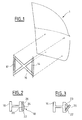
- FIG. 1 shows a schematic view of a window regulator 10 of this type.
- the window regulator 10 has two rails 12, 14 vertical and parallel to each other.
- a cable (not shown) is arranged in X between the rails 12, 14 and slides on these.
- the window regulator 10 further comprises a support 16 between the rails 12, 14.
- the rails 12, 14 are interconnected by the support 16.
- the support 16 keeps the rails 12, 14 in a vertical position and parallel to each other.
- Support 16a advantageously an X shape. It connects the upper end of each of the rails 12, 14 with the lower end of the other rail 12, 14. It thus provides rigidity sufficient for the window regulator to be fitted in a modular fashion on a door, motor vehicle for example.
- the support 16 also makes it possible to recover the forces caused by the cable tension during the operation of the window.
- the support 16 has a cross section in form of guide duct, in particular cable guide.
- the support 16 is of a tubular structure. It then not only guides the cable but also to protect it from attack by transport or mounting.
- the support is made of plastic, such as, for example, loaded polyamide fiberglass rigid enough to constitute the window regulator and sufficiently flexible to make up the clip.
- FIG. 2 shows the support 16 of window lifter rails according to the invention.
- the support 16 is shown without limitation with a section in H; the support can also have a U or tubular section.
- the support 16 comprises at at least one clip 18 for fixing at least one wire 20, the clip 18 being in one piece with the support 16.
- the clip 18 is a fixing means which clamps the wire 20 against the support 16 and holding in position.
- the clip forms a spring, in the sense that it is deformed elastically so that the wire can be inserted into the clip. When clip 18 is released, it tends to return to its rest position by pinching the wire.
- the clip 18 is in one piece with the support 16, in that it is integrated into the support 16.
- the clip and the support form a single piece. This has the advantage of ensuring that the presence of the clip on the support; indeed, when the clip is a piece added on the support, it could be forgotten when mounting the support on the door.
- Another advantage of the support according to the invention is to maintain in position the wire without damaging it.
- the clip 18 makes it possible to block several wires 20 along the support 16.
- the wires 20 can be electric wires supplying the peripherals installed on the vehicle door. These are, for example, wires supply of the courtesy light, of actuators actuating the mirrors, electric windows, central door closing, ... 20 wires can also be air passage pipes (as on the vehicle sold by the company Volkswagen under the Passat brand) or fluids such as control fluids Hydraulic.
- the support 16 can be obtained by a molding process.
- the process includes a step during which the clip is molded with the support 16.
- the advantage is that the molding of the clip is concomitant with the molding of the support and does not require an additional manufacturing step.
- the manufacture of the support is so simple and inexpensive.
- the clip 18 has at least one tab 22 articulated by one of its ends on the support 16.
- the tab is a narrow and elongated means. It can be flat or have a thickness.
- the clip 18 can be outside the guide duct formed by the support 16. This makes it easy to introduce the wires inside the clip 18.
- the articulation of the tab at one of its ends makes it possible to separate from the support the other end of the tab 22 by elastic deformation of the tab. This spacing frees a fixing housing between the tab and the support in which the 20 wires are introduced. When the wires are in place the free end is released and the tab 22 tends to return to its rest position. The wires 20 are then pinched against the support 16.
- the fixing of the wires is easy but is not, however, final. Indeed, the clip can be deformed again so as to be able to release the wires from the mounting housing between clip 18 and support 16.
- the tab 22 has a first concavity 24 oriented towards the support 16.
- the tab 22 is then curved and the housing between the tab 22 and the support 16 is enlarged. This allows a greater number of son.
- the tab 22 may also have, near its free end, a second concavity 26 oriented in a direction opposite to that of the first concavity 24.
- the second concavity 26 makes it possible to keep apart the free end of the tab 22 of the support 16.
- the advantage of the second concavity 26 is that it allows easily insert the wires 20 into the clip 18. For this, the wires 20 are plated against the support 16 near the free end of the tab 22 and translated into direction of the clip 18.
- the tab 22 is approaches the support 16 so as to restrict access to the first concavity. This prevents the wires introduced into the concavity from coming out.
- the tab 22, between the two concavities 24, 26, is in contact with the support 16. This makes it possible to prevent even better that the wires 20 come out of the clip 18, in particular when the vehicle is moving.
- the tab 22 is obtained by cutting the same wall of the support 16, in the form of a window. Three of the sides of tab 22 are cut in the wall of the support 16, the fourth side being the end at which the tab 22 is articulated on the support 16. This embodiment makes it possible to simplify the molding step during which the support without roughness is molded, and ability to cut clips 18 along support 16 at locations determined during fixing the wires 20 on the support 16.
- Figure 3 shows a section of the support 16 according to another mode of production.
- the clip 18 also has another tab. 23 articulated by one of its ends on the support 16.
- the tab 23 cooperates with the tab 22 for fixing the wires 20 along the tube.
- the tab 23 is articulated on the support 16 so as to form a housing the opening of which faces the tab 22.
- the free end of the tab 23 is directed towards the tab 22.
- the tab 23 has, for example, its free end in contact with the tab 22.
- the tabs 22, 23 form with the support 16 a housing for fixing the wires 20.
- the introduction of the wires 20 is performed by pressing the wires against tab 23 so that it flexes elastically towards the inside of the fixing housing.
- the sons are then translated towards the tab 22.
- the wires 20 are then fixed inside of the fixing housing.
- the fixation occurs, for example, as follows: the wires are held in place by pinching by the tab 22; if during transport, for example when the vehicle is moving, the wires emerge from the tab 22 due to vibrations, the wires are retained in the housing by the tab 23 in contact with the tab 22.
- This embodiment makes it easy to introduce the wires 20 into the housing, without them freeing themselves.
- the wires 20 can be removed from the fixing housing by manual action on one of the tabs 22, 23.
- the legs 22, 23 can have their free end in contact.
- This variant also has the advantage of being of simplified manufacture.
- the legs can be obtained during the molding step, but also by cutting the wall of the support 16.
- the support according to the invention has a plurality of clips 18 of fixation.
- the clips 18 are distributed along the support 16.
- the choice of the number and the location of the clips 18 is defined according to the number of wires and their usefulness.
- the plurality of clips 18 makes it possible to distribute the attachment of the wires along the support 16 and thus ensuring better fixing of the wires on the support.
- the window lifter support according to the invention can be installed so known in a vehicle door 1, such as a car, a truck, a coach, ...
- This door includes peripherals whose electrical wires are fixed by the clip.
- the support 16 can be attached and fixed to door 1 in a modular fashion, that is to say that the support can be made with a clip (s) and then fixed to the rails before being mounted on the door. It is then not necessary to add a fixing clip. according to the manufacturing method in which the clip includes a tab cut out from the wall of the support, it is then possible to define the number and the location of the clips function of the wires present in the door.
- the support according to the invention also makes it possible to support the peripherals mounted on the door. It is thus possible to fix the door handle, the speakers, the lock, ... on the support. Electrically powered devices have their supply wires fixed to the support via the clip.
- the present invention is not limited to the embodiments described by way of example; thus, the support can present a clip produced in the form of plate.
- the clip is then articulated on the support 16 along its length.
- the man of profession will determine the dimensions of the plate according to the number of wires and their usefulness.
- This form of clip has the same advantages as before; this shape also makes it possible to hold the wires at a greater length and to further improve the fixation.
Landscapes
- Engineering & Computer Science (AREA)
- Mechanical Engineering (AREA)
- Window Of Vehicle (AREA)
Abstract
Description
- figure 1, une vue schématique d'un lève-vitre ;
- figure 2, une section d'un support de rails de lève-vitre selon l'invention ;
- figure 3, une section d'un support selon un autre mode de réalisation.
Claims (16)
- Support (16) de rails de lève-vitre comprenant au moins un clip (18) de fixation d'au moins un fil (20), le clip (18) étant monobloc avec le support (16).
- Support selon la revendication 1, caractérisé en ce que le clip (18) comporte au moins une patte (22) articulée par une de ses extrémités sur le support (16).
- Support selon la revendication 2, caractérisé en ce que la patte (22) a une première concavité (24) orientée vers le support (16).
- Support selon la revendication 3, caractérisé en ce que la patte (22) a, à proximité de son extrémité libre, une deuxième concavité (26) orientée dans la direction contraire à la première concavité (24).
- Support selon la revendication 2, caractérisé en ce que le clip (18) comporte en outre une autre patte (23) articulée par une de ses extrémités sur le support (16).
- Support selon la revendication 5, caractérisé en ce qu'une patte (22) a son extrémité libre en contact avec l'autre patte (23).
- Support selon la revendication 5, caractérisé en ce que les pattes (22, 23) ont leur extrémité libre en contact.
- Support selon l'une des revendications précédentes, caractérisé en ce qu'il a une section transversale en forme de conduit de guidage.
- Support selon la revendication 8, caractérisé en ce que le clip (18) est à l'extérieur du conduit de guidage.
- Lève-vitre comprenant :un support (16) selon l'une des revendications 1 à 9, etdeux rails (12, 14) reliés entre eux par le support (16).
- Lève-vitre selon la revendication 10, caractérisé en ce que le support (16) maintient les rails (12, 14) parallèles entre eux.
- Lève-vitre selon la revendication 10 ou 11, caractérisé en ce que l'extrémité inférieure de chacun des rails (12, 14) est reliée par le support (16) à l'extrémité supérieure de l'autre rail.
- Lève-vitre selon la revendication 12, caractérisé en ce qu'il comprend en outre un câble coulissant dans les rails et dans le support (16).
- Porte de véhicule automobile comprenant un lève-vitre selon l'une des revendications 10 à 13.
- Porte selon la revendication 14, caractérisé en ce qu'elle comprend des périphériques dont les fils (20) électriques sont fixés par le clip (18).
- Procédé de fabrication d'un support selon l'une des revendications 1 à 9, le procédé comprenant une étape de moulage du support.
Applications Claiming Priority (2)
| Application Number | Priority Date | Filing Date | Title |
|---|---|---|---|
| FR0113737 | 2001-10-24 | ||
| FR0113737A FR2831227B1 (fr) | 2001-10-24 | 2001-10-24 | Leve-vitre |
Publications (2)
| Publication Number | Publication Date |
|---|---|
| EP1306253A1 true EP1306253A1 (fr) | 2003-05-02 |
| EP1306253B1 EP1306253B1 (fr) | 2005-04-20 |
Family
ID=8868658
Family Applications (1)
| Application Number | Title | Priority Date | Filing Date |
|---|---|---|---|
| EP20020292616 Expired - Lifetime EP1306253B1 (fr) | 2001-10-24 | 2002-10-22 | Lève-vitre |
Country Status (4)
| Country | Link |
|---|---|
| EP (1) | EP1306253B1 (fr) |
| DE (1) | DE60203772T2 (fr) |
| ES (1) | ES2241975T3 (fr) |
| FR (1) | FR2831227B1 (fr) |
Cited By (1)
| Publication number | Priority date | Publication date | Assignee | Title |
|---|---|---|---|---|
| EP1762684A3 (fr) * | 2005-09-12 | 2009-10-28 | Brose Fahrzeugteile GmbH & Co. Kommanditgesellschaft, Coburg | Lève-vitre de véhicule |
Families Citing this family (2)
| Publication number | Priority date | Publication date | Assignee | Title |
|---|---|---|---|---|
| DE102006017424B4 (de) * | 2006-04-13 | 2009-10-29 | Küster Automotive Door Systems GmbH | Einstellbare Befestigungsvorrichtung |
| JP6739476B2 (ja) * | 2018-06-29 | 2020-08-12 | 株式会社ハイレックスコーポレーション | ケーブル配索構造およびこれを用いた窓ガラス昇降装置 |
Citations (3)
| Publication number | Priority date | Publication date | Assignee | Title |
|---|---|---|---|---|
| US5735041A (en) * | 1996-07-24 | 1998-04-07 | United Technologies Automotive, Inc. | Wire harness assembly on trim panel |
| US5946858A (en) * | 1998-09-02 | 1999-09-07 | General Motors Corporation | Collapsible window lift module with diagonal structural link |
| DE19943338A1 (de) * | 1998-09-22 | 2000-03-30 | Kuester & Co Gmbh | Vorrichtung zum Heben und Senken einer Fensterscheibe in einem Kraftfahrzeug |
Family Cites Families (3)
| Publication number | Priority date | Publication date | Assignee | Title |
|---|---|---|---|---|
| DE19802478B4 (de) * | 1998-01-23 | 2005-11-03 | Brose Fahrzeugteile Gmbh & Co. Kommanditgesellschaft, Coburg | Kraftfahrzeugtür |
| JP3950233B2 (ja) * | 1998-06-17 | 2007-07-25 | 矢崎総業株式会社 | インストルメントパネルにおけるワイヤハーネスの固定構造及びインストルメントパネル |
| DE20020829U1 (de) * | 2000-11-30 | 2001-02-15 | Brose Fahrzeugteile GmbH & Co. KG, Coburg, 96450 Coburg | Aggregateträger |
-
2001
- 2001-10-24 FR FR0113737A patent/FR2831227B1/fr not_active Expired - Fee Related
-
2002
- 2002-10-22 EP EP20020292616 patent/EP1306253B1/fr not_active Expired - Lifetime
- 2002-10-22 ES ES02292616T patent/ES2241975T3/es not_active Expired - Lifetime
- 2002-10-22 DE DE2002603772 patent/DE60203772T2/de not_active Expired - Fee Related
Patent Citations (3)
| Publication number | Priority date | Publication date | Assignee | Title |
|---|---|---|---|---|
| US5735041A (en) * | 1996-07-24 | 1998-04-07 | United Technologies Automotive, Inc. | Wire harness assembly on trim panel |
| US5946858A (en) * | 1998-09-02 | 1999-09-07 | General Motors Corporation | Collapsible window lift module with diagonal structural link |
| DE19943338A1 (de) * | 1998-09-22 | 2000-03-30 | Kuester & Co Gmbh | Vorrichtung zum Heben und Senken einer Fensterscheibe in einem Kraftfahrzeug |
Cited By (1)
| Publication number | Priority date | Publication date | Assignee | Title |
|---|---|---|---|---|
| EP1762684A3 (fr) * | 2005-09-12 | 2009-10-28 | Brose Fahrzeugteile GmbH & Co. Kommanditgesellschaft, Coburg | Lève-vitre de véhicule |
Also Published As
| Publication number | Publication date |
|---|---|
| EP1306253B1 (fr) | 2005-04-20 |
| DE60203772D1 (de) | 2005-05-25 |
| DE60203772T2 (de) | 2006-03-09 |
| FR2831227B1 (fr) | 2004-10-22 |
| ES2241975T3 (es) | 2005-11-01 |
| FR2831227A1 (fr) | 2003-04-25 |
Similar Documents
| Publication | Publication Date | Title |
|---|---|---|
| EP1178175B1 (fr) | Système de positionnement et d'assemblage d'une vitre sur un lève-vitre | |
| EP0282389B1 (fr) | Dispositif de liaison électrique entre deux faisceaux de fils conducteurs et véhicule automobile équipé de ce dispositif | |
| EP2115837B1 (fr) | Dispositif de fixation pour chemin de cables en fils | |
| BE1004250A5 (fr) | Charniere de chassis de fenetre a battants. | |
| EP1147934A1 (fr) | Réservoir à carburant de véhicule automobile | |
| EP1912299B1 (fr) | Appareil électrique, destiné à être fixé sur un rail support, et procédé de montage correspondant | |
| FR2730521A1 (fr) | Patte de leve-vitre | |
| FR2815993A1 (fr) | Structure de support de vitre d'un regulateur de fenetre | |
| FR3113873A1 (fr) | Nappe de suspension pour siège de véhicule à support de guidage de câbles électriques | |
| WO2006084608A1 (fr) | Contact electrique femelle a lames de contact ressort | |
| FR2911730A1 (fr) | Dispositif d'alimentation en energie | |
| FR2876077A1 (fr) | Methode de montage d'un dispositif de commande interieur du mecanisme d'ouverture d'un ouvrant de vehicule automobile, piece intermediaire de prepositionnement utilise dans la methode, et ouvrant obtenu par cette methode | |
| EP1306253B1 (fr) | Lève-vitre | |
| EP0294254A1 (fr) | Vitrage mobile notamment pour véhicule automobile | |
| FR2789722A1 (fr) | Doublure interieure, et portiere ainsi equipee, comprenant un moyen pour limiter le deplacement d'une vitre au moins dans une direction | |
| EP1782985B2 (fr) | Cadre d'occultation pour pavillon vitré d'un véhicule automobile, et véhicule correspondant | |
| EP0878353B1 (fr) | Dispositif de pré-fixation d'un dispositif d'éclairage ou de signalisation sur une carrosserie de véhicule automobile | |
| FR2539793A1 (fr) | Boitier de serrure, destine notamment aux portes de vehicules automobiles | |
| FR2495680A1 (fr) | Organe d'appui incurve pour un leve-vitre a transmission par bowden | |
| FR2675958A1 (fr) | Dispositif de securite pour le branchement et le retrait d'une lampe a incandescence a culots lateraux. | |
| FR2901594A1 (fr) | Ratelier de support de cables, tuyauteries ou analogues, pour plancher d'habitacle de vehicule automobile | |
| FR2917452A1 (fr) | Systeme de liaison entre l'axe d'un volet roulant et une platine supportant l'axe | |
| FR2857511A1 (fr) | Borne de raccordement a obturateur de guidage rappele | |
| FR3003511A1 (fr) | Procede de montage d'un systeme de cables sur leve-vitre, leve-vitre et procedes de fabrication et de montage dans une porte de vehicule correspondants | |
| FR2649138A1 (fr) | Dispositif de fixation elastique d'un rail de chemin de fer sur son support |
Legal Events
| Date | Code | Title | Description |
|---|---|---|---|
| PUAI | Public reference made under article 153(3) epc to a published international application that has entered the european phase |
Free format text: ORIGINAL CODE: 0009012 |
|
| AK | Designated contracting states |
Designated state(s): AT BE BG CH CY CZ DE DK EE ES FI FR GB GR IE IT LI LU MC NL PT SE SK TR |
|
| AX | Request for extension of the european patent |
Extension state: AL LT LV MK RO SI |
|
| 17P | Request for examination filed |
Effective date: 20030927 |
|
| 17Q | First examination report despatched |
Effective date: 20031203 |
|
| AKX | Designation fees paid |
Designated state(s): DE ES FR IT |
|
| GRAP | Despatch of communication of intention to grant a patent |
Free format text: ORIGINAL CODE: EPIDOSNIGR1 |
|
| GRAS | Grant fee paid |
Free format text: ORIGINAL CODE: EPIDOSNIGR3 |
|
| GRAA | (expected) grant |
Free format text: ORIGINAL CODE: 0009210 |
|
| AK | Designated contracting states |
Kind code of ref document: B1 Designated state(s): DE ES FR IT |
|
| REG | Reference to a national code |
Ref country code: IE Ref legal event code: FG4D Free format text: LANGUAGE OF EP DOCUMENT: FRENCH |
|
| REF | Corresponds to: |
Ref document number: 60203772 Country of ref document: DE Date of ref document: 20050525 Kind code of ref document: P |
|
| PGFP | Annual fee paid to national office [announced via postgrant information from national office to epo] |
Ref country code: FR Payment date: 20051017 Year of fee payment: 4 |
|
| PGFP | Annual fee paid to national office [announced via postgrant information from national office to epo] |
Ref country code: ES Payment date: 20051026 Year of fee payment: 4 |
|
| REG | Reference to a national code |
Ref country code: ES Ref legal event code: FG2A Ref document number: 2241975 Country of ref document: ES Kind code of ref document: T3 |
|
| PGFP | Annual fee paid to national office [announced via postgrant information from national office to epo] |
Ref country code: DE Payment date: 20051130 Year of fee payment: 4 |
|
| PLBE | No opposition filed within time limit |
Free format text: ORIGINAL CODE: 0009261 |
|
| STAA | Information on the status of an ep patent application or granted ep patent |
Free format text: STATUS: NO OPPOSITION FILED WITHIN TIME LIMIT |
|
| 26N | No opposition filed |
Effective date: 20060123 |
|
| PGFP | Annual fee paid to national office [announced via postgrant information from national office to epo] |
Ref country code: IT Payment date: 20061031 Year of fee payment: 5 |
|
| PG25 | Lapsed in a contracting state [announced via postgrant information from national office to epo] |
Ref country code: DE Free format text: LAPSE BECAUSE OF NON-PAYMENT OF DUE FEES Effective date: 20070501 |
|
| REG | Reference to a national code |
Ref country code: FR Ref legal event code: ST Effective date: 20070629 |
|
| REG | Reference to a national code |
Ref country code: ES Ref legal event code: FD2A Effective date: 20061023 |
|
| PG25 | Lapsed in a contracting state [announced via postgrant information from national office to epo] |
Ref country code: FR Free format text: LAPSE BECAUSE OF NON-PAYMENT OF DUE FEES Effective date: 20061031 Ref country code: ES Free format text: LAPSE BECAUSE OF NON-PAYMENT OF DUE FEES Effective date: 20061023 |
|
| PG25 | Lapsed in a contracting state [announced via postgrant information from national office to epo] |
Ref country code: IT Free format text: LAPSE BECAUSE OF NON-PAYMENT OF DUE FEES Effective date: 20071022 |