EP1304848B1 - Flexible electronic message security mechanism - Google Patents
Flexible electronic message security mechanism Download PDFInfo
- Publication number
- EP1304848B1 EP1304848B1 EP02023650.1A EP02023650A EP1304848B1 EP 1304848 B1 EP1304848 B1 EP 1304848B1 EP 02023650 A EP02023650 A EP 02023650A EP 1304848 B1 EP1304848 B1 EP 1304848B1
- Authority
- EP
- European Patent Office
- Prior art keywords
- credential
- act
- electronic message
- computing system
- accordance
- Prior art date
- Legal status (The legal status is an assumption and is not a legal conclusion. Google has not performed a legal analysis and makes no representation as to the accuracy of the status listed.)
- Expired - Lifetime
Links
- 230000007246 mechanism Effects 0.000 title description 7
- 238000000034 method Methods 0.000 claims description 44
- 238000004891 communication Methods 0.000 description 9
- 230000003287 optical effect Effects 0.000 description 8
- 230000008901 benefit Effects 0.000 description 5
- 230000008569 process Effects 0.000 description 5
- 238000005516 engineering process Methods 0.000 description 4
- 230000006855 networking Effects 0.000 description 4
- 230000006870 function Effects 0.000 description 3
- 230000005055 memory storage Effects 0.000 description 3
- 230000005540 biological transmission Effects 0.000 description 2
- 230000002093 peripheral effect Effects 0.000 description 2
- 230000001010 compromised effect Effects 0.000 description 1
- 238000004590 computer program Methods 0.000 description 1
- 230000001419 dependent effect Effects 0.000 description 1
- 230000004044 response Effects 0.000 description 1
Images


Classifications
-
- H—ELECTRICITY
- H04—ELECTRIC COMMUNICATION TECHNIQUE
- H04L—TRANSMISSION OF DIGITAL INFORMATION, e.g. TELEGRAPHIC COMMUNICATION
- H04L63/00—Network architectures or network communication protocols for network security
- H04L63/12—Applying verification of the received information
- H04L63/123—Applying verification of the received information received data contents, e.g. message integrity
-
- H—ELECTRICITY
- H04—ELECTRIC COMMUNICATION TECHNIQUE
- H04L—TRANSMISSION OF DIGITAL INFORMATION, e.g. TELEGRAPHIC COMMUNICATION
- H04L51/00—User-to-user messaging in packet-switching networks, transmitted according to store-and-forward or real-time protocols, e.g. e-mail
-
- H—ELECTRICITY
- H04—ELECTRIC COMMUNICATION TECHNIQUE
- H04L—TRANSMISSION OF DIGITAL INFORMATION, e.g. TELEGRAPHIC COMMUNICATION
- H04L51/00—User-to-user messaging in packet-switching networks, transmitted according to store-and-forward or real-time protocols, e.g. e-mail
- H04L51/21—Monitoring or handling of messages
- H04L51/222—Monitoring or handling of messages using geographical location information, e.g. messages transmitted or received in proximity of a certain spot or area
-
- H—ELECTRICITY
- H04—ELECTRIC COMMUNICATION TECHNIQUE
- H04L—TRANSMISSION OF DIGITAL INFORMATION, e.g. TELEGRAPHIC COMMUNICATION
- H04L63/00—Network architectures or network communication protocols for network security
- H04L63/12—Applying verification of the received information
- H04L63/126—Applying verification of the received information the source of the received data
-
- H—ELECTRICITY
- H04—ELECTRIC COMMUNICATION TECHNIQUE
- H04L—TRANSMISSION OF DIGITAL INFORMATION, e.g. TELEGRAPHIC COMMUNICATION
- H04L67/00—Network arrangements or protocols for supporting network services or applications
- H04L67/01—Protocols
- H04L67/02—Protocols based on web technology, e.g. hypertext transfer protocol [HTTP]
-
- H—ELECTRICITY
- H04—ELECTRIC COMMUNICATION TECHNIQUE
- H04L—TRANSMISSION OF DIGITAL INFORMATION, e.g. TELEGRAPHIC COMMUNICATION
- H04L67/00—Network arrangements or protocols for supporting network services or applications
- H04L67/50—Network services
- H04L67/56—Provisioning of proxy services
-
- H—ELECTRICITY
- H04—ELECTRIC COMMUNICATION TECHNIQUE
- H04L—TRANSMISSION OF DIGITAL INFORMATION, e.g. TELEGRAPHIC COMMUNICATION
- H04L63/00—Network architectures or network communication protocols for network security
- H04L63/04—Network architectures or network communication protocols for network security for providing a confidential data exchange among entities communicating through data packet networks
- H04L63/0428—Network architectures or network communication protocols for network security for providing a confidential data exchange among entities communicating through data packet networks wherein the data content is protected, e.g. by encrypting or encapsulating the payload
-
- H—ELECTRICITY
- H04—ELECTRIC COMMUNICATION TECHNIQUE
- H04L—TRANSMISSION OF DIGITAL INFORMATION, e.g. TELEGRAPHIC COMMUNICATION
- H04L67/00—Network arrangements or protocols for supporting network services or applications
- H04L67/50—Network services
- H04L67/56—Provisioning of proxy services
- H04L67/561—Adding application-functional data or data for application control, e.g. adding metadata
Description
- The present invention relates to electronic messaging, and more particularly, to mechanisms for allowing more flexible use of security mechanisms when communicating using electronic messages.
- Computing technology has transformed the way we work and play. Modem computer networking technologies and infrastructures allow for different applications and users to communicate data electronically even over vast distances relatively quickly using readily-available computing systems. Such computing systems may include, for example, desktop computers, laptop computers, Personal Digital Assistants (PDAs), digital telephones, or the like.
- Currently, computing systems are so interconnected that one computing system is literally capable of communicating with any one of many millions of other computing systems spread throughout the globe. This is useful as we are now able to communicate more readily. However, this high level of interconnectivity also exposes us to security problems. For example, often it is necessary to verify that a computing device or associated user is truly the same entity that they purport to be in a process called authentication. Also, it is often important to validate the integrity of an electronic message to be sure that the electronic message has not been compromised during transmission.
- Improvements in security mechanisms are of significant benefit since breaches in security can cause much harm, financial and otherwise, to entities who rightfully desire secure electronic communications. The principles of the present invention improve security over conventional security technologies as will be described in further detail below.
WO 97/50205
EP1 111 559 A2 relates to secure electronic transactions made over public networks such as the internet. An electronic message for transmission over a network is created by encrypting a first component with a first crypto-key, which is associated with a first network entity, such that the encrypted first component can be decrypted by only the first network entity. A second component, which is different than the first component, is encrypted with a second crypto key, which is associated with a second network entity, such that the encrypted second component can also be decrypted by the first network entity. The encrypted first and second components are combined to create the electronic message. - It is the object of the invention to provide a flexible and reliable security mechanism when communicating using electronic messages, without the need of sharing a public/private key pair between the parties. In particular, the present invention provides means to determine whether tampering of an electronic message may have occurred. Preferred embodiments are specified in the dependent claims.
- The principles of the present invention relate to mechanisms for providing reliable and flexible security mechanisms when communicating using electronic messages. The electronic message may have multiple different types of credentials. The electronic message may include the encoding format and type of each of the credentials thus allowing for convenient access of the credential by either the recipient computing system, or by an intermediary computing system. The electronic message may also include multiple signatures that were each signed using a different credential. The signatures may each have a reference to a location even external to the electronic message. The recipient computing system may evaluate the external credential against the signature to determining whether tampering of the electronic message may have occurred.
- Additional features and advantages of the invention will be set forth in the description which follows, and in part will be obvious from the description, or may be learned by the practice of the invention. The features and advantages of the invention may be realized and obtained by means of the instruments and combinations particularly pointed out in the appended claims. These and other features of the present invention will become more fully apparent from the following description and appended claims, or may be learned by the practice of the invention as set forth hereinafter.
- In order to describe the manner in which the above-recited and other advantages and features of the invention can be obtained, a more particular description of the invention briefly described above will be rendered by reference to specific embodiments thereof which are illustrated in the appended drawings. Understanding that these drawings depict only typical embodiments of the invention and are not therefore to be considered to be limiting of its scope, the invention will be described and explained with additional specificity and detail through the use of the accompanying drawings in which:
-
Figure 1 illustrates a suitable computing system in which the principles of the present invention may be employed; -
Figure 2 illustrates a flowchart of a method for securely transmitting an electronic message in accordance with the principles of the present invention; -
Figure 3 illustrates a data structure of an electronic message having multiple different types of credentials in the header of the electronic message in accordance with the principles of the present invention; -
Figure 4A illustrates a network environment in which multiple different credentials are used to identify a source computing system to a particular recipient computing system in a model called herein the "multiple credential - single recipient model"; -
Figure 4B illustrates a network environment in which different credentials in the electronic message may be used to identify the source computing system to an intermediary computing system and to identify the source computing device to a recipient computing system in a model called herein the "serial credential model"; -
Figure 4C illustrates a network environment in which different credentials in the electronic message may be used to identify the source computing system to different recipient computing systems in a model called herein the "parallel credential model"; -
Figure 4D illustrates a network environment which combines all of the models ofFigures 4A, 4B and4C ; and -
Figure 5 illustrates a credential semantic inheritance tree in accordance with the principles of the present invention. - The principles of the present invention relate to methods, systems, computer program products, and data structures that allow more secure communications of an electronic message.
- Multiple different credentials and/or signatures based on different credentials may be included in a header portion of a single electronic message. These different signatures and/or credentials may be used by different recipient computing systems, by a single recipient computing system, or even by different computing systems along a routing path of the electronic message.
- The electronic message may include an identification of an encoding algorithm and the type of credential included in the electronic message. Accordingly, multiple different credentials may be included that have different encoding. The recipient computing system may decode and process the credential as appropriate given the identification of the encoding algorithm and the type of credential.
- Also, the electronic message may include a pointer that references a credential that is accessible to the recipient computing system, either within the same electronic message, or from some other location. The recipient computing system may then compare the referenced credentials from the credentials used to generate the signature. If a match occurs, then the data signed can be associated with the credentials. Accordingly, the integrity of any statement made in the credentials such as identity, rights, and so forth, may be verified.
- Embodiments within the scope of the present invention include computer-readable media for carrying or having computer-executable instructions or data structures stored thereon. Such computer-readable media can be any available media which can be accessed by a general purpose or special purpose computer. By way of example, and not limitation, such computer-readable media can comprise physical computer-readable media such as RAM, ROM, EEPROM, CD-ROM or other optical disk storage, magnetic disk storage or other magnetic storage devices, or any other medium which can be used to carry or store desired program code means in the form of computer-executable instructions or data structures and which can be accessed by a general purpose or special purpose computer.
- When information is transferred or provided over a network or another communications connection (either hardwired, wireless, or a combination of hardwired or wireless) to a computer, the computer properly views the connection as a computer-readable medium. Thus, any such a connection is properly termed a computer-readable medium. Combinations of the above should also be included within the scope of computer-readable media. Computer-executable instructions comprise, for example, instructions and data which cause a general purpose computer, special purpose computer, or special purpose processing device to perform a certain function or group of functions.
-
Figure 1 and the following discussion are intended to provide a brief, general description of a suitable computing environment in which the invention may be implemented. Although not required, the invention will be described in the general context of computer-executable instructions, such as program modules, being executed by computers in network environments. Generally, program modules include routines, programs, objects, components, data structures, and the like, that perform particular tasks or implement particular abstract data types. - Those skilled in the art will appreciate that the invention may be practiced in network computing environments with many types of computer system configurations, including personal computers, hand-held devices, multi-processor systems, microprocessor-based or programmable consumer electronics, network PCs, minicomputers, mainframe computers, arid the like. The invention may also be practiced in distributed computing environments where tasks are performed by local and remote processing devices that are linked (either by hardwired links, wireless links, or by a combination of hardwired or wireless links) through a communications network. In a distributed computing environment, program modules may be located in both local and remote memory storage devices.
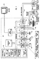
- With reference to
Figure 1 , an exemplary system for implementing the invention includes a general purpose computing device in the form of aconventional computer 120, including aprocessing unit 121, asystem memory 122, and asystem bus 123 that couples various system components including thesystem memory 122 to theprocessing unit 121. Throughout this description, element numbers begin with the same number as the figure in which the corresponding elements were first introduced. For example, all of the element numbers inFigure 1 are numbered in the 100's while the element numbers inFigure 2 are number in the 200's, and so forth. - The
system bus 123 may be any of several types of bus structures including a memory bus or memory controller, a peripheral bus, and a local bus using any of a variety of bus architectures. The system memory includes read only memory (ROM) 124 and random access memory (RAM) 125. A basic, input/output system (BIOS) 126, containing the basic routines that help transfer information between elements within thecomputer 120, such as during start-up, may be stored inROM 124. - The
computer 120 may also include a magnetichard disk drive 127 for reading from and writing to a magnetichard disk 139, amagnetic disk drive 128 for reading from or writing to a removablemagnetic disk 129, and anoptical disk drive 130 for reading from or writing to removable optical disk 131 such as a CD-ROM or other optical media. The magnetichard disk drive 127,magnetic disk drive 128, andoptical disk drive 130 are connected to thesystem bus 123 by a harddisk drive interface 132, a magnetic disk drive-interface 133, and anoptical drive interface 134, respectively. The drives and their associated computer-readable media provide nonvolatile storage of computer-executable instructions, data structures, program modules and other data for thecomputer 120. Although the exemplary environment described herein employs a magnetichard disk 139, a removablemagnetic disk 129 and a removable optical disk 131, other types of computer readable media for storing data can be used, including magnetic cassettes, flash memory cards, digital video disks, Bernoulli cartridges, RAMs, ROMs, and the like. - Program code means comprising one or more program modules may be stored on the
hard disk 139,magnetic disk 129, optical disk 131,ROM 124 orRAM 125, including anoperating system 135, one or more applications programs 136,other program modules 137, andprogram data 138. A user may enter commands and information into thecomputer 120 throughkeyboard 140, pointingdevice 142, or other input devices (not shown), such as a microphone, joy stick, game pad, satellite dish, scanner, or the like. These and other input devices are often connected to theprocessing unit 121 through a serial port interface 46 coupled tosystem bus 123. Alternatively, the input devices may be connected by other interfaces, such as a parallel port, a game port or a universal serial bus (USB). Amonitor 147 or another display device is also connected tosystem bus 123 via an interface, such asvideo adapter 148. In addition to the monitor, personal computers typically include other peripheral output devices (not shown), such as speakers and printers. - The
computer 120 may operate in a networked environment using logical connections to one or more remote computers, such asremote computers Remote computers computer 120, although onlymemory storage devices application programs Figure 1 . The logical connections depicted inFigure 1 include a local area network (LAN) 151 and a wide area network (WAN) 152 that are presented here by way of example and not limitation. Such networking environments are commonplace in office-wide or enterprise-wide computer networks, intranets and the Internet. - When used in a LAN networking environment, the
computer 120 is connected to thelocal network 151 through a network interface oradapter 153. When used in a WAN networking environment, thecomputer 120 may include amodem 154, a wireless link, or other means for establishing communications over thewide area network 152, such as the Internet. Themodem 154, which may be internal or external, is connected to thesystem bus 123 via theserial port interface 146. In a networked environment, program modules depicted relative to thecomputer 120, or portions thereof, may be stored in the remote memory storage device. It will be appreciated that the network connections shown are exemplary and other means of establishing communications overwide area network 152 may be used. - While
Figure 1 illustrates an example of a computing system that may implement the principles of the present invention, any computing system may implement the features of the present invention. In the description and in the claims, a "computing system" is defined as any hardware component or components that are capable of using software to perform one or more functions. Examples of computing systems include desktop computers, laptop computers, Personal Digital Assistants (PDAs), telephones, or any other system or device that has processing capability. -
Figure 2 illustrates a method 200 for performing electronic messaging in a secure manner. Some of the acts and the step of the method 200 are performed by a sender computing system that sends an electronic message. Those acts and that step are generally listed in the left column ofFigure 2 under the heading "SENDER". Other acts of the method 200 are performed be a receiver computing system that receives the electronic message. Those acts are generally listed in the right column ofFigure 2 under the heading "RECEIVER". - The method 200 includes a functional, result-oriented step for constructing an electronic message so as to provide increased security (step 210). This functional, result-oriented step may include any corresponding acts for accomplishing this result. However, in the illustrated embodiment, the
step 210 includes correspondingacts 211 through 218. An example electronic message data structure is illustrated inFigure 3 aselectronic message 300. The method ofFigure 2 will be described with frequent reference to the electronic message data structure ofFigure 3 . - The method 200 includes an act of designating at least one destination address in the electronic message (act 211). The destination address corresponds to one or more recipient computing systems. Referring to
Figure 3 , the electronic message includes aheader field 310 and abody field 330. Thebody field 330 may contain the content of the information desired to be communicated to the recipient(s), while theheader field 310 contains information that facilitates proper and secure transport and processing of the electronic message. Theheader field 310 includes adestination address field 311 that contains the destination address or addresses of one or more desired recipients of the electronic message. - The
method 300 then includes an act of including one or more security tokens in a header portion of the electronic message (act 212). The one of more security tokens may be, for example, one or more signatures. For example, theheader field 310 includes afirst signature 312, a possiblesecond signature 313, and potentially other signatures 314. Thefirst signature 312 is oval-shaped to represent that the first signature may have been signed using acorresponding credential 315, which is also represented as being oval-shaped. Thesecond signature 313 is trapezoidal-shaped to represent that the second signature may have been signed using a differentcorresponding credential 316, which is also represented as being trapezoidal-shaped. - In addition to including the signatures (act 212) or other security tokens in the electronic message, the
method 300 includes an act of encoding one of more credentials (act 213), and then the act of including the one or more encoded credentials in the electronic message (act 214). In some cases, the credential(s) included in the electronic message may not be encoded at all thus eliminatingact 213. In other cases, a credential will not be included in the electronic message either thus eliminatingact 214. For example, there may not be any cause for including a credential if there is a reference to an associated credential field described below where the credential may be external to the electronic message. - The credentials may be, for example, any item of information that helps to identify and/or authenticate the credential provider. One type of credential is a license, which contains a set of related assertions signed by an authority. Some assertions may be about keys that may be used to sign and/or encrypt messages. Example licenses include X.509 certificates and Kerberos tickets. The owner of a license is a principle entity that can use the license authoritatively. Specifically, the principle has the knowledge necessary to apply the cryptographic keys located in the attached license or licenses attached therein. In
Figure 3 , the included credentials are represented byfirst credential 315,second credential 316, and other credentials 317. - The method 200 also includes an act of including, in the header portion, an identification of an encoding format of the credential(s) (act 215). This identification is represented in
Figure 3 for thefirst credential 315 by the encodingformat field 318A. The identification is represented inFigure 3 for thesecond credential 316 by the encodingformat field 318B. Themethod 300 also includes an act of including, in the header portion, an identification of a type of the credential (act 216). For example, the type of credential may be an X.509 certificate or a Kerberos ticket. The identification of the type of credential is represented inFigure 3 for thefirst credential 315 by thecredential type field 319A, and for thesecond credential 316 by thecredential type field 319B. - In this example, there is an identification of the encoding format and a credential type for each of the credentials included in the electronic message, although this is not necessary. For example, in cases in which the encoding format is the same for all of the credentials in the electronic message, the encoding format may be listed in just one portion of the electronic message. Similarly, if the credential type is the same for all of the credentials in the electronic message, the credential format may just be listed once. In addition, if a particular credential has a default encoding format (and/or credential type), then the particular encoding format (and/or credential type) need not be expressly included for that credential.
- Also, the identification of the encoding format and credential type are illustrated as being included in the corresponding credential field. If these fields are included in the corresponding credential field, acts 215 and 216 would occur concurrently with
act 213 for that credential. However, the encoding format and type field may instead just be associated with the corresponding credential field. - The
method 300 also includes an act of generating a reference indicating where a credential associated with the signature may be found (act 217), and including the reference in the header portion of the electronic message (act 218). The reference is represented inFigure 3 for thefirst signature 312 by the reference to associated credential field 320A, and for thesecond signature 313 by the reference to associated credential field 320B. While the reference may include a reference to a position internal to the electronic message (e.g., credential fields 316 and 317), the reference may also be a Uniform Resource Locator (URL) that identifies a location external to the electronic message where the associated credential may be found. - The sending computing system then transmits the electronic message to one or more recipient computing system (act 219), which then receive the electronic message (act 220). The electronic message may contain multiple different signatures that were generated using multiple different kinds of credentials. The recipient computing system may then select one of a multiple signatures included in a header portion of the electronic message (act 221), and then reads that electronic signature from the electronic message (act 222). Accordingly, the recipient computing system may choose one, some, or all of the included signatures depending one which one the recipient computing system is configured to process and trust.
- The ability of the
electronic message 300 to contain multiple credentials of different types allows for several novel network security configurations. For example,Figure 4A illustrates anetwork environment 400A in which multiple different credentials are used to identify asource computing system 401A to a particularrecipient computing system 411A in a model called herein the "multiple credential - single recipient model". In this model, a singlerecipient computing system 411A uses twodifferent credentials source computing system 401A. The credentials are illustrated inFigures. 4A through 4D as having different shapes to emphasize that the credentials may be of different types. -
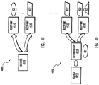
Figure 4B illustrates anetwork environment 400B in which different credentials in the electronic message may be used to identify asource computing system 400B to an intermediary computing system 411B and to identify the source computing device 401B to arecipient computing system 412B in a model called herein the "serial credential model". In the illustratedserial credential model 400B, the intermediary computing system 411B uses thecredential 421, while therecipient computing system 412B uses thecredential 422. -
Figure 4C illustrates anetwork environment 400C in which different credentials in the electronic message may be used to identify the source computing device to differentrecipient computing devices parallel credential model 400C, therecipient computing system 411C uses thecredential 421, while therecipient computing system 412C uses thecredential 422. - There are various combinations of each of the models of
Figure 4A through 4C that male a practically limitless variety of network configurations. For example,Figure 4D illustrates a network environment 400D which combines all of the models ofFigures 4A, 4B and4C in one of many possible ways. In the environment 400D, the electronic message includes threecredentials Credential 423 is different thancredentials intermediary computing system 411C usescredential 421,recipient computing system 412D usescredential 422, and recipient computing system 413D usescredentials - Returning to
Figure 3 , the receiving computing system also may read, the reference that indicates where an associated credential may be found (act 223), use that reference to find the credential (act 224), and then determine if the credential corresponds with the electronic signature, (act 225). If there the referenced credential corresponds to the signature, then the data signed can be associated with the credential. Accordingly, the integrity of any statements made in the credentials such as identity, rights, and so forth, may be more assured, especially if the referenced credential was external to the electronic message and thus not subject to the same tampering instances that the electronic message may be subject to. - In one embodiment, the
electronic message 300 may be a Simple Object Access Protocol (SOAP) envelope although this is not required. The two provisional patent applications previously incorporated herein by reference provide several examples of SOAP envelopes which incorporate various aspects of the present invention. The following SOAP envelope is a code example of one specific embodiment of the data structure of theelectronic message 300. The code example is represented in extensible Markup Language (XML) version 1.0. Line numbering has been added for clarity in explaining the structure of the code example. Although this code example shows one specific implementation, there are a vast variety of different implementations that may employ the principles of the present invention. For example, although this example illustrates the use of headers hierarchically structured in a certain way and having particular header uses, other embodiments may have a different hierarchy and usage of headers without departing from the scope of the principles of the present invention.


-
Line 1 defines the XML version that the SOAP envelope follows as well as the encoding format for the SOAP envelope as a whole. - Lines 2 through 80 define a SOAP envelope that includes two different credentials, two different signatures signed using the credentials, and references to the credentials for each of the signatures. Also, the encoding type and format type of each of the credentials is specified.
- Lines 3 through 5 define global namespace abbreviations used throughout the SOAP envelope. It is standard practice to specify namespace abbreviation in this portion of the SOAP envelope. These namespace abbreviations correspond to a namespace that defines a standard for how particular elements to which the namespace applies are to be interpreted.
- Lines 77 though 79 represent the body of the SOAP envelope and is an example of the
body field 330 ofFigure 3 . Note that the actual body content is replaced with the capitalized term "BODY". Capitalized terms are used throughout the code example to replace actual content whose value is not specifically included in the code example and the value is not important to the principles of the present invention. For example, the term "BODY" in line 78 could be any content without affecting the principles of the present invention. - Lines 6 though 76 represent the header information for the SOAP envelope and is an example of the
header field 310 ofFigure 3 . - Lines 7 through 9 express the path that the electronic message is to take. Intermediary computing systems such as intermediary computing system 411B of
Figure 4B may be specified in this section. - Lines 10 through 25 define a unique SOAP header called "credentials". This header may include several different credential types. The encoding format and type of the credential may also be specified in this header.
- For instance, lines 12 through 18 contain a binary license (see line 17) called "X509License" (see line 16), which is identified as being an X.509 certificate (see line 14), and which is identified as being encoded using base64binary encoding (see line 15). Line 14 is an example of the
credential type field 319A ofFigure 3 . Line 15 is an example of the encodingformat field 318A ofFigure 3 . Line 17 is an example of thefirst credential field 315 ofFigure 3 . - Also, lines 19 through 24 contain a binary credential (see line 23) called "BinaryCredential" (see line 22), which is identified as being in a binary credential format (see line 20), and which is identified as being encoded also using base64binary encoding (see line 21). Line 20 is an example of the
credential type field 319B ofFigure 3 . Line 21 is an example of the encodingformat field 318B ofFigure 3 . Line 23 is an example of thesecond credential field 316 ofFigure 3 . - Lines 26 through 75 define an "integrity" header that contains two signatures, each having a reference location to find a corresponding credential that may be used to verify the integrity of the electronic message (i.e., that the electronic message was sent by the signer of the signature, and that the electronic message has not been altered in transit).
- In particular, a first signature element is referenced from lines 27 through 50, with the second signature element being referenced from lines 51 through 74. Each signature element follows the schema defined by XML digital signature in accordance with the "http://www.w3.org/2000/09/xmldsig#" namespace. However, that KeyInfo child element within each XML digital signature includes a "LicenseLocation" element that references the location of a license (or other credential) that may be used to verify the integrity of the electronic message.
- The first signature element includes a "SignedInfo" element from lines 28 through 43 which defines canonicalization methods, digest algorithms, and various transforms that apply to the signature. The first signature value is included at line 45 and is an example of the
first signature field 312 ofFigure 3 . The license location specified at line 48 is an example of the reference to associated credential field 320A ofFigure 3 . - The second signature element is similar to the first signature element except that the second signature value is at line 69 and represents an example of
second signature field 313 ofFigure 3 , while the license location is specified at line 72 and represents an example of the reference to associated credential field 320B ofFigure 3 . - Accordingly, the principles of the present invention allow for the communication of multiple different credentials in a single electronic message. In addition, the reference to an associated credential allows for the integrity of electronic messages to be verified.
- In the above code example, there are two different credentials included in the electronic message, a binary license and a binary credential. These credential types may be abstractly structured in an inheritance tree. A hierarchically-structured credential semantics inheritance tree that includes these credential types is illustrates as
tree 500 inFigure 5 .. - The
tree 500 includes an abstractcredential data type 501 at its base. The abstract credential is structured in accordance with aschema 501A and has handling rules 501B. Theschema 501A describes the basic structure of the abstract credential data type. The handling rules 501B describe how to handle the abstract credential. - One of the first-tier branches of the
tree 500 is an abstractlicense data type 511, which includes anextended schema 511 A and extended handling rules 511B. The schema and the handling rules from parent nodes in thetree 500 may be inherited by the child nodes. In other words, theschema 511 A of the abstract license may reflect theschema 501A of the abstract credential with some specified extensions. Also, the handling rules 511B may represent further handling rules in addition to the handling rules 501B specified at the abstract credential data type. - Another of the first-tier branches of the
tree 500 is a binarycredential data type 512 that includesschema 512A and handling rules 512B. A second tier-branch of the tree includesbinary license 521 havingschema 521A andhandling rules 521B. Thetree 500 may be further expanded by defining a schema that extends on the schema of a parent node, and/or by defining further handling rules in addition to those provided for a parent node. - When determining how to structure a binary license for example, the source computing system would use the
schema 521A. If theschema 521A represented incremental structural changes rather than a complete structural definition, the source computing system may also consult the schema ofancestral data types schema 521A to determine how to parse the binary license, along with the handling rules 521 B to determine how to treat the binary license in terms of how to process the binary license and what authorities to grant in response to the binary license. The handling rules 521B may represent incremental handling rules in which case the ancestral handling rules 511 B and 501B may also be consulted to determine proper handling. Thetree 500 may be stored at both the source computing system and the recipient computing system so as to ensure consistent treatment of credentials.
Claims (24)
- In a network environment that includes a plurality of computing systems capable of communicating using electronic messaging (300), a method for a source computing system constructing an electronic message, the method comprising the following:an act of including one or more electronic signatures in a header (310) portion of an electronic message, the electronic signatures generated by a user;an act of generating (217) a reference indicating where a credential associated with the electronic signature may be found; wherein the reference indicates that the associated credential may be found at a location that is external to the electronic message;an act of including (218) the reference in the header portion of the electronic message.an act of designating at least one destination address in the electronic message, the destination address corresponding to one or more recipient computing devices.; an act of transmitting the electronic message to the one or more recipient computing devices.
- The method of claim 1, wherein a first electronic signature (312) being at least derived from a first credential (315) of a first credential type (319A) and a second electronic signature (313) being at least derived from a second credential (316) of a second credential type (319B), are included in the header portion of the electronic message.
- The method in accordance with Claim 2, further comprising the following:an act of transmitting the electronic message with the first signature and the second signature in the header portion to the one or more recipient computing devices.
- The method in accordance with Claim 2, further comprising the following:an act of including the first credential in the electronic message.
- The method in accordance with Claim 2, further comprising the following:an act of including the second credential in the electronic message.
- The method in accordance with Claim 2, further comprising:an act of designating an intermediary address that corresponds to an intermediary computing device.
- The method in accordance with Claim 2, further comprising
an act of encoding the first credential;
an act of including, in the header portion, an identification, of an encoding format of the first credential; and
an act of including, in the header portion, an identification of a type of the security token. - The method in accordance with claim 1, further comprising the following:an act of encoding a credential, that identifies the source computing device;an act of including the credential in a header portion of an electronic message;an act of including, in the header portion, an identification of an encoding format of the credential; andan act of including, in the header portion, an identification of a type of the credential.
- A method in accordance with Claim 8, wherein the credential is a license.
- A method in accordance with Claim 9, wherein the credential is in a binary format, wherein the act of including, in the header portion, an identification of a type of the credential comprises an act of including, in the header portion, an indication that the credential has the binary format.
- A methods in accordance with Claim 8, wherein the credential is in a binary format, wherein the act of including, in the header portion, an identification of a type of the credential comprises an act of including, in the header portion, an indication that the credential has the binary format.
- A computer-readable medium storing computer executable instructions that, when carried out by a processor, cause the processor to perform the method of one of claims 1 to 11.
- A computer system comprising means adapted to perform the method of one of claims 1 to 11.
- In a network environment that includes a plurality of computing systems capable of communicating using electronic messaging, a method for one or more a recipient computing systems to verify the identity of a sender of an electronic message, the method comprising the following:an act of receiving (220) the electronic message;an act of reading (222) an electronic signature from a header portion of the electronic message, the electronic signature generated by a user;an act of reading a reference from the header portion; wherein the reference indicates that the associated credential may be found at a location that is external to the electronic message;an act of using the reference (224) to find the credential; andan act of determining (225) if the credential corresponds with the electronic signature.
- The method in accordance with Claim 14, wherein the electronic message contains a first credential and a second credential and it is received by at least a first and a second recipient computing system.
- The method in accordance with Claim 15, further comprising the following:an act in which the first recipient computing system uses the first credential to identify the source computing system; andan act in which the second recipient computing system uses the second credential to identify the source computing system.
- The method in accordance with Claim 14, wherein the electronic message contains a first credential and a second credential and it is received by at least a first recipient computing system.
- The method in accordance with Claim 17, further comprising the following:an act in which the first recipient computing system uses both of the first credential and the second credential to identify the source computing system.
- The method in accordance with Claim 14, wherein the electronic message contains a first credential and a second credential and it is received by at least a first recipient computing system the electronic message also traversing through an intermediary computing system.
- The method in accordance with Claim 19, further comprising the following:an act in which the first recipient computing system uses the first credential to identify the source computing system; andan act in which the intermediary computing system uses the second credential to identify the source computing system.
- A computer readable medium storing computer-executable instructions that, when carried out by a processor, cause the processor to perform the method of one of claims 16 to 20.
- The computer-readable medium in accordance with claim 21, further comprising:computer-executable instructions for detecting the receipt of an electronic message;computer-executable instructions for reading a credential from the electronic message;computer-executable instructions for determining how to handle the credential and the electronic message based on a position of the credential within a logical hierarchical tree of credentials.computer-executable instructions for handling the credential and the electronic message as determined.
- The computer-readable medium in accordance with claim 21, further comprising:computer-executable instructions for consulting handling rules of at least one ancestral credential in the logical hierarchical tree;computer-executable instructions for consulting extended handling rules specific to the credential included in the electronic message; andcomputer-executable instruction for determining handling rules for the credential included in the electronic message by using the handling rules for the at least one ancestral credential as well as the extended handling rules specific to the credential included in the electronic message.
- A computing system comprising means adapted to perform the method of one of claims 16 to 20.
Applications Claiming Priority (4)
| Application Number | Priority Date | Filing Date | Title |
|---|---|---|---|
| US34637001P | 2001-10-19 | 2001-10-19 | |
| US346370P | 2001-10-19 | ||
| US219898 | 2002-08-14 | ||
| US10/219,898 US7293283B2 (en) | 2001-10-16 | 2002-08-14 | Flexible electronic message security mechanism |
Publications (3)
| Publication Number | Publication Date |
|---|---|
| EP1304848A2 EP1304848A2 (en) | 2003-04-23 |
| EP1304848A3 EP1304848A3 (en) | 2010-09-22 |
| EP1304848B1 true EP1304848B1 (en) | 2017-05-17 |
Family
ID=26914377
Family Applications (1)
| Application Number | Title | Priority Date | Filing Date |
|---|---|---|---|
| EP02023650.1A Expired - Lifetime EP1304848B1 (en) | 2001-10-19 | 2002-10-21 | Flexible electronic message security mechanism |
Country Status (4)
| Country | Link |
|---|---|
| US (1) | US7293283B2 (en) |
| EP (1) | EP1304848B1 (en) |
| ES (1) | ES2637251T3 (en) |
| HK (1) | HK1054639B (en) |
Families Citing this family (23)
| Publication number | Priority date | Publication date | Assignee | Title |
|---|---|---|---|---|
| US8015204B2 (en) | 2001-10-16 | 2011-09-06 | Microsoft Corporation | Scoped access control metadata element |
| EP1303097A3 (en) | 2001-10-16 | 2005-11-30 | Microsoft Corporation | Virtual distributed security system |
| US7676540B2 (en) | 2001-10-16 | 2010-03-09 | Microsoft Corporation | Scoped referral statements |
| US7194553B2 (en) | 2001-10-16 | 2007-03-20 | Microsoft Corporation | Resolving virtual network names |
| US7899047B2 (en) | 2001-11-27 | 2011-03-01 | Microsoft Corporation | Virtual network with adaptive dispatcher |
| US7546452B2 (en) * | 2002-08-20 | 2009-06-09 | Intel Corporation | Hardware-based credential management |
| US7457955B2 (en) * | 2004-01-14 | 2008-11-25 | Brandmail Solutions, Inc. | Method and apparatus for trusted branded email |
| US7676846B2 (en) * | 2004-02-13 | 2010-03-09 | Microsoft Corporation | Binding content to an entity |
| US8782405B2 (en) * | 2004-03-18 | 2014-07-15 | International Business Machines Corporation | Providing transaction-level security |
| US20070006294A1 (en) * | 2005-06-30 | 2007-01-04 | Hunter G K | Secure flow control for a data flow in a computer and data flow in a computer network |
| US8060747B1 (en) | 2005-09-12 | 2011-11-15 | Microsoft Corporation | Digital signatures for embedded code |
| US7814328B1 (en) * | 2005-09-12 | 2010-10-12 | Microsoft Corporation | Digital signatures for embedded code |
| US8205087B2 (en) * | 2006-02-27 | 2012-06-19 | Microsoft Corporation | Tool for digitally signing multiple documents |
| US8190902B2 (en) * | 2006-02-27 | 2012-05-29 | Microsoft Corporation | Techniques for digital signature formation and verification |
| US20080168273A1 (en) * | 2007-01-05 | 2008-07-10 | Chung Hyen V | Configuration mechanism for flexible messaging security protocols |
| US20080165970A1 (en) * | 2007-01-05 | 2008-07-10 | Chung Hyen V | runtime mechanism for flexible messaging security protocols |
| BE1018397A3 (en) * | 2008-12-30 | 2010-10-05 | Group Dado 13 Bv Met Beperkte | METHOD FOR LABELING DATA PACKAGES, UNITS TO REALIZE THIS METHOD, AND NETWORK THAT USES THIS METHOD. |
| US8539241B2 (en) | 2009-03-25 | 2013-09-17 | Pacid Technologies, Llc | Method and system for securing communication |
| WO2010111438A2 (en) | 2009-03-25 | 2010-09-30 | Pacid Technologies, Llc | System and method for protecting a secrets file |
| US8934625B2 (en) | 2009-03-25 | 2015-01-13 | Pacid Technologies, Llc | Method and system for securing communication |
| WO2010111448A1 (en) | 2009-03-25 | 2010-09-30 | Pacid Technologies, Llc | Method and system for securing communication |
| WO2010111440A2 (en) * | 2009-03-25 | 2010-09-30 | Pacid Technologies, Llc | Token for securing communication |
| US8479021B2 (en) | 2011-09-29 | 2013-07-02 | Pacid Technologies, Llc | Secure island computing system and method |
Family Cites Families (25)
| Publication number | Priority date | Publication date | Assignee | Title |
|---|---|---|---|---|
| US6219423B1 (en) * | 1995-12-29 | 2001-04-17 | Intel Corporation | System and method for digitally signing a digital agreement between remotely located nodes |
| US5903882A (en) * | 1996-12-13 | 1999-05-11 | Certco, Llc | Reliance server for electronic transaction system |
| US6449638B1 (en) * | 1998-01-07 | 2002-09-10 | Microsoft Corporation | Channel definition architecture extension |
| US6356920B1 (en) * | 1998-03-09 | 2002-03-12 | X-Aware, Inc | Dynamic, hierarchical data exchange system |
| ATE300834T1 (en) * | 1998-05-07 | 2005-08-15 | Samsung Electronics Co Ltd | METHOD AND APPARATUS FOR UNIVERSAL ACCESS COMMAND AND CONTROL INFORMATION IN A NETWORK |
| US6393456B1 (en) * | 1998-11-30 | 2002-05-21 | Microsoft Corporation | System, method, and computer program product for workflow processing using internet interoperable electronic messaging with mime multiple content type |
| US6446113B1 (en) * | 1999-07-19 | 2002-09-03 | Groove Networks, Inc. | Method and apparatus for activity-based collaboration by a computer system equipped with a dynamics manager |
| US6351748B1 (en) * | 1999-07-26 | 2002-02-26 | Microsoft Corporation | File system level access source control of resources within standard request-response protocols |
| US6523063B1 (en) * | 1999-08-30 | 2003-02-18 | Zaplet, Inc. | Method system and program product for accessing a file using values from a redirect message string for each change of the link identifier |
| US6209124B1 (en) * | 1999-08-30 | 2001-03-27 | Touchnet Information Systems, Inc. | Method of markup language accessing of host systems and data using a constructed intermediary |
| US6496849B1 (en) * | 1999-08-30 | 2002-12-17 | Zaplet, Inc. | Electronic media for communicating information among a group of participants |
| US6505233B1 (en) * | 1999-08-30 | 2003-01-07 | Zaplet, Inc. | Method for communicating information among a group of participants |
| US6507865B1 (en) * | 1999-08-30 | 2003-01-14 | Zaplet, Inc. | Method and system for group content collaboration |
| US6477580B1 (en) * | 1999-08-31 | 2002-11-05 | Accenture Llp | Self-described stream in a communication services patterns environment |
| US6532455B1 (en) * | 1999-12-22 | 2003-03-11 | Sequoia Software Corporation | Method and system for content-based document security, routing, and action execution |
| US6948063B1 (en) * | 1999-12-23 | 2005-09-20 | Checkfree Corporation | Securing electronic transactions over public networks |
| JP2002091299A (en) * | 2000-08-31 | 2002-03-27 | Internatl Business Mach Corp <Ibm> | System and method for digital signature, mediation method and system for digital signature, information terminal, and recording medium |
| AU2001296866A1 (en) * | 2000-09-05 | 2002-03-22 | Zaplet, Inc. | Methods and apparatus providing electronic messages that are linked and aggregated |
| US20020157004A1 (en) * | 2001-02-15 | 2002-10-24 | Smith Ned M. | Method of enforcing authorization in shared processes using electronic contracts |
| US7689711B2 (en) * | 2001-03-26 | 2010-03-30 | Salesforce.Com, Inc. | System and method for routing messages between applications |
| US20030093678A1 (en) * | 2001-04-23 | 2003-05-15 | Bowe John J. | Server-side digital signature system |
| US6748380B2 (en) * | 2001-05-14 | 2004-06-08 | International Business Machines Corporation | Method, system, and program product for permission to access software |
| US20020188638A1 (en) * | 2001-06-08 | 2002-12-12 | Walter Hamscher | Document negotiation |
| US20030074482A1 (en) * | 2001-10-16 | 2003-04-17 | Christensen Erik B. | Composable messaging protocol |
| US7523314B2 (en) * | 2003-12-22 | 2009-04-21 | Voltage Security, Inc. | Identity-based-encryption message management system |
-
2002
- 2002-08-14 US US10/219,898 patent/US7293283B2/en not_active Expired - Fee Related
- 2002-10-21 ES ES02023650.1T patent/ES2637251T3/en not_active Expired - Lifetime
- 2002-10-21 EP EP02023650.1A patent/EP1304848B1/en not_active Expired - Lifetime
-
2003
- 2003-09-22 HK HK03106776.4A patent/HK1054639B/en not_active IP Right Cessation
Also Published As
| Publication number | Publication date |
|---|---|
| ES2637251T3 (en) | 2017-10-11 |
| US20030088790A1 (en) | 2003-05-08 |
| EP1304848A2 (en) | 2003-04-23 |
| US7293283B2 (en) | 2007-11-06 |
| HK1054639B (en) | 2018-03-29 |
| EP1304848A3 (en) | 2010-09-22 |
Similar Documents
| Publication | Publication Date | Title |
|---|---|---|
| US7536712B2 (en) | Flexible electronic message security mechanism | |
| EP1304848B1 (en) | Flexible electronic message security mechanism | |
| Reed et al. | Decentralized identifiers (dids) v1. 0 | |
| Schaad | Cbor object signing and encryption (cose) | |
| Shirey | RFC 4949: Internet Security Glossary, Version 2 | |
| US7333616B1 (en) | Approach for managing access to messages using encryption key management policies | |
| US7809938B2 (en) | Virtual distributed security system | |
| Kou | Payment technologies for E-commerce | |
| US20030074579A1 (en) | Virtual distributed security system | |
| US7546452B2 (en) | Hardware-based credential management | |
| US20040078577A1 (en) | Method and apparatus for providing xml document encryption | |
| Neuman et al. | RFC 4120: The Kerberos network authentication service (V5) | |
| EP1860587B1 (en) | Method and system for providing a secure message transfer within a network system | |
| Kaufman | DASS-distributed authentication security service | |
| Schaad | CBOR Object Signing and Encryption (COSE): Structures and Process | |
| Hirsch et al. | Security and Privacy Considerations for the OASIS Security Assertion Markup Language (SAML) V2. 0 | |
| GB2395304A (en) | A digital locking system for physical and digital items using a location based indication for unlocking | |
| Ellison | DeviceSecurity: 1 service template | |
| Weeks et al. | CCI-Based Web security: a design using PGP | |
| Park et al. | XML key information system for secure e-trading. | |
| Banday | Applications of digital signature certificates for online information security | |
| Schaad | RFC 9052: CBOR Object Signing and Encryption (COSE): Structures and Process | |
| CN114912133A (en) | Decentralized identifier generation method, system, terminal and medium | |
| Park et al. | Implementation of streamlining PKI system for web services | |
| Roscoe et al. | Web Services Security: a preliminary study using Casper and FDR |
Legal Events
| Date | Code | Title | Description |
|---|---|---|---|
| PUAI | Public reference made under article 153(3) epc to a published international application that has entered the european phase |
Free format text: ORIGINAL CODE: 0009012 |
|
| AK | Designated contracting states |
Designated state(s): AT BE BG CH CY CZ DE DK EE ES FI FR GB GR IE IT LI LU MC NL PT SE SK TR |
|
| AX | Request for extension of the european patent |
Extension state: AL LT LV MK RO SI |
|
| PUAL | Search report despatched |
Free format text: ORIGINAL CODE: 0009013 |
|
| AK | Designated contracting states |
Kind code of ref document: A3 Designated state(s): AT BE BG CH CY CZ DE DK EE ES FI FR GB GR IE IT LI LU MC NL PT SE SK TR |
|
| AX | Request for extension of the european patent |
Extension state: AL LT LV MK RO SI |
|
| 17P | Request for examination filed |
Effective date: 20110211 |
|
| 17Q | First examination report despatched |
Effective date: 20110323 |
|
| AKX | Designation fees paid |
Designated state(s): AT BE BG CH CY CZ DE DK EE ES FI FR GB GR IE IT LI LU MC NL PT SE SK TR |
|
| RAP1 | Party data changed (applicant data changed or rights of an application transferred) |
Owner name: MICROSOFT TECHNOLOGY LICENSING, LLC |
|
| REG | Reference to a national code |
Ref country code: DE Ref legal event code: R079 Ref document number: 60248876 Country of ref document: DE Free format text: PREVIOUS MAIN CLASS: H04L0029060000 Ipc: H04L0012580000 |
|
| RIC1 | Information provided on ipc code assigned before grant |
Ipc: H04L 29/06 20060101ALI20160426BHEP Ipc: H04L 29/08 20060101ALI20160426BHEP Ipc: H04L 12/58 20060101AFI20160426BHEP |
|
| GRAP | Despatch of communication of intention to grant a patent |
Free format text: ORIGINAL CODE: EPIDOSNIGR1 |
|
| INTG | Intention to grant announced |
Effective date: 20161213 |
|
| GRAS | Grant fee paid |
Free format text: ORIGINAL CODE: EPIDOSNIGR3 |
|
| GRAA | (expected) grant |
Free format text: ORIGINAL CODE: 0009210 |
|
| AK | Designated contracting states |
Kind code of ref document: B1 Designated state(s): AT BE BG CH CY CZ DE DK EE ES FI FR GB GR IE IT LI LU MC NL PT SE SK TR |
|
| REG | Reference to a national code |
Ref country code: GB Ref legal event code: FG4D |
|
| REG | Reference to a national code |
Ref country code: CH Ref legal event code: EP |
|
| REG | Reference to a national code |
Ref country code: IE Ref legal event code: FG4D |
|
| REG | Reference to a national code |
Ref country code: AT Ref legal event code: REF Ref document number: 895362 Country of ref document: AT Kind code of ref document: T Effective date: 20170615 |
|
| REG | Reference to a national code |
Ref country code: DE Ref legal event code: R096 Ref document number: 60248876 Country of ref document: DE |
|
| REG | Reference to a national code |
Ref country code: NL Ref legal event code: FP |
|
| REG | Reference to a national code |
Ref country code: FR Ref legal event code: PLFP Year of fee payment: 16 |
|
| REG | Reference to a national code |
Ref country code: ES Ref legal event code: FG2A Ref document number: 2637251 Country of ref document: ES Kind code of ref document: T3 Effective date: 20171011 |
|
| REG | Reference to a national code |
Ref country code: AT Ref legal event code: MK05 Ref document number: 895362 Country of ref document: AT Kind code of ref document: T Effective date: 20170517 |
|
| PG25 | Lapsed in a contracting state [announced via postgrant information from national office to epo] |
Ref country code: GR Free format text: LAPSE BECAUSE OF FAILURE TO SUBMIT A TRANSLATION OF THE DESCRIPTION OR TO PAY THE FEE WITHIN THE PRESCRIBED TIME-LIMIT Effective date: 20170818 Ref country code: FI Free format text: LAPSE BECAUSE OF FAILURE TO SUBMIT A TRANSLATION OF THE DESCRIPTION OR TO PAY THE FEE WITHIN THE PRESCRIBED TIME-LIMIT Effective date: 20170517 Ref country code: AT Free format text: LAPSE BECAUSE OF FAILURE TO SUBMIT A TRANSLATION OF THE DESCRIPTION OR TO PAY THE FEE WITHIN THE PRESCRIBED TIME-LIMIT Effective date: 20170517 |
|
| PG25 | Lapsed in a contracting state [announced via postgrant information from national office to epo] |
Ref country code: SE Free format text: LAPSE BECAUSE OF FAILURE TO SUBMIT A TRANSLATION OF THE DESCRIPTION OR TO PAY THE FEE WITHIN THE PRESCRIBED TIME-LIMIT Effective date: 20170517 Ref country code: BG Free format text: LAPSE BECAUSE OF FAILURE TO SUBMIT A TRANSLATION OF THE DESCRIPTION OR TO PAY THE FEE WITHIN THE PRESCRIBED TIME-LIMIT Effective date: 20170817 |
|
| PG25 | Lapsed in a contracting state [announced via postgrant information from national office to epo] |
Ref country code: EE Free format text: LAPSE BECAUSE OF FAILURE TO SUBMIT A TRANSLATION OF THE DESCRIPTION OR TO PAY THE FEE WITHIN THE PRESCRIBED TIME-LIMIT Effective date: 20170517 Ref country code: DK Free format text: LAPSE BECAUSE OF FAILURE TO SUBMIT A TRANSLATION OF THE DESCRIPTION OR TO PAY THE FEE WITHIN THE PRESCRIBED TIME-LIMIT Effective date: 20170517 Ref country code: CZ Free format text: LAPSE BECAUSE OF FAILURE TO SUBMIT A TRANSLATION OF THE DESCRIPTION OR TO PAY THE FEE WITHIN THE PRESCRIBED TIME-LIMIT Effective date: 20170517 Ref country code: SK Free format text: LAPSE BECAUSE OF FAILURE TO SUBMIT A TRANSLATION OF THE DESCRIPTION OR TO PAY THE FEE WITHIN THE PRESCRIBED TIME-LIMIT Effective date: 20170517 |
|
| REG | Reference to a national code |
Ref country code: DE Ref legal event code: R097 Ref document number: 60248876 Country of ref document: DE |
|
| PLBE | No opposition filed within time limit |
Free format text: ORIGINAL CODE: 0009261 |
|
| STAA | Information on the status of an ep patent application or granted ep patent |
Free format text: STATUS: NO OPPOSITION FILED WITHIN TIME LIMIT |
|
| REG | Reference to a national code |
Ref country code: HK Ref legal event code: GR Ref document number: 1054639 Country of ref document: HK |
|
| 26N | No opposition filed |
Effective date: 20180220 |
|
| PG25 | Lapsed in a contracting state [announced via postgrant information from national office to epo] |
Ref country code: MC Free format text: LAPSE BECAUSE OF FAILURE TO SUBMIT A TRANSLATION OF THE DESCRIPTION OR TO PAY THE FEE WITHIN THE PRESCRIBED TIME-LIMIT Effective date: 20170517 |
|
| REG | Reference to a national code |
Ref country code: CH Ref legal event code: PL |
|
| REG | Reference to a national code |
Ref country code: IE Ref legal event code: MM4A |
|
| PG25 | Lapsed in a contracting state [announced via postgrant information from national office to epo] |
Ref country code: LI Free format text: LAPSE BECAUSE OF NON-PAYMENT OF DUE FEES Effective date: 20171031 Ref country code: LU Free format text: LAPSE BECAUSE OF NON-PAYMENT OF DUE FEES Effective date: 20171021 Ref country code: CH Free format text: LAPSE BECAUSE OF NON-PAYMENT OF DUE FEES Effective date: 20171031 |
|
| REG | Reference to a national code |
Ref country code: BE Ref legal event code: MM Effective date: 20171031 |
|
| PG25 | Lapsed in a contracting state [announced via postgrant information from national office to epo] |
Ref country code: BE Free format text: LAPSE BECAUSE OF NON-PAYMENT OF DUE FEES Effective date: 20171031 |
|
| REG | Reference to a national code |
Ref country code: FR Ref legal event code: PLFP Year of fee payment: 17 |
|
| PG25 | Lapsed in a contracting state [announced via postgrant information from national office to epo] |
Ref country code: IE Free format text: LAPSE BECAUSE OF NON-PAYMENT OF DUE FEES Effective date: 20171021 |
|
| PGFP | Annual fee paid to national office [announced via postgrant information from national office to epo] |
Ref country code: FR Payment date: 20180913 Year of fee payment: 17 |
|
| PGFP | Annual fee paid to national office [announced via postgrant information from national office to epo] |
Ref country code: NL Payment date: 20181017 Year of fee payment: 17 |
|
| PGFP | Annual fee paid to national office [announced via postgrant information from national office to epo] |
Ref country code: DE Payment date: 20181009 Year of fee payment: 17 |
|
| PGFP | Annual fee paid to national office [announced via postgrant information from national office to epo] |
Ref country code: IT Payment date: 20181018 Year of fee payment: 17 Ref country code: GB Payment date: 20181017 Year of fee payment: 17 Ref country code: ES Payment date: 20181102 Year of fee payment: 17 |
|
| PG25 | Lapsed in a contracting state [announced via postgrant information from national office to epo] |
Ref country code: CY Free format text: LAPSE BECAUSE OF NON-PAYMENT OF DUE FEES Effective date: 20170517 |
|
| PG25 | Lapsed in a contracting state [announced via postgrant information from national office to epo] |
Ref country code: TR Free format text: LAPSE BECAUSE OF FAILURE TO SUBMIT A TRANSLATION OF THE DESCRIPTION OR TO PAY THE FEE WITHIN THE PRESCRIBED TIME-LIMIT Effective date: 20170517 |
|
| REG | Reference to a national code |
Ref country code: DE Ref legal event code: R119 Ref document number: 60248876 Country of ref document: DE |
|
| PG25 | Lapsed in a contracting state [announced via postgrant information from national office to epo] |
Ref country code: PT Free format text: LAPSE BECAUSE OF FAILURE TO SUBMIT A TRANSLATION OF THE DESCRIPTION OR TO PAY THE FEE WITHIN THE PRESCRIBED TIME-LIMIT Effective date: 20170517 |
|
| REG | Reference to a national code |
Ref country code: NL Ref legal event code: MM Effective date: 20191101 |
|
| PG25 | Lapsed in a contracting state [announced via postgrant information from national office to epo] |
Ref country code: DE Free format text: LAPSE BECAUSE OF NON-PAYMENT OF DUE FEES Effective date: 20200501 |
|
| PG25 | Lapsed in a contracting state [announced via postgrant information from national office to epo] |
Ref country code: NL Free format text: LAPSE BECAUSE OF NON-PAYMENT OF DUE FEES Effective date: 20191101 |
|
| GBPC | Gb: european patent ceased through non-payment of renewal fee |
Effective date: 20191021 |
|
| PG25 | Lapsed in a contracting state [announced via postgrant information from national office to epo] |
Ref country code: GB Free format text: LAPSE BECAUSE OF NON-PAYMENT OF DUE FEES Effective date: 20191021 Ref country code: FR Free format text: LAPSE BECAUSE OF NON-PAYMENT OF DUE FEES Effective date: 20191031 Ref country code: IT Free format text: LAPSE BECAUSE OF NON-PAYMENT OF DUE FEES Effective date: 20191021 |
|
| PG25 | Lapsed in a contracting state [announced via postgrant information from national office to epo] |
Ref country code: ES Free format text: LAPSE BECAUSE OF NON-PAYMENT OF DUE FEES Effective date: 20191022 |