EP1304757A2 - Brennstoffzellenstapel - Google Patents
Brennstoffzellenstapel Download PDFInfo
- Publication number
- EP1304757A2 EP1304757A2 EP02018751A EP02018751A EP1304757A2 EP 1304757 A2 EP1304757 A2 EP 1304757A2 EP 02018751 A EP02018751 A EP 02018751A EP 02018751 A EP02018751 A EP 02018751A EP 1304757 A2 EP1304757 A2 EP 1304757A2
- Authority
- EP
- European Patent Office
- Prior art keywords
- medium
- fuel cell
- cell stack
- end plate
- stack according
- Prior art date
- Legal status (The legal status is an assumption and is not a legal conclusion. Google has not performed a legal analysis and makes no representation as to the accuracy of the status listed.)
- Withdrawn
Links
- 239000000446 fuel Substances 0.000 title claims abstract description 70
- 239000004033 plastic Substances 0.000 claims abstract description 18
- 238000000034 method Methods 0.000 claims abstract description 10
- 239000000463 material Substances 0.000 claims abstract description 8
- 230000032683 aging Effects 0.000 claims description 5
- 239000002184 metal Substances 0.000 claims description 4
- 238000007789 sealing Methods 0.000 claims description 3
- 238000003780 insertion Methods 0.000 claims description 2
- 230000037431 insertion Effects 0.000 claims description 2
- 229910001092 metal group alloy Inorganic materials 0.000 claims description 2
- 239000000203 mixture Substances 0.000 claims description 2
- 239000005445 natural material Substances 0.000 claims description 2
- 229920005989 resin Polymers 0.000 claims description 2
- 239000011347 resin Substances 0.000 claims description 2
- 238000005266 casting Methods 0.000 claims 1
- 239000000615 nonconductor Substances 0.000 claims 1
- 210000004027 cell Anatomy 0.000 description 55
- 238000009826 distribution Methods 0.000 description 15
- 238000010276 construction Methods 0.000 description 13
- 238000010438 heat treatment Methods 0.000 description 12
- ATJFFYVFTNAWJD-UHFFFAOYSA-N Tin Chemical compound [Sn] ATJFFYVFTNAWJD-UHFFFAOYSA-N 0.000 description 8
- 239000003822 epoxy resin Substances 0.000 description 8
- 229920000647 polyepoxide Polymers 0.000 description 8
- 238000006243 chemical reaction Methods 0.000 description 6
- 238000010292 electrical insulation Methods 0.000 description 6
- 230000006835 compression Effects 0.000 description 5
- 238000007906 compression Methods 0.000 description 5
- 239000007788 liquid Substances 0.000 description 4
- 238000007711 solidification Methods 0.000 description 4
- 230000008023 solidification Effects 0.000 description 4
- 239000011230 binding agent Substances 0.000 description 3
- 239000012530 fluid Substances 0.000 description 3
- UFHFLCQGNIYNRP-UHFFFAOYSA-N Hydrogen Chemical compound [H][H] UFHFLCQGNIYNRP-UHFFFAOYSA-N 0.000 description 2
- QVGXLLKOCUKJST-UHFFFAOYSA-N atomic oxygen Chemical compound [O] QVGXLLKOCUKJST-UHFFFAOYSA-N 0.000 description 2
- 239000004020 conductor Substances 0.000 description 2
- 239000003792 electrolyte Substances 0.000 description 2
- 239000007789 gas Substances 0.000 description 2
- 239000001257 hydrogen Substances 0.000 description 2
- 229910052739 hydrogen Inorganic materials 0.000 description 2
- 238000009413 insulation Methods 0.000 description 2
- 239000012212 insulator Substances 0.000 description 2
- 239000001301 oxygen Substances 0.000 description 2
- 229910052760 oxygen Inorganic materials 0.000 description 2
- 239000005518 polymer electrolyte Substances 0.000 description 2
- 229920005597 polymer membrane Polymers 0.000 description 2
- 239000000565 sealant Substances 0.000 description 2
- XLYOFNOQVPJJNP-UHFFFAOYSA-N water Substances O XLYOFNOQVPJJNP-UHFFFAOYSA-N 0.000 description 2
- 238000004220 aggregation Methods 0.000 description 1
- 230000002776 aggregation Effects 0.000 description 1
- 239000003054 catalyst Substances 0.000 description 1
- 238000010349 cathodic reaction Methods 0.000 description 1
- 239000007795 chemical reaction product Substances 0.000 description 1
- 230000001419 dependent effect Effects 0.000 description 1
- 230000005611 electricity Effects 0.000 description 1
- 238000003411 electrode reaction Methods 0.000 description 1
- 238000010348 incorporation Methods 0.000 description 1
- 238000002955 isolation Methods 0.000 description 1
- 238000004519 manufacturing process Methods 0.000 description 1
- 239000012528 membrane Substances 0.000 description 1
- 229920001296 polysiloxane Polymers 0.000 description 1
- 239000000376 reactant Substances 0.000 description 1
- 238000010079 rubber tapping Methods 0.000 description 1
- 239000007787 solid Substances 0.000 description 1
- 230000035882 stress Effects 0.000 description 1
- 239000000126 substance Substances 0.000 description 1
- 229920001169 thermoplastic Polymers 0.000 description 1
- 239000004416 thermosoftening plastic Substances 0.000 description 1
Images


Classifications
-
- H—ELECTRICITY
- H01—ELECTRIC ELEMENTS
- H01M—PROCESSES OR MEANS, e.g. BATTERIES, FOR THE DIRECT CONVERSION OF CHEMICAL ENERGY INTO ELECTRICAL ENERGY
- H01M8/00—Fuel cells; Manufacture thereof
- H01M8/24—Grouping of fuel cells, e.g. stacking of fuel cells
- H01M8/2465—Details of groupings of fuel cells
- H01M8/247—Arrangements for tightening a stack, for accommodation of a stack in a tank or for assembling different tanks
-
- H—ELECTRICITY
- H01—ELECTRIC ELEMENTS
- H01M—PROCESSES OR MEANS, e.g. BATTERIES, FOR THE DIRECT CONVERSION OF CHEMICAL ENERGY INTO ELECTRICAL ENERGY
- H01M8/00—Fuel cells; Manufacture thereof
- H01M8/02—Details
-
- Y—GENERAL TAGGING OF NEW TECHNOLOGICAL DEVELOPMENTS; GENERAL TAGGING OF CROSS-SECTIONAL TECHNOLOGIES SPANNING OVER SEVERAL SECTIONS OF THE IPC; TECHNICAL SUBJECTS COVERED BY FORMER USPC CROSS-REFERENCE ART COLLECTIONS [XRACs] AND DIGESTS
- Y02—TECHNOLOGIES OR APPLICATIONS FOR MITIGATION OR ADAPTATION AGAINST CLIMATE CHANGE
- Y02E—REDUCTION OF GREENHOUSE GAS [GHG] EMISSIONS, RELATED TO ENERGY GENERATION, TRANSMISSION OR DISTRIBUTION
- Y02E60/00—Enabling technologies; Technologies with a potential or indirect contribution to GHG emissions mitigation
- Y02E60/30—Hydrogen technology
- Y02E60/50—Fuel cells
Definitions
- the invention relates to a fuel cell stack according to the preamble of claim 1, an intermediate or end element for a Fuel cell stack and a method for producing a Fuel cell stack according to the preamble of claim 12.
- a polymer electrolyte fuel cell consists essentially of a functioning as an electrolyte polymer membrane, which separates the reactants hydrogen and oxygen from each other and has an H + -Prononenleitposition, and two occupied with catalyst material electrodes, inter alia, for tapping the electric current generated by the fuel cell required are. Electrodes and polymer membrane are usually compacted into a membrane-electrode assembly (MEA).
- MEA membrane-electrode assembly
- bipolar plates are used, which consist of electrically conductive material and are provided with gas distribution structures that allow the arrival and removal of Christsedukte and reaction products.
- a technical single fuel cell consists of a membrane-electrode assembly and two bipolar plates, which are supplied via supply connections with the operating media and through which the water of reaction are removed and which can transport the electrical current occurring during the process.
- stack construction Complex consists of one or more stacked and in arranged a series electrical circuit, planar single cells.
- the stack construction is at both ends by so-called Provided pantograph plates for the decrease of the electric current and by a - mostly plate-shaped - and belonging to the stack structure Isolation electrically separated from the so-called end plates.
- the End plates are arranged at both ends of the stack structure and usually connected by tie rods. By this tie rod is the Application of a tension force or a compressive force on the Stack construction possible.
- a fuel cell stack is at least one during the assembly of the fuel cell temporarily plastic deformable medium for pressure distribution provided so that on the between the end plates arranged fuel cells as possible even pressure acts and no unwanted deformations occur.
- the medium which here as an intermediate or end element (i.e., for example, also integrated into an end plate) may be effective therefore as a pressure distribution body.
- the medium is between the first end plate and the one nearest fuel cell and / or between the second end plate and the fuel cell nearest thereto is arranged and / or is a Part of the respective end plate. This allows an easy way too accomplishing, substantially uniform pressure distribution over the entire fuel cell stack.
- the medium is one during assembly the fuel cell stack deformable material, in particular a Fluid (liquid or gaseous) or a solid, which in the Assembly is at least plastically deformable.
- This deformable Material is introduced during assembly of the fuel cell stack.
- Such a material may be due to the tension of the end plates For example, applied via screws or tie rods forces homogeneously transmit the surface of the last fuel cell of the stack construction. This allows very thin end plates with relatively large tolerances since the introduction of force across the pressure distribution body, i. the medium takes place.
- the medium cures after Assembly at least partially or completely solidified or solidified, wherein its dimensions, which it receives during assembly, maintains and so substantially maintain the homogeneous application of force becomes.
- a complete hardening or solidification offers the advantage of Leak safety and better aging resistance.
- the medium is substantially one for the medium impermeable space arranged. This is especially the room through a shell, another flexible container or through the end plate, limits the stack construction and at least one sealant. Done one Limiting the space through the end plate, an adjacent element and a sealant, so will preferably be a curable fluid injected, and this cures while maintaining the desired Contact pressure off.
- the medium is a cast resin, a Plastic or a plastic mixture, a metal or a metal alloy.
- epoxy resin come with a binder, tin and lead in Question.
- Particularly advantageous in this case is the arrangement of epoxy resin with a binder in a plastic bag as a shell, which in uncured state of the epoxy resin is inserted and clamped and the epoxy resin then hardens.
- the medium can be a Isolator that separates the end plates from the stack construction electrically.
- the medium is temperature resistant to 300 ° C and / or aging and creep resistant, with the change in shape due to aging or creep preferably less than 3%, in particular less than 1% in 10 years is.
- the medium for assembling a fuel cell stack according to the invention, is between the first end plate and the closest thereto Fuel cell and / or between the second end plate and this closest fuel cell arranged a medium, the medium in a plastic state during assembly or after pre-assembly is introduced.
- the medium can still further Elements between the respective end plate and the closest thereto Fuel cell may be arranged, such as an insulating Element.
- the medium after insertion at least temporarily a plastic state, eg. As a result of Heat treatment and / or a chemical reaction.
- the medium is in fluid form at a pressure between 0 and 100 bar introduced.
- the medium is followed by the assembly at least partially cured or solidified.
- the medium is preformed, so that in a Heat treatment to achieve a plastic state only the Edge area must be heated until sufficient deformation and Thus, a uniform pressure distribution between the medium and the corresponding end plate is done.
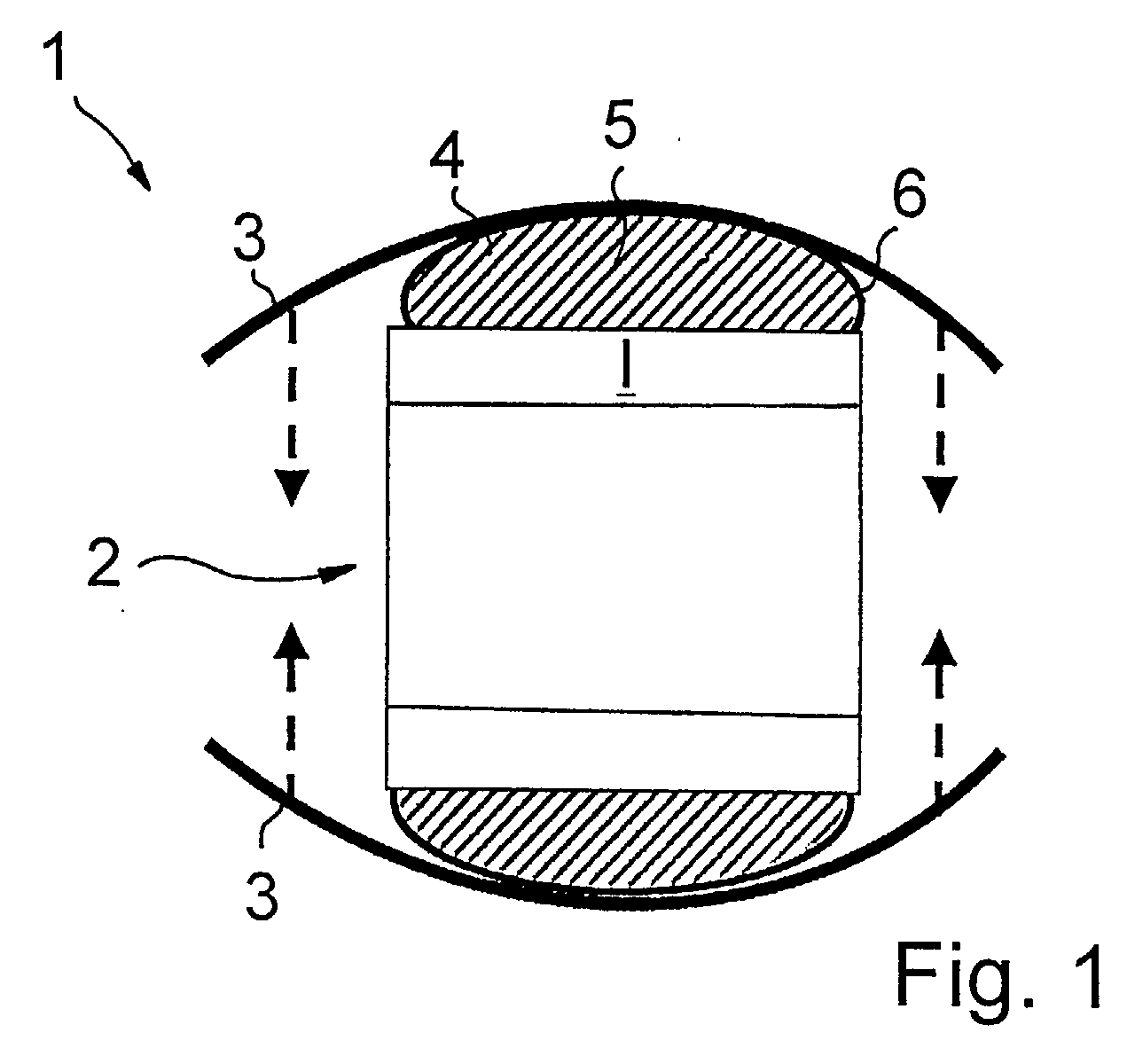
- FIG. 1 shows as a first exemplary embodiment a fuel cell stack 1 shown in a simplified manner, which has a stack structure 2 of planar single fuel cells not shown in detail and with an electrical insulation I and two end plates 3 integrated at the two ends of the stack structure 2.
- the end plates 3 are clamped together by means of indicated by arrows tie rods.
- the medium 4 is a Epoxy resin 5 with binder, which in a shell 6, in the present case in a Plastic bag, filled.
- the shell 6 with the still uncured epoxy resin 5 during assembly of the Fuel cell stack 1 inserted and braced by means of tie rods. Due to the liquid state of aggregation of the medium 4, this fits Medium 4 optimally to the surfaces of the individual components, i. the Stack structure 2 and the respective end plate 3 and produces a homogeneous Compression distribution over the entire contact surface to the Stack construction 2 and the end plate 3.
- Epoxy Resin 5 is a leak-proof and age-resistant medium 4, which is a very homogeneous compression of the stack structure 2 at low demands on the stiffness of the end plates 3 allows.
- a fuel cell stack 11 which is a stack structure 12 from not shown in detail planar single fuel cells and with an integrated at the ends of the stack structure 12, electrical insulation I and two end plates 13, with the aid of indicated by arrows Tie rod clamped.
- the end plates 13 from a as evenly distributed force acts on the stack structure 12 is on both sides between the stack structure 12 and the respective end plate 13 also provided a medium 14 for optimized pressure distribution.
- the medium 14 is tin 17.
- the liquid tin 17 is under pressure an opening 18 in the respective end plate 13 in the space between the Stack structure 12 and the end plate 13 filled.
- seals 19 are in the outer Area of the stack structure 12 is provided.
- the pressure will be up to Solidification of the tin 17 maintained. By the solidification is the Opening 18 closed by the tin 17 located therein.
- FIGS. 3 and 4 are provided in the same or equivalent parts with reference numerals higher by 20 compared to the first embodiment. Also in this embodiment, the deformations are exaggerated.
- a fuel cell stack 21 the one Stack structure 22 of not shown in detail planar single fuel cell and one at the ends of the stack structure 22 integrated, electrical insulation I and two end plates 23, with Help tightened by arrows indicated tie rods.
- the Medium already be preformed, so that the time and energy expenditure for the heat treatment and the medium is not reduced necessarily completely must take a plastic state.
- a fuel cell stack 31 the one Stack structure 32 of not shown in detail planar single fuel cell and one at the ends of the stack structure 32 integrated electrical insulation and two end plates 33, with the help clamped by indicated by arrows tie rods.
- the medium 34 itself off a material suitable as an insulator, so that no additional insulation is required.
- a fuel cell stack 41 which is a stack structure 42 from not shown in detail planar single fuel cells and with a built-in at the ends of the stack structure 42 electrical insulation I and two end plates 43, indicated by arrows Tie rod clamped.
- Stack structure 42 takes over, in contrast to the previous embodiments, in the contact area for Stack structure 42 during the bracing process locally into one plastic state transferred end plates 43 the function of Pressure distribution, so that the end plates 43 serve as a medium 44. there are the end plates 43 during assembly in a stack structure 42nd facing area plastically deformable.
- the material of the end plates is chosen so that the Endplates take on the function of electrical insulation and on a additional insulation can be dispensed with.
Landscapes
- Life Sciences & Earth Sciences (AREA)
- Engineering & Computer Science (AREA)
- Manufacturing & Machinery (AREA)
- Sustainable Development (AREA)
- Sustainable Energy (AREA)
- Chemical & Material Sciences (AREA)
- Chemical Kinetics & Catalysis (AREA)
- Electrochemistry (AREA)
- General Chemical & Material Sciences (AREA)
- Fuel Cell (AREA)
Abstract
Description
- Fig. 1
- eine schematische Ansicht eines Brennstoffzellenstapels gemäß dem ersten Ausführungsbeispiel,
- Fig. 2
- eine schematische Ansicht eines Brennstoffzellenstapels gemäß dem zweiten Ausführungsbeispiel,
- Fig. 3
- eine schematische Ansicht eines Brennstoffzellenstapels gemäß dem dritten Ausführungsbeispiel vor der Wärmebehandlung,
- Fig. 4
- eine schematische Ansicht des Brennstoffzellenstapels gemäß dem dritten Ausführungsbeispiel nach der Wärmebehandlung,
- Fig. 5
- eine schematische Ansicht eines Brennstoffzellenstapels gemäß dem vierten Ausführungsbeispiel vor der Wärmebehandlung,
- Fig. 6
- eine schematische Ansicht des Brennstoffzellenstapels gemäß dem vierten Ausführungsbeispiel nach der Wärmebehandlung,
- Fig. 7
- eine schematische Ansicht eines Brennstoffzellenstapels gemäß dem fünften Ausführungsbeispiel vor der Wärmebehandlung und
- Fig. 8
- eine schematische Ansicht des Brennstoffzellenstapels gemäß dem fünften Ausführungsbeispiel nach der Wärmebehandlung.
Claims (16)
- Brennstoffzellenstapel, welcher eine erste und eine zweite Endplatte (3;13; 23; 33; 43) sowie dazwischen angeordnete, planaren Brennstoffzellen aufweist, sowie eine Spannvorrichtung zum Verspannen der Brennstoffzellen zwischen den Endplatten (3; 13; 23; 33; 43), wobei im Brennstoffzellenstapel (1; 11; 21; 31; 41) ein Medium (4; 14; 24; 34; 44) zur Druckverteilung angeordnet ist, dadurch gekennzeichnet, dass das Medium (4; 14; 24; 34; 44) temporär plastisch verformbar ist.
- Brennstoffzellenstapel nach Anspruch 1, dadurch gekennzeichnet, dass das Medium (4; 14; 24; 34) zwischen der ersten Endplatte (3; 13; 23; 33) und der hierzu nächstliegenden Brennstoffzelle und/oder zwischen der zweiten Endplatte (3; 13; 23; 33) und der hierzu nächstliegenden Brennstoffzelle angeordnet und/oder dass das Medium (44) ein Teil der entsprechenden Endplatte (43) ist.
- Brennstoffzellenstapel nach einem der vorstehenden Ansprüche, dadurch gekennzeichnet, dass das Medium (4; 14; 24; 34; 44) ein zumindest teilweise oder vollständig ausgehärtetes oder erstarrtes Material ist.
- Brennstoffzellenstapel nach einem der vorstehenden Ansprüche, dadurch gekennzeichnet, dass das Medium (4; 14; 24; 34; 44) in einem für das Medium (4; 14; 24; 34; 44) im wesentlichen undurchlässigen Raum angeordnet ist.
- Brennstoffzellenstapel nach Anspruch 4, dadurch gekennzeichnet, dass der Raum durch eine Hülle (6), ein flexibles Behältnis oder durch die Endplatte (13), ein angrenzendes Element und mindestens ein Dichtmittel (19) begrenzt ist.
- Brennstoffzellenstapel nach einem der vorstehenden Ansprüche, dadurch gekennzeichnet, dass das Medium (4; 14; 24; 34; 44) ein Gießharz (5), Kunststoff oder Kunststoffgemisch, ein Metall (17) oder eine Metalllegierung ist.
- Brennstoffzellenstapel nach einem der vorstehenden Ansprüche, dadurch gekennzeichnet, dass das Medium (34) ein elektrischer Isolator (I) ist.
- Brennstoffzellenstapel nach einem der vorstehenden Ansprüche, dadurch gekennzeichnet, dass das Medium (4; 14; 24; 34; 44) temperaturbeständig bis 300°C ist.
- Brennstoffzellenstapel nach einem der vorstehenden Ansprüche, dadurch gekennzeichnet, dass das Medium (4; 14; 24; 34; 44) alterungs- und kriechbeständig ist.
- Brennstoffzellenstapel nach Anspruch 5, dadurch gekennzeichnet, dass die Hülle (6) oder das flexible Behältnis aus Kunststoff, einem organischen, natürlichen Material oder Metall ist.
- Zwischen- oder Endelement für einen Brennstoffzellenstapel (1; 11; 21; 31; 41) gemäß einem der vorstehenden Ansprüche mit einem Medium (4; 14; 24; 34; 44).
- Verfahren zum Zusammenbau eines Brennstoffzellenstapels (1; 11; 21; 31; 41), welcher eine erste und eine zweite Endplatte (3; 13; 23; 33; 43) sowie dazwischen angeordnete Brennstoffzellen aufweist, sowie eine Spannvorrichtung zum Verspannen der Brennstoffzellen, dadurch gekennzeichnet, dass zwischen der ersten Endplatte (3; 13; 23; 33) und der hierzu nächstliegenden Brennstoffzelle und/oder zwischen der zweiten Endplatte (3; 13; 23; 33) und der hierzu nächstliegenden Brennstoffzelle ein Medium (4; 14; 24; 34) angeordnet wird und/oder dass die erste Endplatte (43) und/oder die zweite Endplatte (43) einen Bereich mit einem Medium (44) aufweist, wobei das Medium (4; 14; 24; 34; 44) in plastischem Zustand eingebracht wird und/oder nach dem Einbringen temporär einen plastischen Zustand aufweist.
- Verfahren nach Anspruch 12, dadurch gekennzeichnet, dass das Medium (4; 14) bei einem Druck zwischen 0 und 100 bar eingebracht wird.
- Verfahren nach Anspruch 12 oder 13, dadurch gekennzeichnet, dass das Medium (4; 14; 44) zumindest teilweise ausgehärtet wird oder erstarrt.
- Verfahren nach Anspruch 13, dadurch gekennzeichnet, dass das Medium (4; 14; 24; 34; 44) temporär erhitzt wird.
- Verfahren nach einem der Ansprüche 12 bis 15, dadurch gekennzeichnet, dass das Medium (24; 34; 44) vorgeformt ist.
Applications Claiming Priority (2)
| Application Number | Priority Date | Filing Date | Title |
|---|---|---|---|
| DE10151452 | 2001-10-18 | ||
| DE10151452A DE10151452A1 (de) | 2001-10-18 | 2001-10-18 | Brennstoffzellenstapel |
Publications (2)
| Publication Number | Publication Date |
|---|---|
| EP1304757A2 true EP1304757A2 (de) | 2003-04-23 |
| EP1304757A3 EP1304757A3 (de) | 2006-11-29 |
Family
ID=7702927
Family Applications (1)
| Application Number | Title | Priority Date | Filing Date |
|---|---|---|---|
| EP02018751A Withdrawn EP1304757A3 (de) | 2001-10-18 | 2002-08-22 | Brennstoffzellenstapel |
Country Status (2)
| Country | Link |
|---|---|
| EP (1) | EP1304757A3 (de) |
| DE (1) | DE10151452A1 (de) |
Cited By (2)
| Publication number | Priority date | Publication date | Assignee | Title |
|---|---|---|---|---|
| WO2007001189A1 (en) * | 2005-06-29 | 2007-01-04 | Norsk Hydro Asa | An electrochemical cell stack |
| WO2014138856A1 (en) | 2013-03-12 | 2014-09-18 | Next Hydrogen Corporation | End pressure plate for electrolysers |
Families Citing this family (3)
| Publication number | Priority date | Publication date | Assignee | Title |
|---|---|---|---|---|
| DE102007011793A1 (de) * | 2007-03-12 | 2008-09-18 | Mtu Cfc Solutions Gmbh | Dichtungsvorrichtung für eine Brennstoffzellenanordnung |
| US9577284B2 (en) | 2010-02-26 | 2017-02-21 | GM Global Technology Operations LLC | Fuel cell stack enclosure |
| DE102012221407B4 (de) * | 2012-11-22 | 2024-10-10 | Ekpo Fuel Cell Technologies Gmbh | Endplattenanordnung für eine elektrochemische Vorrichtung |
Family Cites Families (11)
| Publication number | Priority date | Publication date | Assignee | Title |
|---|---|---|---|---|
| US4973531A (en) * | 1988-02-19 | 1990-11-27 | Ishikawajima-Harima Heavy Industries Co., Ltd. | Arrangement for tightening stack of fuel cell elements |
| JPH0754713B2 (ja) * | 1989-05-02 | 1995-06-07 | 株式会社日立製作所 | 燃料電池の締付装置、焼成装置及び焼成運転方法 |
| DE69015802T2 (de) * | 1990-03-01 | 1995-05-11 | Yoshitomi Onoda | Struktur zum Einbau einer Brennstoffzelle. |
| DE4309976A1 (de) * | 1993-03-26 | 1994-09-29 | Daimler Benz Ag | Elektrochemische Mehrzellenbatterie |
| US5547777A (en) * | 1994-02-23 | 1996-08-20 | Richards Engineering | Fuel cell having uniform compressive stress distribution over active area |
| JPH09259916A (ja) * | 1996-03-19 | 1997-10-03 | Mitsubishi Electric Corp | 燃料電池の締付装置 |
| AU8329398A (en) * | 1997-07-16 | 1999-02-10 | Ballard Power Systems Inc. | Resilient seal for membrane electrode assembly (mea) in an electrochemical fuel cell and method of making same |
| US6040072A (en) * | 1997-11-19 | 2000-03-21 | Lynntech, Inc. | Apparatus and method for compressing a stack of electrochemical cells |
| JP4031860B2 (ja) * | 1998-02-17 | 2008-01-09 | 本田技研工業株式会社 | 締め付け構造を有する燃料電池 |
| JP3388710B2 (ja) * | 1999-03-16 | 2003-03-24 | 三菱電機株式会社 | 燃料電池 |
| DE10003528C2 (de) * | 2000-01-27 | 2002-08-01 | Siemens Ag | Flexibles Zwischenelement und dessen Verwendung |
-
2001
- 2001-10-18 DE DE10151452A patent/DE10151452A1/de not_active Ceased
-
2002
- 2002-08-22 EP EP02018751A patent/EP1304757A3/de not_active Withdrawn
Cited By (3)
| Publication number | Priority date | Publication date | Assignee | Title |
|---|---|---|---|---|
| WO2007001189A1 (en) * | 2005-06-29 | 2007-01-04 | Norsk Hydro Asa | An electrochemical cell stack |
| WO2014138856A1 (en) | 2013-03-12 | 2014-09-18 | Next Hydrogen Corporation | End pressure plate for electrolysers |
| EP2971258A4 (de) * | 2013-03-12 | 2016-09-28 | Next Hydrogen Corp | Enddruckplatte für elektrolyseure |
Also Published As
| Publication number | Publication date |
|---|---|
| EP1304757A3 (de) | 2006-11-29 |
| DE10151452A1 (de) | 2003-04-30 |
Similar Documents
| Publication | Publication Date | Title |
|---|---|---|
| DE69315749T2 (de) | Brennstoffzellenstapel und Verfahren zu ihrer Zusammenpressung | |
| DE10207743A1 (de) | Elektrode für eine Polymerelektrolyt-Brennstoffzelle, Trennwand hierfür sowie Polymerelektrolyt-Brennstoffzelle und Elektrizitätserzeugungssystem unter Verwendung derselben | |
| DE2746172A1 (de) | Verbund von elektrochemischen festelektrolytzellen | |
| DE10225210A1 (de) | Dichtungsstruktur einer Brennstoffzelle | |
| EP1597786B1 (de) | Herstellung eines hochtemperatur-brennstoffzellenstapels | |
| DE102016004306A1 (de) | Brennstoffzellenstapel, Brennstoffzellensystem, Fahrzeug und Verfahren zum Fertigen eines Brennstoffzellenstapels | |
| DE102015225350A1 (de) | Gehäuse zur Aufnahme eines Brennstoffzellen-, Batterie- oder Kondensatorstapels | |
| DE102014210358A1 (de) | Brennstoffzellenstapel mit einer dummyzelle | |
| DE102022001673A1 (de) | Deckelbaugruppe für eine Batteriezelle und Batteriezelle | |
| EP3476000B1 (de) | Vorrichtung zur energieumwandlung, insbesondere brennstoffzelle oder elektrolyseur | |
| DE102021004963A1 (de) | Vorrichtung zur Verspannung eines Brennstoffzellenstapels oder Elektrolysezellenstapels | |
| DE102013020860A1 (de) | Zellblock für eine Batterie | |
| DE3520855C1 (de) | Galvanische Zelle mit Presskontaktierung | |
| DE112006000900T5 (de) | Brennstoffzelle, Verfahren und Vorrichtung zur Herstellung einer Brennstoffzelle | |
| EP1246283B1 (de) | Elektrisch isolierende Abstandshalter/Dichtungsanordnung | |
| EP1652260A2 (de) | Brennstoffzellenanordnung und vorrichtung zum befestigen einer brennstoffzellenanordnung an einem geh use | |
| DE102010011206A1 (de) | Brennstoffzellenstapel und Verfahren zu seiner Herstellung | |
| DE102017111514B4 (de) | Gehäuse für einen Stapel aus elektrochemischen Einheiten zur Montage in einer elektrochemischen Vorrichtung | |
| DE10151452A1 (de) | Brennstoffzellenstapel | |
| EP4427285A1 (de) | Elektrochemische zelle mit einer membran-elektroden-einheit, einer diffusionslage und einer verteilerplatte, und verfahren zum herstellen einer elektrochemischen zelle | |
| EP1338050B1 (de) | Brennstoffzellenmodul | |
| DE102018213155A1 (de) | Brennstoffzelle sowie Brennstoffzellenstapel | |
| DE60204908T2 (de) | Verfahren zur wiederverwendung von stromsammel-/verteilerplatten von polymermembran-brennstoffzellenstapeln | |
| WO2008119328A1 (de) | Interkonnektoranordnung und verfahren zur herstellung einer kontaktanordnung für einen brennstoffzellenstapel | |
| DE102020207919A1 (de) | Brennstoffzellenanordnung und Verfahren zur Herstellung einer Brennstoffzellenanordnung |
Legal Events
| Date | Code | Title | Description |
|---|---|---|---|
| PUAI | Public reference made under article 153(3) epc to a published international application that has entered the european phase |
Free format text: ORIGINAL CODE: 0009012 |
|
| AK | Designated contracting states |
Designated state(s): AT BE BG CH CY CZ DE DK EE ES FI FR GB GR IE IT LI LU MC NL PT SE SK TR |
|
| AX | Request for extension of the european patent |
Extension state: AL LT LV MK RO SI |
|
| RAP1 | Party data changed (applicant data changed or rights of an application transferred) |
Owner name: BEHR GMBH & CO. KG |
|
| PUAL | Search report despatched |
Free format text: ORIGINAL CODE: 0009013 |
|
| AK | Designated contracting states |
Kind code of ref document: A3 Designated state(s): AT BE BG CH CY CZ DE DK EE ES FI FR GB GR IE IT LI LU MC NL PT SE SK TR |
|
| AX | Request for extension of the european patent |
Extension state: AL LT LV MK RO SI |
|
| RIC1 | Information provided on ipc code assigned before grant |
Ipc: H01M 8/02 20060101ALI20061020BHEP Ipc: H01M 8/24 20060101AFI20030110BHEP |
|
| 17P | Request for examination filed |
Effective date: 20070529 |
|
| AKX | Designation fees paid |
Designated state(s): AT BE BG CH CY CZ DE DK EE ES FI FR GB GR IE IT LI LU MC NL PT SE SK TR |
|
| 17Q | First examination report despatched |
Effective date: 20071017 |
|
| GRAP | Despatch of communication of intention to grant a patent |
Free format text: ORIGINAL CODE: EPIDOSNIGR1 |
|
| STAA | Information on the status of an ep patent application or granted ep patent |
Free format text: STATUS: THE APPLICATION IS DEEMED TO BE WITHDRAWN |
|
| 18D | Application deemed to be withdrawn |
Effective date: 20110326 |