EP1304680A2 - Apparatus and method for synthesizing a plurality of waveforms in synchronized manner - Google Patents
Apparatus and method for synthesizing a plurality of waveforms in synchronized manner Download PDFInfo
- Publication number
- EP1304680A2 EP1304680A2 EP02019896A EP02019896A EP1304680A2 EP 1304680 A2 EP1304680 A2 EP 1304680A2 EP 02019896 A EP02019896 A EP 02019896A EP 02019896 A EP02019896 A EP 02019896A EP 1304680 A2 EP1304680 A2 EP 1304680A2
- Authority
- EP
- European Patent Office
- Prior art keywords
- waveform
- readout
- waveform data
- synchronizing
- blocks
- Prior art date
- Legal status (The legal status is an assumption and is not a legal conclusion. Google has not performed a legal analysis and makes no representation as to the accuracy of the status listed.)
- Withdrawn
Links
Images




Classifications
-
- G—PHYSICS
- G10—MUSICAL INSTRUMENTS; ACOUSTICS
- G10H—ELECTROPHONIC MUSICAL INSTRUMENTS; INSTRUMENTS IN WHICH THE TONES ARE GENERATED BY ELECTROMECHANICAL MEANS OR ELECTRONIC GENERATORS, OR IN WHICH THE TONES ARE SYNTHESISED FROM A DATA STORE
- G10H7/00—Instruments in which the tones are synthesised from a data store, e.g. computer organs
- G10H7/02—Instruments in which the tones are synthesised from a data store, e.g. computer organs in which amplitudes at successive sample points of a tone waveform are stored in one or more memories
-
- G—PHYSICS
- G10—MUSICAL INSTRUMENTS; ACOUSTICS
- G10H—ELECTROPHONIC MUSICAL INSTRUMENTS; INSTRUMENTS IN WHICH THE TONES ARE GENERATED BY ELECTROMECHANICAL MEANS OR ELECTRONIC GENERATORS, OR IN WHICH THE TONES ARE SYNTHESISED FROM A DATA STORE
- G10H1/00—Details of electrophonic musical instruments
- G10H1/02—Means for controlling the tone frequencies, e.g. attack or decay; Means for producing special musical effects, e.g. vibratos or glissandos
- G10H1/06—Circuits for establishing the harmonic content of tones, or other arrangements for changing the tone colour
- G10H1/08—Circuits for establishing the harmonic content of tones, or other arrangements for changing the tone colour by combining tones
-
- G—PHYSICS
- G10—MUSICAL INSTRUMENTS; ACOUSTICS
- G10H—ELECTROPHONIC MUSICAL INSTRUMENTS; INSTRUMENTS IN WHICH THE TONES ARE GENERATED BY ELECTROMECHANICAL MEANS OR ELECTRONIC GENERATORS, OR IN WHICH THE TONES ARE SYNTHESISED FROM A DATA STORE
- G10H7/00—Instruments in which the tones are synthesised from a data store, e.g. computer organs
- G10H7/008—Means for controlling the transition from one tone waveform to another
-
- G—PHYSICS
- G10—MUSICAL INSTRUMENTS; ACOUSTICS
- G10H—ELECTROPHONIC MUSICAL INSTRUMENTS; INSTRUMENTS IN WHICH THE TONES ARE GENERATED BY ELECTROMECHANICAL MEANS OR ELECTRONIC GENERATORS, OR IN WHICH THE TONES ARE SYNTHESISED FROM A DATA STORE
- G10H2240/00—Data organisation or data communication aspects, specifically adapted for electrophonic musical tools or instruments
- G10H2240/121—Musical libraries, i.e. musical databases indexed by musical parameters, wavetables, indexing schemes using musical parameters, musical rule bases or knowledge bases, e.g. for automatic composing methods
- G10H2240/145—Sound library, i.e. involving the specific use of a musical database as a sound bank or wavetable; indexing, interfacing, protocols or processing therefor
-
- G—PHYSICS
- G10—MUSICAL INSTRUMENTS; ACOUSTICS
- G10H—ELECTROPHONIC MUSICAL INSTRUMENTS; INSTRUMENTS IN WHICH THE TONES ARE GENERATED BY ELECTROMECHANICAL MEANS OR ELECTRONIC GENERATORS, OR IN WHICH THE TONES ARE SYNTHESISED FROM A DATA STORE
- G10H2240/00—Data organisation or data communication aspects, specifically adapted for electrophonic musical tools or instruments
- G10H2240/325—Synchronizing two or more audio tracks or files according to musical features or musical timings
-
- G—PHYSICS
- G10—MUSICAL INSTRUMENTS; ACOUSTICS
- G10H—ELECTROPHONIC MUSICAL INSTRUMENTS; INSTRUMENTS IN WHICH THE TONES ARE GENERATED BY ELECTROMECHANICAL MEANS OR ELECTRONIC GENERATORS, OR IN WHICH THE TONES ARE SYNTHESISED FROM A DATA STORE
- G10H2250/00—Aspects of algorithms or signal processing methods without intrinsic musical character, yet specifically adapted for or used in electrophonic musical processing
- G10H2250/025—Envelope processing of music signals in, e.g. time domain, transform domain or cepstrum domain
- G10H2250/035—Crossfade, i.e. time domain amplitude envelope control of the transition between musical sounds or melodies, obtained for musical purposes, e.g. for ADSR tone generation, articulations, medley, remix
-
- G—PHYSICS
- G10—MUSICAL INSTRUMENTS; ACOUSTICS
- G10H—ELECTROPHONIC MUSICAL INSTRUMENTS; INSTRUMENTS IN WHICH THE TONES ARE GENERATED BY ELECTROMECHANICAL MEANS OR ELECTRONIC GENERATORS, OR IN WHICH THE TONES ARE SYNTHESISED FROM A DATA STORE
- G10H2250/00—Aspects of algorithms or signal processing methods without intrinsic musical character, yet specifically adapted for or used in electrophonic musical processing
- G10H2250/541—Details of musical waveform synthesis, i.e. audio waveshape processing from individual wavetable samples, independently of their origin or of the sound they represent
- G10H2250/571—Waveform compression, adapted for music synthesisers, sound banks or wavetables
Definitions
- the present invention relates generally to apparatus and methods for producing waveforms of musical tones, voices or other desired sounds on the basis of waveform data read out from a waveform memory or the like, and more particularly to an improved waveform producing apparatus and method capable of producing waveforms that faithfully represent tone color variations effected by a human player using various styles of rendition or various kinds of articulation unique to a particular natural musical instrument.
- the basic principles of the present invention can be applied extensively to various types of equipment, apparatus and methods having the function of generating musical tones, voices or any other desired sounds, such as automatic performance devices, computers, electronic game devices and multimedia-related devices, not to mention electronic musical instruments.
- tone waveform used in this specification are not necessarily limited to a waveform of a musical tone alone and are used in a much broader sense that may embrace a waveform of a voice or any other desired type of sound.
- waveform memory readout The so-called "waveform memory readout” technique has already been well known and popularly used in the art, which prestores waveform data coded with a desired coding scheme, such as the PCM (Pulse Code Modulation), DPCM (Differential Pulse Code Modulation) or ADPCM (Adaptive Differential Pulse Code Modulation), and then reads out the thus-prestored waveform data at a rate corresponding to a desired tone pitch to thereby produce a tone waveform.
- PCM Pulse Code Modulation
- DPCM Dynamic Pulse Code Modulation
- ADPCM Adaptive Differential Pulse Code Modulation
- the waveform memory readout technique there has been known a scheme of prestoring waveform data of a complete waveform of a tone covering from the start to end thereof.
- the terms "loop waveform” are used to refer to a waveform to be read out repeatedly, i.e., in a "looped" fashion.
- the conventionally-known waveform memory readout technique performs pitch shift control of the waveform data of the harmonic component alone and does not performs the pitch shift control of the waveform data of the nonharmonic component.
- the pitch shift control thus performed only on the harmonic component's waveform data, waveform synthesis is likely to be performed with phase differences caused between the harmonic and nonharmonic components' waveform data.
- the conventionally-known waveform memory readout technique is not arranged to synthesize or combine together waveforms while synthesizing the respective phases of the harmonic and nonharmonic components' waveform data.
- the waveform tends to be produced with tone color deterioration, undesired noise, etc., and thus the conventional technique can not produce high-quality waveforms, corresponding to various styles of rendition (various kinds of articulation), in such a manner that the produced waveforms will be reproduced with good reproducibility.
- the conventionally-known waveform memory readout technique interconnects the waveform blocks by cross-fade synthesis between respective loop waveform segments of the blocks.
- the respective loop waveform segments of the waveform blocks are in phase with each other, they would undesirably cancel each other so that the cross-fade synthesis between the loop waveform segments can not be performed appropriately.
- the readout start timing of the harmonic component in the waveform blocks would be changed (delayed) by an amount corresponding to one cycle of the loop waveforms at the maximum, while the readout start timing of the corresponding nonharmonic component in the waveform blocks is left unchanged because no cross-fade synthesis is performed on the nonharmonic component.
- the readout start timing of the harmonic and nonharmonic components in the waveform blocks does not appropriately coincide with each other, which results in a difference in synthesis timing between the harmonic component's waveform data and the nonharmonic component's waveform data.
- a waveform producing apparatus which comprises: a storage section storing a plurality of sets of waveform data to be read out along a time axis, the storage section also storing, for each of the sets of waveform data, synchronizing information representative of a plurality of cycle synchronizing points that are indicative of periodic specific phase positions where the set of waveform data in question should be synchronized in phase with another of the sets of waveform data; a readout section for reading out at least two of the sets of waveform data from the storage section, the readout section also reading out, from the storage section, the synchronizing information stored for each of the at least two sets; and a control section for controlling readout, by the readout section, of at least one of the at least two sets of waveform data on the basis of the synchronizing information read out by the readout section in such a manner that respective readout locations of the at least two sets of waveform data are synchronized with each other at least at the specific phase position indicated by the cycle synchronizing point
- the waveform producing apparatus reads out the at least two sets of waveform data from the storage section while synchronizing the at least two sets at each of the specific phase positions preset as the cycle synchronizing points.
- the inventive waveform producing apparatus readily achieves phase synchronization between the sets of waveform data, so that it can easily produce high-quality waveforms, having sets of waveform data appropriately synchronized in phase, in correspondence with various styles of rendition (or various kinds of articulation).
- a waveform producing apparatus which comprises: a storage section storing a plurality of blocks of waveform data to be read out along a time axis, the storage section also storing, for each one of the blocks of waveform data, at least one piece of synchronizing position information indicative of a specific position where the one block should be synchronized with another of the blocks; a readout section for reading out at least two of the blocks of waveform data from the storage section in a parallel fashion, the readout section also reading out, from the storage section, the synchronizing position information stored for each of the at least two blocks; and a control section for controlling readout, by the readout section, of at least one of the at least two blocks of waveform data on the basis of the synchronizing position information read out by the readout section in such a manner that respective readout locations of the at least two blocks of waveform data to be read out in parallel are synchronized with each other at least at the specific position indicated by the read-out synchronizing position information.
- the waveform producing apparatus controls the readout, by the readout section, of at least one of the at least two blocks of waveform data in such a manner that the at least two blocks of waveform data are synchronized with each other at least at the specific position indicated by the read-out synchronizing position information.
- the inventive waveform producing apparatus readily achieves phase synchronization between the blocks of waveform data, and it can produce high-quality waveforms having blocks of waveform data appropriately synchronized in phase.
- a waveform producing apparatus which comprises: a storage section storing a plurality of blocks of waveform data, to be read out along a time axis, for each of a harmonic component composed of a periodic waveform component and a nonharmonic component composed of a nonperiodic waveform component, the storage section also storing, for each of the blocks, at least one piece of synchronizing position information indicative of a specific position where respective blocks of the harmonic component and nonharmonic component corresponding to the harmonic component should be synchronized with each other; a readout section for reading out respective blocks of the harmonic component and corresponding nonharmonic component in a parallel fashion; and a control section for controlling readout, by the readout section, of the block of waveform data of the nonharmonic component, on the basis of the synchronizing position information for the block of the harmonic component read out by the readout section, in such a manner that a readout location of the block of the nonharmonic component to be read out in parallel to the block of the harmonic
- the waveform producing apparatus of the invention can produce tone waveforms etc., presenting style-of-rendition-related characteristics of various performance tones, so that the produced tone waveforms will be reproduced with good reproducibility.
- the present invention may be constructed and implemented not only as the apparatus invention as discussed above but also as a method invention. Also, the present invention may be arranged and implemented as a software program for execution by a processor such as a computer or DSP, as well as a storage medium storing such a program. Further, the processor used in the present invention may comprise a dedicated processor with dedicated logic built in hardware, not to mention a computer or other general-purpose type processor capable of running a desired software program.
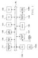
- Fig. 1 is a block diagram showing an exemplary hardware organization of a waveform producing apparatus in accordance with an embodiment of the present invention.
- the waveform producing apparatus illustrated here is constructed using a computer, and a predetermined waveform producing process is carried out by the computer executing predetermined waveform producing programs (software).
- the waveform producing process may be implemented by microprograms for execution by a DSP (Digital Signal Processor), rather than by such computer software.
- the waveform producing process of the present invention may be implemented by a dedicated hardware apparatus that includes discrete circuits or integrated or large-scale integrated circuit built therein.
- the waveform producing apparatus of the present invention may be implemented as an electronic musical instrument, karaoke device, electronic game device or other type of multimedia-related device, personal computer or any other desired form of product.
- the waveform producing apparatus of the invention may include other hardware components than the above-mentioned, it will be described hereinbelow as using only minimum necessary resources.
- the waveform producing apparatus in accordance with the embodiment of the present invention includes a CPU (Central Processing Unit) 101 functioning as a main control section of the computer.
- a bus e.g., data and address bus
- ROM Read-Only Memory
- RAM Random Access Memory
- switch panel 104 a panel display unit 105, a drive 106, a waveform input section 107, a waveform output section 108, a hard disk 109 and a communication interface 111.
- the CPU 101 carries out various processes directed to "waveform database creation” (to be later described in relation to Fig. 2), "waveform production” (to be later described in relation to Figs.
- programs 4 and 5 on the basis of predetermined software programs.
- These programs are supplied, for example, from a network via the communication interface 111 or from an external storage medium 106A, such as a CD or MO (Magneto-Optical disk) installed in the drive 106, and then stored in the hard disk 109.
- the desired program In execution of a desired one of the programs, the desired program is loaded from the hard disk 109 into the RAM 103; in an alternative, the programs may be prestored in the ROM 102.
- the ROM 102 stores therein various programs and data to be executed or referred to by the CPU 101.
- the RAM 103 is used as a working memory for temporarily storing various performance-related information and various data generated as the CPU 101 executes the programs, or as a memory for storing a currently-executed program and data related to the currently-executed program. Predetermined address regions of the RAM 103 are allocated to various functions and used as various registers, flags, tables, memories, etc.
- the switch panel 104 includes various operators for instructing tone sampling, editing the sampled waveform data, entering various pieces of information, etc.
- the switch panel 104 may be, for example, in the form of a ten-button keypad for inputting numerical value data, keyboard for inputting character/letter data, or panel switches.
- the switch panel 104 may also include other operators for selecting, setting and controlling a pitch, color, effect, etc. of each tone to be generated.
- the panel display unit 105 displays various information input via the switch panel 104, the sampled waveform data, etc. and comprises, for example, a liquid crystal display (LCD), CRT (Cathode Ray Tube) and/or the like.
- the waveform input section 107 contains an A/D converter for converting an analog input tone signal, introduced via an external waveform input device such as a microphone, into digital data (waveform data sampling), and inputs the thus-sampled digital waveform data into the RAM 103 or hard disk 109 as original waveform data from which to produce desired waveform data to be used for production of a desired waveform.
- the thus-input original waveform data are divided into waveform data of harmonic and nonharmonic components, and the thus-divided harmonic and nonharmonic components' waveform data are stored in a waveform database.
- waveform data of each tone signal corresponding to performance information are produced using the harmonic component's waveform data and nonharmonic component's waveform data selectively read out from the waveform database.
- waveform database above-mentioned waveform database.
- a plurality of tone signals can be generated simultaneously.
- the thus-produced waveform data of each tone signal are given via the bus BL to the waveform output section 108 and then stored in a buffer thereof.
- the waveform output section 108 reads out the buffered waveform data at a predetermined output sampling frequency and then sends the thus read-out waveform data to a sound system 108A after D/A-converting the waveform data.
- each tone signal output from the waveform output section 108 is sounded or audibly reproduced via the sound system 108A.
- the hard disk 109 is provided to store various data to be used for synthesizing waveforms corresponding to various waveform data and styles of rendition, a plurality of kinds of performance-related data such as tone color data composed of various tone color parameters, and data related to control of various programs to be executed by the CPU 101 and the like.
- the drive 106 functions to drive a removable disk (external storage medium 106A) that stores thereon various data to be used for synthesizing waveforms corresponding to various waveform data and styles of rendition, a plurality of kinds of performance-related data, such as tone color data composed of various tone color parameters and data related, for example, to control of various programs to be executed by the CPU 101, and/or the like.
- the external storage medium 106A to be driven by the drive 106 may be any one of various known removable-type media, such as a floppy disk (FD), compact disk (CD-ROM or CD-RW), magneto-optical (MO) disk, digital versatile disk (DVD). or semiconductor memory.
- Particular stored contents (control program) of the external storage medium 106A set in the drive 106 may be loaded directly into the RAM 103, without being first loaded into the hard disk 109. Note that the approach of supplying a desired program via the external storage medium 106A or via a communication network is very advantageous in that it can greatly facilitate version upgrade of the control program, addition of a new control program, etc.
- the communication interface 111 is connected to a communication network, such as a LAN (Local Area Network), the Internet or telephone line network, via which it may be connected to a desired sever computer or the like (not shown) so as to input a control program, waveform data, performance information or the like to the waveform producing apparatus of the invention.
- a communication network such as a LAN (Local Area Network), the Internet or telephone line network
- a desired sever computer or the like not shown
- the control program, waveform data or the like can be downloaded from the server computer via the communication interface 111 to the waveform producing apparatus of the invention.
- the waveform producing apparatus of the invention which is a "client" sends a command to request the server computer to download the control program, waveform data or the like by way of the communication interface 111 and communication network.
- the server computer delivers the requested control program, waveform data or the like to the waveform producing apparatus via the communication network.
- the waveform producing apparatus of the invention receives the control program, waveform data or the like from the server computer via the communication network and communication interface 111 and cumulatively stores the received control program, waveform data or the like into the hard disk 109. In this way, the necessary downloading of the control program, waveform data or the like is completed.
- the waveform producing apparatus of the invention may further include a MIDI interface so as to receive MIDI performance information.
- a music-performing keyboard and performance operating equipment may be connected to the bus BL so that performance information can be supplied to the waveform producing apparatus by an actual real-time performance.
- an external storage medium 106A containing performance information of a desired music piece may be used to supply the performance information of the desired music piece to the waveform producing apparatus.
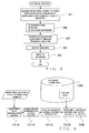
- FIG. 2 is a flow chart showing an exemplary operational sequence of the waveform database creation process carried out in the above-described waveform producing apparatus of the invention, which is directed to creating waveform data (i.e., vector data) on the basis of waveforms of tones actually performed with various styles of rendition (or various kinds of articulation) in such a manner that the created waveform data correspond to the various styles of rendition (kinds of articulation).
- waveform data i.e., vector data
- step S1 waveforms are acquired which correspond to tones actually performed on various natural musical instruments with various styles of rendition.
- waveform data of various tones actually performed on various natural musical instruments are acquired via an external waveform input device, such as a microphone, through the waveform input section 107, and the waveform data of these performance tones (i.e., original waveforms) are stored in predetermined areas of the hard disk 109.
- the thus-acquired original waveforms of each of the performance tones corresponding to the various performance styles unique to the natural musical instruments are segmented every characteristic portion, then subjected to a tuning operation and then given file names.
- the acquired original waveform of each of the performance tones is first segmented into partial waveforms (waveform segmentation), each representing a characteristic waveform variation, such as waveforms of nonsteady state portions like an attack-portion waveform, release-portion waveform and joint-portion and waveforms of steady state portions like a body-portion waveform.
- waveform segmentation a characteristic waveform variation
- the pitch of each of the individual segmented partial waveforms, covering one or two or more wave cycles of the tone in question is identified and modified as necessary (tuning).
- unique file names are imparted to the segmented waveforms (file name impartment).
- the partial waveforms having been processed at step S2 are divided into waveform components through predetermined frequency analysis.
- each of the segmented partial waveforms is subjected to Fast Fourier Transform (FFT) for division into harmonic and nonharmonic components.
- FFT Fast Fourier Transform
- characteristics of various waveform factors such as a pitch and amplitude, are extracted from each of the harmonic and nonharmonic components; here, extraction is made of a "waveform shape" (Timbre) factor representing only extracted characteristics of a waveform shape normalized in pitch and amplitude, a "pitch” factor representing extracted characteristics of a pitch variation from a predetermined reference pitch, and an "amplitude” factor representing extracted characteristics of an amplitude envelope.
- Timbre waveform shape
- Pitch pitch variation
- amplitude representing extracted characteristics of an amplitude envelope.
- no pitch factor is extracted because the nonharmonic component has no pitch variation characteristics.
- joint portion is a waveform portion interconnecting successive tones (or successive tone portions) with a desired style of rendition.
- waveform vector data are created. Namely, for each of the above-mentioned factors, such as the waveform (timbre), pitch and amplitude factors of the divided waveform components (e.g., harmonic and nonharmonic components), a plurality of sample values of successive sample points are extracted dispersedly or, if necessary, consecutively, and each extracted sample value group or train of the successive sample points thus obtained is given a different or unique vector ID (identification information) and stored in memory along with data indicative of a time position thereof.
- vector data such sample data are referred to as "vector data”.
- the instant embodiment creates respective vector data of the waveform (timbre) factor, pitch factor and amplitude factor of the harmonic component, and respective vector data of the waveform (timbre) factor and amplitude factor of the nonharmonic component.
- a suitable position is stored as a cycle synchronizing position or point CSP, for each wave cycle of the harmonic component's waveform extracted by the frequency analysis (see Fig. 3), with a view to synchronizing the harmonic component and nonharmonic component as will be later described in detail.
- the cycle synchronizing points CSP are synchronizing position information to be used for performing waveform synthesis by reading out the harmonic component's waveform vector data set and nonharmonic component's waveform vector data set in such a manner that respective readout locations of these harmonic and nonharmonic components' waveform vector data sets are synchronized on a periodic basis; specifically, predetermined addresses or the like are stored as such cycle synchronizing points CSP.
- the vector data sets of the various factors of the components, having been created in the above-described manner are cumulatively written into a waveform database provided in the hard disk 9 or the like.
- the instant embodiment instead of fully storing a complete waveform of each of tones performed on various natural musical instruments in various styles of rendition, extracts only partial waveforms (e.g., attack-portion waveform, body-portion waveform, release-portion waveform, joint-portion waveform, etc.) necessary for a waveform shape variation, and then stores the extracted partial waveforms in compressed form using a hierarchical compression scheme that compresses the partial waveforms for each of various hierarchical levels, such as the harmonic/nonharmonic component and factors.
- a hierarchical compression scheme that compresses the partial waveforms for each of various hierarchical levels, such as the harmonic/nonharmonic component and factors.
- Figs. 3A to 3D are conceptual diagrams showing examples of harmonic component's waveform vector data and nonharmonic component's waveform vector data created on the basis of a first embodiment of the synchronizing method. More specifically, Figs. 3A to 3D show examples of harmonic and nonharmonic components' waveform vector data sets of an attack, body, joint and release portions, respectively, using respective amplitude envelopes of the partial waveforms. Note however that loop waveform segments are shown only schematically in these figures. In each of Figs. 3A to 3D, the example of the harmonic component's waveform vector data (HW) are shown on an upper row while the example of the nonharmonic component's waveform vector data (NHW) are shown on a lower row.
- HW harmonic component's waveform vector data
- NHW nonharmonic component's waveform vector data
- the harmonic component's waveform vector data (HW) of the attack portion comprise a combination of a characteristic waveform block segment where data indicative of a characteristic waveform shape are stored in succession (hatched part in the figure) and a loop waveform segment that follows the characteristic waveform block segment and that can be read out repeatedly (filled-in-black part in the figure).
- the characteristic waveform block segment is a high-quality waveform segment (nonloop waveform segment) having characteristics of a style of rendition (or articulation) etc.
- the harmonic component's waveform vector data (HW) of the body portion comprise a repeated combination of data of one or a plurality of loop waveform segments. As shown in Fig.
- the harmonic component's waveform vector data (HW) of the joint portion comprise a combination of data of a loop waveform segment, a characteristic waveform block segment and a loop waveform segment.
- the harmonic component's waveform vector data (HW) of the release portion comprise a combination of data of loop waveform segments and a characteristic waveform block segment. Because such an attack portion, body portion, joint portion, release portion, etc. are connected together via the loop waveform segments, one loop waveform segment is positioned before and/or behind the characteristic waveform block segment of each of the attack portion, body portion, joint portion, release portion, etc.
- Each of the loop waveform segments is a unit waveform element of a relatively monotonous tone portion which consists of one or an appropriate plurality of wave cycles, and the attack, body, joint and release portions can be connected together through repeated readout of such loop waveform segments.
- the harmonic component's waveform vector data set of the attack portion, body portion, joint portion, release portion, etc. is stored using, as cycle synchronizing points or positions CSP, predetermined positions (denoted by double-head arrows and dotted lines in Figs. 3A to 3D) corresponding to the waveform cycles.
- the nonharmonic component's waveform vector data set (NHW) corresponding to the harmonic component's waveform vector data set (HW) is stored using, as its cycle synchronizing points CSP, predetermined positions (denoted by dotted lines in Figs. 3A to 3D) corresponding to the cycle synchronizing points CSP of the harmonic component's waveform vector data set.
- the double-head arrows denoted between the harmonic component's waveform vector data and the nonharmonic component's waveform vector data show, for convenience of illustration, the positions set as the corresponding cycle synchronizing points CSP of both of the harmonic and nonharmonic components' waveform vector data.
- the cycle synchronizing points CSP of the harmonic and nonharmonic components' waveform vector data are set at appropriate positions for each of the wave cycles of the harmonic component's waveform obtained through the frequency analysis (see step S3 of Fig. 2) (i.e., at desired phase-synchronizing positions, more specifically, at appropriate positions corresponding to time positions of the input waveform before undergoing the harmonic/ nonharmonic component division operation): hereinafter, these positions will be simply called “time positions").
- the harmonic and nonharmonic components' waveform vector data sets are to be synchronized with each other at appropriate positions for each of the waveform cycles, appropriate time positions within each of the waveform cycles are stored as the cycle synchronizing points CSP; alternatively, when the harmonic and nonharmonic components' waveform vector data sets are to be synchronized with each other at appropriate positions for every predetermined plurality of the waveform cycles, appropriate time positions within every such predetermined plurality of the waveform cycles are stored as the cycle synchronizing points CSP.
- the cycle sync point CSP may be set every n (which may be either an integer or decimal) multiple of one wave cycle of the harmonic component's waveform having been subjected to the frequency analysis, it is most preferable that the cycle synchronizing points CSP be set at appropriate positions for each wave cycle of the harmonic component's waveform. More specifically, the harmonic and nonharmonic components' waveform vector data are read out in accordance with predetermined readout addresses, and thus, in practice, the predetermined addresses are stored as the cycle sync points CSP. However, because the characteristic waveform block segment generally has no periodicity, the cycle synchronizing points CSP need not be set in such a characteristic waveform block segment for each wave cycle.
- Fig. 4 is a block diagram showing an example of the waveform production process performed by dedicated hardware in the waveform producing apparatus
- Fig. 5 is a conceptual diagram showing an exemplary detailed structure of a wave synthesis section 101D shown in Fig. 4.
- Music piece data reproduction section 101A reproduces music piece data imparted with data indicative of style-of-rendition symbols. Namely, first of all, the music piece data reproduction section 101A receives music piece data imparted with data indicative of style-of-rendition symbols (i.e., performance information). Ordinary musical scores have written thereon various musical signs, such as dynamic signs (e.g., crescendo and decrescendo), tempo signs (e.g., allegro and ritardando), slur sign, tenuto sign and accent signs, which can not be directly converted into MIDI data. Thus, the waveform producing apparatus of the invention converts these musical signs into style-of-rendition data.
- dynamic signs e.g., crescendo and decrescendo
- tempo signs e.g., allegro and ritardando
- slur sign tenuto sign and accent signs
- the music piece data reproduction section 101A receives such style-of-rendition-symbol-imparted music piece data.
- Music score interpretation section (player) 101B performs a musical score interpretation operation. Specifically, the musical score interpretation section (player) 101B creates predetermined style-of-rendition designating information on the basis of MIDI data and style-of-rendition symbols contained in the style-of-rendition-symbol-imparted music piece data, and then it outputs the thus-created style-of-rendition designating information to a style-of-rendition synthesis section (articulater) 101C along with corresponding time information.
- the style-of-rendition synthesis section (articulater) 101C creates packet streams corresponding to the style-of-rendition designating information created by the musical score interpretation section (player) 101B and vector parameters pertaining to the packet streams, and it supplies the thus-created packet streams and vector parameters to the waveform synthesis section 101D.
- Data sets supplied to the waveform synthesis section 101D as the packet streams each include a vector ID, time information, input note number, etc.
- the waveform synthesis section 101D retrieves, from the waveform database (hard disk) 109, vector data corresponding to the packet streams, modifies the vector data in accordance with the vector parameters, and synthesizes or combines together waveforms on the basis of the modified vector data to thereby produce a tone waveform.
- Waveform output section 108 outputs the tone waveform produced by the waveform synthesis section 101D in the above-mentioned manner.
- the style-of-rendition synthesis section (articulater) 101C supplies the created packet streams to packet queue buffers 21 to 25 provided in corresponding relation to the factors of the harmonic and nonharmonic components. Namely, the packet streams, created by the style-of-rendition synthesis section (articulater) 101C for the individual factors of the harmonic and nonharmonic components, are sequentially input to the predetermined packet queue buffers 21 to 25 on a packet-by-packet basis.
- the style-of-rendition synthesis section (articulater) 101C performs various management and control of the waveform synthesis section 101D, such as packet stream management related to creation/deletion of the individual vector data and connection between the vector data and reproduction control for creation of a desired waveform and reproduction/reproduction termination of the created desired waveform.
- the packets supplied from the style-of-rendition synthesis section (articulater) 101C are accumulated in the corresponding packet queue buffers 21 to 25, via which they are sequentially sent to a vector loader 20 in predetermined order. Then, the vector loader 20 refers to the respective vector IDs of the packets to thereby read out, from the waveform database 109, original vector data corresponding to the respective vector IDs of the packets.
- the vector data read out from the waveform database 109 are delivered to predetermined vector decoders 31 to 35 provided in corresponding relation to the factors of the components, and each of these vector decoders 31 to 35 produces a tone waveform of the corresponding factor.
- the vector decoders 31 to 35 each read out various data, such as the vector ID and time information, included in the corresponding packet and thereby produce a desired waveform in a time-serial fashion.
- the harmonic component's amplitude vector decoder 31 produces an envelope shape of the amplitude factor of the harmonic component
- the harmonic component's pitch vector decoder 32 produces an envelope shape of the pitch factor of the harmonic component
- the harmonic component's timbre vector decoder 33 produces a waveform of the timbre factor of the harmonic component.
- the nonharmonic component's amplitude vector decoder 34 produces an envelope shape of the amplitude factor of the nonharmonic component
- the nonharmonic component's timbre vector decoder 35 produces an envelope shape of the timbre factor of the nonharmonic component.
- the harmonic component's timbre vector decoder 33 produces a harmonic component's waveform having imparted thereto the envelope shape of the harmonic component's amplitude factor and envelope shape of the harmonic component's pitch factor produced by the harmonic component's amplitude vector decoder 31 and harmonic component's pitch vector decoder 32, respectively, and then the timbre vector decoder 33 outputs the thus-produced harmonic component's waveform to a mixer 38.
- the harmonic component's timbre vector decoder 33 receives the envelope shape of the harmonic component's amplitude factor as a vector control instruction (i.e., gain input) for gain control and the envelope shape of the harmonic component's pitch factor as another vector control instruction (i.e., readout speed input) for controlling readout locations of vector data corresponding to the input note number, and then, the harmonic component's timbre vector decoder 33 modifies the harmonic component's waveform vector data, read out from the waveform database 109, in accordance with these vector control instructions.
- a vector control instruction i.e., gain input
- the envelope shape of the harmonic component's pitch factor as another vector control instruction (i.e., readout speed input) for controlling readout locations of vector data corresponding to the input note number
- the harmonic component's timbre vector decoder 33 sends a predetermined signal --in this embodiment, cycle sync flag (CSF) signal--, to the nonharmonic component's timbre vector decoder 35.
- CSF cycle sync flag
- the nonharmonic component's timbre vector decoder 35 is supplied with no vector control instruction (i.e., speed input) for controlling readout locations of vector data corresponding to the input note (e.g., note number).
- the timbre vector decoder 35 when the nonharmonic component's timbre vector decoder 35 has received the predetermined signal (e.g., cycle sync flag (CSF) signal) transmitted from the harmonic component's timbre vector decoder 33 in response to one of the cycle synchronizing points CSP of the harmonic component's waveform vector data, the timbre vector decoder 35 jumps the readout location of the nonharmonic component's waveform vector data to a predetermined position (e.g., data address) previously set as the cycle synchronizing point CSP in the nonharmonic component's waveform vector data, so that the respective phases of the harmonic and nonharmonic components' waveforms are synchronized with each other. Such phase synchronization will be later described in greater detail.
- a predetermined position e.g., data address
- the nonharmonic component's timbre vector decoder 35 produces a nonharmonic component's waveform having imparted thereto the envelope shape of the harmonic component's amplitude factor produced by the nonharmonic component's amplitude vector decoder 34, and then the timbre vector decoder 35 outputs the thus-produced nonharmonic component's waveform to the mixer 38. More specifically, only the envelope shape of the nonharmonic component's amplitude factor is given to the nonharmonic component's timbre vector decoder 35 as the vector control instruction (i.e., gain input) for controlling the gain. In this way, the nonharmonic component's waveform vector data read out from the waveform database 109 are modified appropriately to produce a nonharmonic component's waveform.
- the vector control instruction i.e., gain input
- the thus-produced harmonic and nonharmonic components' waveforms are mixed together via the mixer 38 to thereby produce a tone waveform.
- the mixer 38 mixes together the harmonic component's waveform produced by the harmonic component's timbre vector decoder 33 and nonharmonic component's waveform produced by the nonharmonic component's timbre vector decoder 35, so as to produce an ultimate tone waveform.
- the harmonic component's timbre vector decoder 33 sends the predetermined signal (e.g., cycle sync flag (CSF) signal) to the corresponding nonharmonic component's timbre vector decoder 35, so that the nonharmonic component's timbre vector decoder 35 can then read out the nonharmonic component's waveform vector data while periodically synchronizing the phases of the harmonic component's waveform produced by the harmonic component's timbre vector decoder 33 and nonharmonic component's waveform produced by the nonharmonic component's timbre vector decoder 35.
- CSF cycle sync flag
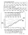
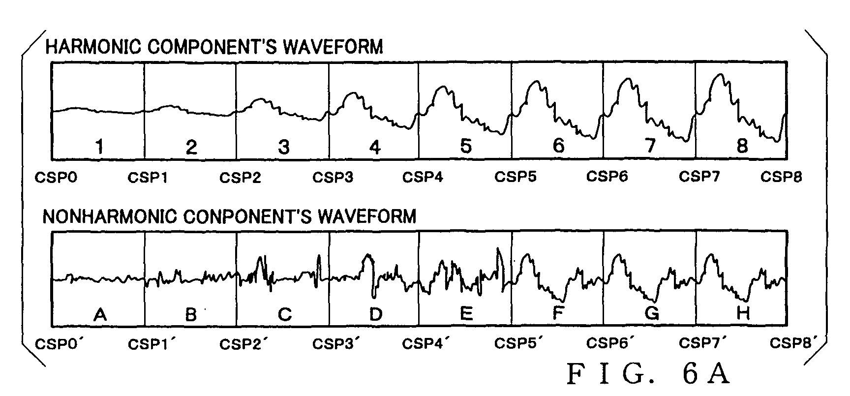
- Figs. 6A to 6C are conceptual diagrams explanatory of the periodic, synchronized readout of the harmonic and nonharmonic components' waveforms based on the cycle synchronizing points CSP. More specifically, Fig.
- FIG. 6A is a waveform diagram schematically showing harmonic component's waveform vector data read out from the waveform database (hereinafter referred to as a "harmonic component's original waveform") and corresponding nonharmonic component's waveform vector data read out from the waveform database (hereinafter referred to as a "nonharmonic component's original waveform").
- Fig. 6B is a conceptual diagram explanatory of progression in addresses to be used for reading out the nonharmonic component's original waveform in a case where the harmonic component's original waveform has been read out in accordance with a predetermined pitch (raised pitch in this case). Further, Fig.
- FIG. 6C is a waveform diagram schematically showing the nonharmonic component's waveform having been read out in accordance with the address progression of Fig. 6B (i.e., results of the periodic, synchronized readout of the nonharmonic component's waveform using the cycle synchronizing points CSP. Note however that the description will be made about the periodic, synchronized readout of only given portions of the harmonic and nonharmonic components' waveforms.
- cycle synchronizing point CSP0 corresponding to a not-shown section (waveform section 0) of the harmonic waveform
- cycle synchronizing point CSP0' set in the nonharmonic component's waveform in corresponding relation to the cycle synchronizing point CSP0 of the harmonic waveform.
- the harmonic component's original waveform contains the cycle synchronizing point CSP at a predetermined position for every predetermined number of wave cycle units (e.g., for each wave cycle unit).
- the harmonic component's original waveform contains eight cycle synchronizing points CSP1 to CSP8 corresponding to eight waveform sections 1 to 8 divided from each other every predetermined wave cycle unit.
- the nonharmonic component's original waveform, corresponding to the harmonic component's original waveform contains eight cycle synchronizing points CSP1' to CSP8' that correspond in position to the eight cycle synchronizing points CSP1 to CSP8 corresponding to eight waveform sections 1 to 8 of the harmonic component's original waveform.
- waveform sections 1 to 8 obtained by dividing the harmonic component's original waveform at the eight cycle synchronizing points CSP1 to CSP8 and waveform sections A to H obtained by dividing the nonharmonic component's original waveform at the eight cycle synchronizing points CSP1' to CSP8' are divided at same wave cycle units.
- the harmonic component's original waveform and the nonharmonic component's original waveform are synchronized in phase with each other.
- the waveform diagram shown in the top row of Fig. 6B represents the harmonic component's original waveform of Fig. 6A read out by the harmonic component's timbre vector decoder 33 in accordance with a predetermined pitch.
- the thus read-out harmonic component's original waveform is denoted as time-axially contracted as compared to the one of Fig, 6A, which means that the harmonic component's original waveform of Fig. 6A has been read out in a raised pitch.
- the timbre vector decoder 33 sends the above-mentioned CSF signal to the corresponding nonharmonic component's timbre vector decoder 35 (see Fig. 4 above).
- the harmonic component's timbre vector decoder 33 sends a series of the CSF signals to the nonharmonic component's timbre vector decoder 35 in the following manner: at time point t1, CSF signal CSF(1) corresponding to the cycle synchronizing point CSP1; at time point t2, CSF signal CSF(2) corresponding to the cycle synchronizing point CSP2; at time point t3, CSF signal CSF(3) corresponding to the cycle synchronizing point CSP3; at time point t4, CSF signal CSF(4) corresponding to the cycle synchronizing point CSP4; at time point t5, CSF signal CSF(5) corresponding to the cycle synchronizing point CSP5; at time point t6, CSF signal CSF(6) corresponding to the cycle synchronizing point CSP6; at time point t7, CSF signal CSF(7) corresponding to the cycle synchronizing point CSP7; at time point t8, CSF signal CSF(8) corresponding to the cycle synchronizing point CSP8; and at time point point t1, C
- a variation over time in waveform readout locations i.e. address progression
- an actual address progression is denoted by solid lines
- a virtual address progression is denoted by broken lines.
- the actual address progression represents a variation over time in actual readout locations (readout address locations) to be used by the nonharmonic component's timbre vector decoder 35 to read out the nonharmonic component's waveform
- the virtual address progression represents a variation over time in virtual readout locations (virtual readout address locations).
- the nonharmonic component's timbre vector decoder 35 shifts the current actual readout location of the nonharmonic component's original waveform to the cycle synchronizing point CSP immediately before the corresponding virtual readout location.
- virtual readout location is used herein to refer to a readout location that would be used if the waveform readout operation is continued virtually without being influenced by the readout of the cycle synchronizing point CSP.
- the speed of the virtual address progression in the illustrated example is identical to the readout speed (i.e., actual address progression speed) of the nonharmonic component's original waveform.
- the broken lines representing the virtual address progression have a same inclination angle as the solid lines representing the actual address progression.
- the readout of the nonharmonic component's original waveform is initiated at time point t0.
- the CSF signal CSF(1) is received in accordance with the cycle synchronizing point CSP1 set in the harmonic component's waveform. Because the address location immediately before the virtual address location, based on the virtual address progression, at this time point t1 is "CSP0"', the actual address is jumped back to the address location CSP0', so that the readout of the nonharmonic component's waveform is re-started at the address location CSP0'.
- waveform section A of the nonharmonic component's waveform in a time period from time point t0 to time point t1 as shown in Fig. 6C, waveform section A is again read out from the beginning at time point t1.
- the CSF signal CSF(2) is received in accordance with the cycle synchronizing point CSP2 set in the harmonic component's waveform.
- the address location immediately before the virtual address location, based on the virtual address progression, at this time point t2 is "CSP1"'
- the actual address is jumped back to the address location CSP1', so that the readout of the nonharmonic component's waveform is carried out from the address location CSP1' onward.
- the readout of waveform section A initiated at time point t1 is halted on the way, and then the readout of waveform section B is initiated.
- the CSF signal CSF(3) is received in accordance with the cycle synchronizing point CSP3 set in the harmonic component's waveform.
- the address location immediately before the virtual address location, based on the virtual address progression, at this time point t3 is "CSP1"'
- the actual address is jumped back to the address location CSP1', so that the readout of waveform section B is re-started at the address location CSP1'.
- the CSF signal CSF(4) is received in accordance with the cycle synchronizing point CSP4 set in the harmonic component's waveform. Because the address location immediately before the virtual address location, based on the virtual address progression, at this time point t4 is "CSP2"', the actual address is jumped back to the address location CSP2', so that the readout of waveform section C is initiated at the address location CSP2'.
- waveform section B is repetitively read out from the beginning to an enroute point thereof.
- the CSF signals are received sequentially in accordance with the subsequent cycle synchronizing points CSP5 to CSP8 (CSP9) so that the readout of the nonharmonic component's waveform is continued with the actual address location varied at each individual time point when the CSF signal is received from the harmonic component's timbre vector decoder 33.
- the nonharmonic component's timbre vector decoder 35 can read out the nonharmonic component's waveform in accordance with the actual address progression of Fig. 6B so that the read-out waveform assumes a shape as illustratively shown in Fig. 6C.
- the harmonic component's waveform shown in Fig. 6B and the nonharmonic component's waveform shown in Fig. 6C are read out in such a manner that the two waveforms are synchronized with each other every predetermined cycle, i.e. at each predetermined position where the cycle synchronizing point CSP is set.
- the instant embodiment allows the harmonic component's waveform and nonharmonic component's waveform to be synchronized in phase with each other. Therefore, when the harmonic component's waveform and nonharmonic component's waveform are being synthesized or combined together, these two waveforms can be made to have no phase difference at each of the predetermined periodic positions. In this manner, the instant embodiment of the waveform producing apparatus can synthesize together the harmonic and nonharmonic components' waveforms while periodically synchronizing the respective phases.
- the waveform producing apparatus of the invention arranged in the above-described manner can produce a high-quality waveform free of tone quality deterioration, noise, etc., by eliminating the phase differences at the peaks or the like in the spike-shaped waveform parts.
- the speed of the virtual address progression used in the readout of the nonharmonic component's waveform shown in Fig. 6B may be raised or lowered, in stead of the progression speed corresponding to the pitch of the nonharmonic component's original waveform being used just as it is.
- the speed of the virtual address progression used in the readout of the nonharmonic component's waveform may be raised or lowered in correspondence with the pitch of the harmonic component's waveform.
- the periodic phase synchronization of the harmonic and nonharmonic components' waveforms may be performed using a simplified algorithm such that, upon generation of the CSF signal, the readout address is jumped to a nearest cycle synchronizing point, instead of using the above-mentioned virtual addresses.
- the above-described inventive control for periodically synchronizing the readout locations of the harmonic and nonharmonic components' waveforms in accordance with the cycle synchronizing points CSP may be applied to other cases than the above-described case where the readout speeds of the individual vector data vary in response to a tone pitch.
- the above-described readout location synchronization control may be applied to a case where time-axial stretch/contraction of an entire waveform to be produced is controlled by performing TSC control on an attack portion and joint portion, or an attack portion and release portion, rather than in response to a tone pitch.
- the inventive readout location synchronization control may be applied to a case where time-axial stretch/contraction of an entire waveform to be produced is controlled by controlling a cross-fade synthesizing time between loop waveform segments connecting an attack portion and joint portion, or an attack portion and release portion, or by adding or deleting the loop waveform segments to be used for connecting an attack portion and joint portion, or an attack portion and release portion.
- the above-described embodiment may be arranged to allow the user to set or modify, for each predetermined cycle, the cycle synchronizing points CSP of the harmonic component's waveform vector data and corresponding nonharmonic component's waveform vector data at or to appropriate positions.
- synchronizing position information created by the "vector creation operation" at step S4 of the waveform database creation process of Fig. 2 is different in type from that created in the above-described first embodiment. Namely, in the second embodiment, to create harmonic component's waveform vector data and corresponding nonharmonic component's waveform vector data for a nonsteady state portion, such as an attack, release or joint portion, at step S4, desired time positions of the harmonic and nonharmonic components' waveform vector data are set as block synchronizing point or positions BSP.
- Such a block synchronizing position BSP is synchronizing position information to be used for performing waveform synthesis between the harmonic component's waveform vector data and the corresponding nonharmonic components' waveform vector data while synchronizing respective characteristic waveform block segments of the harmonic and nonharmonic components' waveforms; specifically, predetermined data addresses are stored as the block synchronizing positions BSP.
- Figs. 7A to 7C are conceptual diagrams showing examples of harmonic component's waveform vector data and nonharmonic component's waveform vector data created on the basis of the second embodiment of the synchronizing method. More specifically, Figs. 7A to 7C show examples of harmonic and nonharmonic components' waveform vector data of an attack, body, joint and release portions, using their respective envelope shapes. In each of Figs. 7A to 7C, the example of the harmonic component's waveform vector data (HW) is shown on an upper row while the example of the nonharmonic component's waveform vector data (NHW) is shown on a lower row.
- HW harmonic component's waveform vector data
- NHW nonharmonic component's waveform vector data
- the harmonic component's waveform vector data (HW) of the attack portion comprises a combination of a characteristic waveform block segment where data indicative of a characteristic waveform shape are stored in succession (hatched part in the figure) and a loop waveform segment that follows the characteristic waveform block segment and that can be read out repeatedly (filled-in-black part in the figure).
- the characteristic waveform block segment is a high-quality waveform segment (nonloop waveform segment) having characteristics of a style of rendition (or articulation) etc.
- the loop waveform segment is a unit waveform segment of a relatively monotonous tone portion, which consists of one or an appropriate plurality of wave cycles. As shown in Fig.
- the harmonic component's waveform vector data (HW) of the joint portion comprise a combination of data of a loop waveform segment, a characteristic waveform block segment and a loop waveform segment.
- the harmonic component's waveform vector data (HW) of the release portion comprise a combination of data of loop waveform segments and a characteristic waveform block segment.
- Nonharmonic component's waveform vector data (NHM) corresponding to the harmonic component's waveform vector data only comprise data of a characteristic waveform block segment.
- the block synchronizing position BSP is generally set in the harmonic component's waveform vector data at the beginning of each region where the respective characteristic waveform block segments of the harmonic and nonharmonic components' waveform vector data overlap with each other.
- Block synchronizing positions BSP are also set in the characteristic waveform block segments of the nonharmonic component's waveform vector data in corresponding relation to the block synchronizing positions BSP set in the characteristic waveform block segments of the harmonic component's waveform vector data set. That is, in the nonharmonic component's waveform vector data to be created along with the harmonic component's waveform vector data, positions corresponding to the block synchronizing positions BSP of the harmonic component's waveform vector data are set as the block synchronizing positions BSP. Specifically, because he harmonic and nonharmonic component's waveform vector data are generally read out in accordance with predetermined readout addresses, such predetermined data addresses are stored as the block synchronizing positions BSP.
- the block synchronizing position BSP may be set at any other desired position in the overlapping region. Further, although it suffices to set one block synchronizing position BSP in each of the characteristic waveform block segments of the harmonic and nonharmonic component's waveform vector data, a plurality such block synchronizing positions BSP may be set at any desired positions in each of the characteristic waveform block segments of the harmonic and nonharmonic component's waveform vector data.
- the synchronizing position information given from the vector loader 20 to the individual vector decoders 31 to 35 in the second embodiment is different in type from the synchronizing position information employed in the first embodiment.
- the synchronizing position information given from the vector loader 20 to the individual vector decoders 31 to 35 in the second embodiment is information indicative of the above-mentioned block synchronizing points or positions BSP, rather than the cycle synchronizing points CSP employed in the first embodiment.
- the harmonic component's timbre vector decoder 33 sends a predetermined signal --in this embodiment, block sync flag (BSF) signal--, to the corresponding nonharmonic component's timbre vector decoder 35.
- BSF block sync flag
- the nonharmonic component's timbre vector decoder 35 is supplied with no vector control instruction (i.e., readout speed input) for controlling the readout locations of the vector data in accordance with an input note '(e.g., note number).
- the timbre vector decoder 35 when the nonharmonic component's timbre vector decoder 35 has received the predetermined signal (e.g., block sync flag (BSF) signal) transmitted from the harmonic component's timbre vector decoder 33 in response to the readout of the block synchronizing position BSP set in each of the characteristic waveform block segments of the harmonic component's waveform vector data set, the timbre vector decoder 35 jumps the readout location of the nonharmonic component's waveform vector data to a predetermined position (e.g., data address) preset as the block synchronizing position BSP in the nonharmonic component's waveform vector data, so that the nonharmonic component's waveform can be synchronized with a corresponding part of the harmonic component's waveform.
- a predetermined position e.g., data address
- the harmonic component's timbre vector decoder 33 sends the predetermined signal (e.g., block sync flag (BSF) signal) to the nonharmonic component's timbre vector decoder 35, so that the harmonic component's waveform produced by the harmonic component's timbre vector decoder 33 and the nonharmonic component's waveform produced by the nonharmonic component's timbre vector decoder 35 can be synchronized with each other at every predetermined position.
- the predetermined signal e.g., block sync flag (BSF) signal
- Figs. 8A to 8C are conceptual diagrams explanatory of the synchronized readout of the harmonic and nonharmonic components' waveform vector data in relation to a case where a waveform of a body portion (only a trailing-end loop waveform segment R0 of the body portion is shown in the figures) is connected with a waveform of a succeeding characteristic waveform block segment. More specifically, Fig.
- FIG. 8A is a diagram schematically showing the body portion and characteristic waveform block segment read out from the waveform database and arranged on a predetermined time axis in accordance with time information; specifically, the harmonic component's waveform (vector data) is shown in an upper row of the figure, while the nonharmonic component's waveform (vector data) is shown in a lower row of the figure.
- Fig. 8B is a conceptual diagram explanatory of a variation over time of waveform readout locations (i.e., address progression) when the harmonic component's waveform and nonharmonic component's waveform shown in Fig. 8A are read out in accordance with a predetermined pitch; specifically, the address progression to be used by the harmonic component's timbre vector decoder 33 (Fig.
- Fig. 8C is a diagram schematically showing the harmonic and nonharmonic components' waveforms read out in accordance with the respective address progression of Fig. 8B and arranged on a predetermined time axis; that is, Fig. 8C schematically shows results of the synchronized readout of the harmonic and nonharmonic components' waveform vector data based on the block synchronizing positions BSP.
- t0" to "t3" represent predetermined time points, which are denoted, for convenience of explanation, to indicate readout start timing of the characteristic waveform block segments (hatched portions in the figures), loop waveform segments (filled-in-black portions in the figures), etc.
- Double-head arrows denoted between the characteristic waveform block segments of the harmonic component's waveform and the nonharmonic component's waveform show, for convenience of illustration, the positions set as the corresponding block synchronizing positions BSP in the characteristic waveform block segments of both of the harmonic and nonharmonic components' waveforms.
- the beginning or head position of the characteristic waveform block segment in the harmonic component's waveform and the predetermined position, other than the head position, of the characteristic waveform block segment in the nonharmonic component's waveform are set as the block synchronizing positions BSP.
- the loop waveform segment and characteristic waveform block segment are arranged on the predetermined time axis in accordance with respective predetermined time information that is, for example, calculated on the basis of note-on and note-off events etc. and included in the packets supplied from the style-of-rendition synthesis section (articulater) 101C of Fig. 5.
- the leading-end loop waveform segment R0 of the body portion is placed in the position of time point t1
- the characteristic waveform block segment with loop waveform segments R1 and R2 is placed in the position of time point t1.
- the characteristic waveform block segment is placed in a position corresponding to the placed position of the characteristic waveform block segment of the harmonic component's waveform; the characteristic waveform block segment of the nonharmonic component's waveform is placed in the position of time point t1 where the characteristic waveform block segment, having the loop waveform segments R1 and R2, of the harmonic component's waveform is placed.
- the waveforms of the preceding body portion and succeeding characteristic waveform block segment are interconnected by cross-fade synthesis between their respective loop waveform segments.
- the instant embodiment performs control or phase adjustment to bring the respective loop waveform segments of the preceding body section and succeeding characteristic waveform block segment into phase with each other.
- the loop waveform segment R0 is read out repeatedly for a predetermined time period preceding time point t0. As seen from Fig.
- the loop waveform segment R0 takes on a phase "0" at time point t0, in response to which the succeeding loop waveform segment R1 also starts to be read out with the same phase "0" at time point t0; similarly, if the loop waveform segment R0 takes on a phase " ⁇ " at time point t0, then the succeeding loop waveform segment R1 also starts to be read out with the same phase " ⁇ ".
- the preceding loop waveform segment R0 and succeeding loop waveform segment R1 are read out repeatedly from time point t0 onward; note that in Fig. 8B, there are shown only readout addresses of the loop waveform segment R1.
- Such phase adjustment can prevent the waveforms of the two loop waveform segments R0 and R1 from undesirably canceling each other due to the cross-fade synthesis.
- the loop waveform segments and waveform block segment are placed on the predetermined time axis in accordance with the respective predetermined time information as noted earlier, and thus, if the readout of the waveform block segment is initiated at time point t2 where the waveform block segment is placed, waveform continuity will be lost between the loop waveform segment R1 and the waveform block segment, so that continuity of the tone in question will also be broken undesirably.
- the instant embodiment waits the readout timing of the waveform block segment until one wave cycle of the loop waveform segment R1 has been completely read out in the third readout operation initiated at time point t1 so that the respective waveforms of the loop waveform segment R1 and waveform block segment can be interconnected continuously with no break; specifically, in the illustrated example, the readout of the waveform block segment is waited till time point t3. As a consequence, the readout timing of the waveform block segment is delayed from time point t2 to time point t3, so that the readout of the waveform block segment is initiated at time point t3 rather than at time point t2.
- the waveform block segment will be read out delayed as compared to the case where the readout timing of the waveform block segment is not waited at all; namely, the readout of the characteristic waveform block segment is shifted from a position denoted by a broken line in the figure to a position denoted by a solid line.
- the instant embodiment can eliminate the possibility of the waveform continuity being lost between the loop waveform segment R1 and the waveform block segment. With such address progression, the harmonic component's waveform can be read out in the manner as shown in the upper row of Fig.
- the readout of the waveform block segment is initiated at time point t1 in accordance with the time information irrespective of the delay in the readout timing of the harmonic component's waveform, as seen from Fig. 8B. Then, upon arrival at time point t3, when the readout location of the waveform block segment of the harmonic component's waveform coincides with the block sync position BSP set in the waveform block segment, the nonharmonic component's timbre vector decoder 35 receives the predetermined signal (e.g., block sync flag signal) from the harmonic component's timbre vector decoder 33.
- the predetermined signal e.g., block sync flag signal
- the address location at time point t3 is jumped to another address location set as the block sync position BSP, so that the same waveform block segment of the nonharmonic component's waveform is read out again from the address location set as the block sync position BSP.
- the same waveform block segment is read out again at and after the address location set as the block sync position BSP.
- the harmonic component's timbre vector decoder 33 and nonharmonic component's timbre vector decoder 35 can read out the harmonic and nonharmonic components' waveforms in accordance with the address progression of Fig. 8B so that the read-out waveforms assume respective shapes as illustratively shown in Fig. 8C.
- the instant embodiment synchronizes the respective readout timing of the waveform block segments of the two waveforms at each of the predetermined positions set as the block synchronizing positions BSP and repeatedly reads out the characteristic waveform block segment of the nonharmonic component's waveform over a predetermined range of the characteristic waveform block segment, with the result that it can always reliably eliminate any phase difference between the characteristic waveform block segments of the two waveforms.
- the second embodiment of the synchronizing method performed in the waveform producing apparatus too can synchronize the respective readout timing of the waveform block segments of the harmonic and nonharmonic components' waveforms at each of the predetermined positions set as the block synchronizing positions BSP and thereby synthesize together the harmonic and nonharmonic components' waveforms with the phases of the respective characteristic blocks duly synchronized with each other.
- the waveform producing apparatus of the invention can produce a high-quality waveform.
- the nonharmonic component's waveform when the nonharmonic component's waveform is to be again read out from the address location set as the block synchronizing position BSP, the nonharmonic component's waveform may be read out while being subjected to the cross-fade synthesis within a predetermined time range.
- the waveform producing apparatus advantageously achieves smooth waveform connection of the nonharmonic component's waveform with no intervening break.
- the waveform producing apparatus can produce a high-quality waveform free of tone quality deterioration, noise, etc., by eliminating the phase differences at the peaks or the like in the spike-shaped waveform parts.
- the above-described synchronization control between the waveform block segments of the harmonic and nonharmonic components' waveforms based on the block synchronizing position BSP may of course be applied to a case where the readout speed of the individual vector data varies in response to a tone pitch. Further, the above-described synchronization control of the invention may be applied to a case where time-axial stretch/contraction of an entire waveform to be produced is controlled by performing TSC control of the waveform block segments of the harmonic and nonharmonic components' waveforms.
- the embodiment may be arranged to allow the user to set or modify the block synchronizing positions BSP at or to appropriate positions for each of the waveform block segments.
- the synchronization control is performed in such a manner that the block synchronizing positions BSP in the corresponding waveform block segments of the harmonic and nonharmonic components' waveform vector data correspond to each other.
- the electronic musical instrument may be of any type other than the keyboard-type instrument, such as a stringed, wind or percussion instrument.
- the present invention is of course applicable not only to such an electronic musical instrument where all of the music piece data reproduction section 101A, musical score interpretation section 101B, style-of-rendition synthesis section 101C, waveform synthesis section 101D and the like are incorporated together as a unit within the musical instrument, but also to another type of electronic musical instrument where the above-mentioned sections are provided separately and interconnected via communication facilities such as a MIDI interface, various networks and the like.
- the waveform producing apparatus of the present invention may comprise a combination of a personal computer and application software, in which case various processing programs may be supplied to the waveform producing apparatus from a storage media such as a magnetic disk, optical disk or semiconductor memory or via a communication network. Furthermore, the waveform producing apparatus of the present invention may be applied to automatic performance apparatus such as a player piano.
- the present invention having been described so far is characterized by reading out data of harmonic and nonharmonic components' waveforms while synchronizing their respective readout locations per predetermined position corresponding to a predetermined cycle.
- the present invention can synthesize or combine together the waveforms while effectively eliminating a phase difference between the two waveforms at each of the readout locations.
- the present invention can produce high-quality waveforms, taking various styles of rendition (or various kinds of articulation) into account, without inducing tone color deterioration, undesired noise, etc.
- the present invention is characterized by synthesizing together harmonic and nonharmonic components' waveforms while synchronizing their respective waveform data at each predetermined position in their nonsteady state portions (characteristic waveform block segments), such as attack, release and joint portions, presenting complicated waveform variations.
- the present invention can effectively prevent a difference in waveform synthesis timing between the harmonic and nonharmonic components' waveforms in each of the nonsteady state portions.
- the present invention can reliably prevent tone color deterioration, undesired noise, etc. and thus achieves the superior benefit that it can produce high-quality waveforms.
- the present invention relates to the subject matter of Japanese Patent Application Nos. 2001-277994 and 2001-374014 filed September 13, 2001 and December 7, 2001, respectively, disclosure of which is expressly incorporated herein by reference in its entirety.
Landscapes
- Engineering & Computer Science (AREA)
- Physics & Mathematics (AREA)
- Acoustics & Sound (AREA)
- Multimedia (AREA)
- General Engineering & Computer Science (AREA)
- Electrophonic Musical Instruments (AREA)
Abstract
Description
Claims (20)
- A waveform producing apparatus comprising:wherein a tone waveform is synthesized by combining the at least two sets of waveform data read out by said readout means under control of said control means.storage means storing a plurality of sets of waveform data to be read out along a time axis, said storage means also storing, for each one of the sets of waveform data, synchronizing information representative of a plurality of cycle synchronizing points that are indicative of periodic specific phase positions where the one set of waveform data should be synchronized in phase with another of the sets of waveform data;readout means for reading out at least two of the sets of waveform data from said storage means, said readout means also reading out, from said storage means, the synchronizing information stored for each of the at least two sets; andcontrol means for controlling readout, by said readout means, of at least one of the at least two sets of waveform data on the basis of the synchronizing information read out by said readout means in such a manner that respective readout locations of the at least two sets of waveform data are synchronized with each other at least at the specific phase position indicated by the cycle synchronizing point,
- A waveform producing apparatus as claimed in claim 1 wherein said storage means stores a set of waveform data representing a harmonic component of a predetermined waveform and a set of waveform data representing a nonharmonic component of the predetermined waveform, and
said readout means reads out the waveform data representing the harmonic component of the predetermined waveform and also reads out the waveform data representing the nonharmonic component of the predetermined waveform to be combined with the waveform data representing the harmonic component. - A waveform producing apparatus as claimed in claim 2 wherein the specific phase positions indicated by the plurality of cycle synchronizing points are positions determined in accordance with wave cycles of the waveform data representing the harmonic component of the predetermined waveform.
- A waveform producing apparatus as claimed in claim 2 or 3 wherein said control means controls readout, by said readout means, of the waveform data representing the nonharmonic component of the predetermined waveform so that a phase position indicated by the cycle synchronizing point of the waveform data representing the nonharmonic component is synchronized with a phase position indicated by the cycle synchronizing point read out in correspondence with readout of the waveform data representing the harmonic component.
- A waveform producing apparatus as claimed in claim 1 wherein for the at least one of the at least two sets of waveform data, the readout of which is to be controlled by said control means, said readout means causes a virtual readout location, for reading out the waveform data of the at least one of the at least two sets from said storage means, to progress with passage of time, and said readout means specifies, on the basis of the virtual readout location, an actual readout location for reading out the waveform data of the at least one of the at least two sets from said storage means, and
wherein said control means performs control to allow the actual readout location to be specified by shifting the virtual readout location of the waveform data of the at least one of the at least two sets in such a manner that a phase position indicated by the cycle synchronizing point of the at least one of the at least two sets is synchronized with the specific phase position indicated by the cycle synchronizing point of other of the at least two sets. - A waveform producing apparatus as claimed in claim 5 wherein said control means performs control to allow the actual readout location to be specified by shifting the virtual readout location of the at least one of the at least two sets back to a phase position indicated by the cycle synchronizing point of the at least one set that is set immediately before said virtual readout location.
- A waveform producing apparatus as claimed in claim 1 wherein said control means performs control to change a readout location of the waveform data, to be read out by said readout means, of other of the at least two sets in such a manner that a phase position indicated by the cycle synchronizing point of the other of the at least two sets is synchronized with a phase position indicated by the cycle synchronizing point read out in correspondence with the one of the at least two sets.
- A waveform producing apparatus as claimed in claim 1 wherein the periodic specific phase positions to be indicated by the plurality of cycle synchronizing points have cycles that correspond in number to an integral multiple of wave cycles of the waveform data.
- A waveform producing apparatus as claimed in claim 1 wherein the at least one of the at least two sets of waveform data stored in said storage means has a predetermined waveform data section that is adapted to be read out repeatedly from said storage means.
- A method for producing a waveform by use of storage means storing waveform data, said storage means storing a plurality of sets of waveform data to be read out along a time axis, said storage means also storing, for each one of the sets of waveform data, synchronizing information representative of a plurality of cycle synchronizing points that are indicative of periodic specific phase positions where the one set of waveform data should be synchronized in phase with another of the sets of waveform data, said method comprising:wherein a tone waveform is synthesized by combining the at least two sets of waveform data read out by said readout step under control of said control step.a readout step of reading out at least two of the sets of waveform data from said storage means, said readout step also reading out, from said storage means, the synchronizing information stored for each of the at least two sets; anda control step of controlling readout, by said readout step, of at least one of the at least two sets of waveform data on the basis of the synchronizing information read out by said readout step in such a manner that respective readout locations of the at least two sets of waveform data are synchronized with each other at least at the specific phase position indicated by the cycle synchronizing point,
- A waveform producing apparatus
storage means storing a plurality of blocks of waveform data to be read out along a time axis, said storage means also storing, for each one of the blocks of waveform data, at least one piece of synchronizing position information indicative of a specific position where the one block should be synchronized with another of the blocks;
readout means for reading out at least two of the blocks of waveform data from said storage means in a parallel fashion, said readout means also reading out, from said storage means, the synchronizing position information stored for each of the at least two blocks; and
control means for controlling readout, by said readout means, of at least one of the at least two blocks of waveform data on the basis of the synchronizing position information read out by said readout means in such a manner that respective readout locations of the at least two blocks of waveform data to be read out in parallel are synchronized with each other at least at the specific position indicated by the read-out synchronizing position information,
wherein a tone waveform is synthesized by combining the at least two blocks of waveform data read out by said readout means under control of said control means. - A waveform producing apparatus as claimed in claim 11 wherein said storage means stores blocks of waveform data of a plurality of types, and said readout means reads out the blocks of waveform data of at least two of the types in a parallel fashion.
- A waveform producing apparatus as claimed in claim 12 wherein said plurality of types include a type corresponding to a harmonic component of a waveform and a type corresponding to a nonharmonic component of the waveform.
- A waveform producing apparatus as claimed in claim 11 wherein said readout means reads out two or more blocks of waveform data from said storage means through a first channel while sequentially combining the two or more blocks in a time-serial manner, and, in parallel to readout through said first channel, said readout means reads out two or more other blocks of waveform data from said storage means through a second channel while sequentially combining the two or more other blocks in a time-serial manner.
- A waveform producing apparatus as claimed in claim 11 wherein said control means controls readout, by said readout means, of at least one of the at least two blocks of waveform data, at the specific position indicated by the synchronizing position information, so that said readout means reads out the at least two blocks while cross-fade synthesizing the at least two blocks.
- A waveform producing apparatus comprising:storage means storing a plurality of blocks of waveform data, to be read out along a time axis, for each of a harmonic component composed of a periodic waveform component and a nonharmonic component composed of a nonperiodic waveform component, said storage means also storing, for each of the blocks, at least one piece of synchronizing position information indicative of a specific position where respective blocks of the harmonic component and nonharmonic component corresponding to the harmonic component should be synchronized with each other;readout means for reading out respective blocks of the harmonic component and corresponding nonharmonic component in a parallel fashion; andcontrol means for controlling readout, by said readout means, of the block of waveform data of the nonharmonic component, on the basis of the synchronizing position information for the block of the harmonic component read out by said readout means, in such a manner that a readout location of the block of the nonharmonic component to be read out in parallel to the block of the harmonic component is synchronized with a corresponding readout location of the block of the harmonic component at least at the specific position indicated by the read-out synchronizing position information.
- A waveform producing apparatus as claimed in claim 16 wherein the synchronizing position information is predetermined position information that is related to the beginning of a time period when the block of the harmonic component and the block of the harmonic component are to be read out in overlapping relation to each other.
- A method for producing a waveform by use of storage means storing waveform data, said storage means storing a plurality of blocks of waveform data to be read out along a time axis, said storage means also storing, for each one of the blocks of waveform data, at least one piece of synchronizing position information indicative of a specific position where the one block should be synchronized with another of the blocks;
a readout step of reading out at least two of the blocks of waveform data from said storage means in a parallel fashion, said readout step also reading out, from said storage means, the synchronizing position information stored for each of the at least two blocks; and
a control step of controlling readout, by said readout step, of at least one of the at least two blocks of waveform data on the basis of the synchronizing position information read out by said readout step in such a manner that respective readout locations of the at least two blocks of waveform data are synchronized with each other at least at the specific position indicated by the read-out synchronizing position information,
wherein a tone waveform is synthesized by combining the at least two blocks of waveform data read out by said readout step under control of said control step. - A method for producing a waveform by use of storage means storing a plurality of blocks of waveform data, to be read out along a time axis, for each of a harmonic component composed of a periodic waveform component and a nonharmonic component composed of a nonperiodic waveform component, said storage means also storing, for each of the blocks, at least one piece of synchronizing position information indicative of a specific position where respective blocks of the harmonic component and nonharmonic component corresponding to the harmonic component should be synchronized with each other, said method comprising;
a readout step of reading out respective blocks of the harmonic component and corresponding nonharmonic component in a parallel fashion; and
a control step of controlling readout, by said readout step, of the block of waveform data of the nonharmonic component, on the basis of the synchronizing position information for the block of the harmonic component read out by said readout step, in such a manner that a readout location of the block of the nonharmonic component to be read out in parallel to the block of the harmonic component is synchronized with a corresponding readout location of the block of the harmonic component at least at the specific position indicated by the synchronizing position information. - A computer program comprising computer program code means for performing all the steps of any one of claims 10, 18 and 19 when said program is run on a computer.
Applications Claiming Priority (4)
| Application Number | Priority Date | Filing Date | Title |
|---|---|---|---|
| JP2001277994 | 2001-09-13 | ||
| JP2001277994A JP3778036B2 (en) | 2001-09-13 | 2001-09-13 | Waveform generating apparatus and method |
| JP2001374014 | 2001-12-07 | ||
| JP2001374014A JP3829707B2 (en) | 2001-12-07 | 2001-12-07 | Waveform generating apparatus and method |
Publications (2)
| Publication Number | Publication Date |
|---|---|
| EP1304680A2 true EP1304680A2 (en) | 2003-04-23 |
| EP1304680A3 EP1304680A3 (en) | 2004-03-03 |
Family
ID=26622144
Family Applications (1)
| Application Number | Title | Priority Date | Filing Date |
|---|---|---|---|
| EP02019896A Withdrawn EP1304680A3 (en) | 2001-09-13 | 2002-09-10 | Apparatus and method for synthesizing a plurality of waveforms in synchronized manner |
Country Status (2)
| Country | Link |
|---|---|
| US (2) | US20030050781A1 (en) |
| EP (1) | EP1304680A3 (en) |
Cited By (4)
| Publication number | Priority date | Publication date | Assignee | Title |
|---|---|---|---|---|
| CN103198819A (en) * | 2012-01-06 | 2013-07-10 | 雅马哈株式会社 | Musical performance apparatus |
| US9514728B2 (en) | 2012-01-06 | 2016-12-06 | Yamaha Corporation | Musical performance apparatus that emits musical performance tones and control tones for controlling an apparatus |
| RU2662633C2 (en) * | 2015-09-15 | 2018-07-26 | Касио Компьютер Ко., Лтд | Waveform data structure, waveform data storage device, waveform data storing method, waveform data extracting device, waveform data extracting method and electronic musical instrument |
| US10210854B2 (en) | 2015-09-15 | 2019-02-19 | Casio Computer Co., Ltd. | Waveform data structure, waveform data storage device, waveform data storing method, waveform data extracting device, waveform data extracting method and electronic musical instrument |
Families Citing this family (126)
| Publication number | Priority date | Publication date | Assignee | Title |
|---|---|---|---|---|
| US8645137B2 (en) | 2000-03-16 | 2014-02-04 | Apple Inc. | Fast, language-independent method for user authentication by voice |
| US7233832B2 (en) * | 2003-04-04 | 2007-06-19 | Apple Inc. | Method and apparatus for expanding audio data |
| US7189913B2 (en) * | 2003-04-04 | 2007-03-13 | Apple Computer, Inc. | Method and apparatus for time compression and expansion of audio data with dynamic tempo change during playback |
| EP1840871B1 (en) * | 2004-12-27 | 2017-07-12 | P Softhouse Co. Ltd. | Audio waveform processing device, method, and program |
| EP1734508B1 (en) * | 2005-06-17 | 2007-09-19 | Yamaha Corporation | Musical sound waveform synthesizer |
| US8677377B2 (en) | 2005-09-08 | 2014-03-18 | Apple Inc. | Method and apparatus for building an intelligent automated assistant |
| US8036894B2 (en) * | 2006-02-16 | 2011-10-11 | Apple Inc. | Multi-unit approach to text-to-speech synthesis |
| JP2007264503A (en) * | 2006-03-29 | 2007-10-11 | Toshiba Corp | Speech synthesis apparatus and method |
| US9318108B2 (en) | 2010-01-18 | 2016-04-19 | Apple Inc. | Intelligent automated assistant |
| US8027837B2 (en) * | 2006-09-15 | 2011-09-27 | Apple Inc. | Using non-speech sounds during text-to-speech synthesis |
| US8977255B2 (en) | 2007-04-03 | 2015-03-10 | Apple Inc. | Method and system for operating a multi-function portable electronic device using voice-activation |
| US9330720B2 (en) | 2008-01-03 | 2016-05-03 | Apple Inc. | Methods and apparatus for altering audio output signals |
| US8996376B2 (en) | 2008-04-05 | 2015-03-31 | Apple Inc. | Intelligent text-to-speech conversion |
| US10496753B2 (en) | 2010-01-18 | 2019-12-03 | Apple Inc. | Automatically adapting user interfaces for hands-free interaction |
| US20100030549A1 (en) | 2008-07-31 | 2010-02-04 | Lee Michael M | Mobile device having human language translation capability with positional feedback |
| WO2010067118A1 (en) | 2008-12-11 | 2010-06-17 | Novauris Technologies Limited | Speech recognition involving a mobile device |
| US10706373B2 (en) | 2011-06-03 | 2020-07-07 | Apple Inc. | Performing actions associated with task items that represent tasks to perform |
| US10241752B2 (en) | 2011-09-30 | 2019-03-26 | Apple Inc. | Interface for a virtual digital assistant |
| US10241644B2 (en) | 2011-06-03 | 2019-03-26 | Apple Inc. | Actionable reminder entries |
| US9858925B2 (en) | 2009-06-05 | 2018-01-02 | Apple Inc. | Using context information to facilitate processing of commands in a virtual assistant |
| US9431006B2 (en) | 2009-07-02 | 2016-08-30 | Apple Inc. | Methods and apparatuses for automatic speech recognition |
| US10553209B2 (en) | 2010-01-18 | 2020-02-04 | Apple Inc. | Systems and methods for hands-free notification summaries |
| US10705794B2 (en) | 2010-01-18 | 2020-07-07 | Apple Inc. | Automatically adapting user interfaces for hands-free interaction |
| US10679605B2 (en) | 2010-01-18 | 2020-06-09 | Apple Inc. | Hands-free list-reading by intelligent automated assistant |
| US10276170B2 (en) | 2010-01-18 | 2019-04-30 | Apple Inc. | Intelligent automated assistant |
| DE202011111062U1 (en) | 2010-01-25 | 2019-02-19 | Newvaluexchange Ltd. | Device and system for a digital conversation management platform |
| US8682667B2 (en) | 2010-02-25 | 2014-03-25 | Apple Inc. | User profiling for selecting user specific voice input processing information |
| US8183452B2 (en) * | 2010-03-23 | 2012-05-22 | Yamaha Corporation | Tone generation apparatus |
| US10762293B2 (en) | 2010-12-22 | 2020-09-01 | Apple Inc. | Using parts-of-speech tagging and named entity recognition for spelling correction |
| US9262612B2 (en) | 2011-03-21 | 2016-02-16 | Apple Inc. | Device access using voice authentication |
| US10057736B2 (en) | 2011-06-03 | 2018-08-21 | Apple Inc. | Active transport based notifications |
| US8994660B2 (en) | 2011-08-29 | 2015-03-31 | Apple Inc. | Text correction processing |
| US10134385B2 (en) | 2012-03-02 | 2018-11-20 | Apple Inc. | Systems and methods for name pronunciation |
| US9483461B2 (en) | 2012-03-06 | 2016-11-01 | Apple Inc. | Handling speech synthesis of content for multiple languages |
| US9280610B2 (en) | 2012-05-14 | 2016-03-08 | Apple Inc. | Crowd sourcing information to fulfill user requests |
| US9721563B2 (en) | 2012-06-08 | 2017-08-01 | Apple Inc. | Name recognition system |
| US9495129B2 (en) | 2012-06-29 | 2016-11-15 | Apple Inc. | Device, method, and user interface for voice-activated navigation and browsing of a document |
| US9576574B2 (en) | 2012-09-10 | 2017-02-21 | Apple Inc. | Context-sensitive handling of interruptions by intelligent digital assistant |
| US8862795B2 (en) * | 2012-09-13 | 2014-10-14 | National Instruments Corporation | Waveform accumulation and storage in alternating memory banks |
| US9547647B2 (en) | 2012-09-19 | 2017-01-17 | Apple Inc. | Voice-based media searching |
| EP4560630A3 (en) | 2013-02-07 | 2025-08-06 | Apple Inc. | Voice trigger for a digital assistant |
| US9368114B2 (en) | 2013-03-14 | 2016-06-14 | Apple Inc. | Context-sensitive handling of interruptions |
| WO2014144579A1 (en) | 2013-03-15 | 2014-09-18 | Apple Inc. | System and method for updating an adaptive speech recognition model |
| CN105027197B (en) | 2013-03-15 | 2018-12-14 | 苹果公司 | Training at least partly voice command system |
| WO2014197334A2 (en) | 2013-06-07 | 2014-12-11 | Apple Inc. | System and method for user-specified pronunciation of words for speech synthesis and recognition |
| US9582608B2 (en) | 2013-06-07 | 2017-02-28 | Apple Inc. | Unified ranking with entropy-weighted information for phrase-based semantic auto-completion |
| WO2014197336A1 (en) | 2013-06-07 | 2014-12-11 | Apple Inc. | System and method for detecting errors in interactions with a voice-based digital assistant |
| WO2014197335A1 (en) | 2013-06-08 | 2014-12-11 | Apple Inc. | Interpreting and acting upon commands that involve sharing information with remote devices |
| EP3008641A1 (en) | 2013-06-09 | 2016-04-20 | Apple Inc. | Device, method, and graphical user interface for enabling conversation persistence across two or more instances of a digital assistant |
| US10176167B2 (en) | 2013-06-09 | 2019-01-08 | Apple Inc. | System and method for inferring user intent from speech inputs |
| HK1220313A1 (en) | 2013-06-13 | 2017-04-28 | 苹果公司 | System and method for emergency calls initiated by voice command |
| US10791216B2 (en) | 2013-08-06 | 2020-09-29 | Apple Inc. | Auto-activating smart responses based on activities from remote devices |
| JP6252088B2 (en) * | 2013-10-09 | 2017-12-27 | ヤマハ株式会社 | Program for performing waveform reproduction, waveform reproducing apparatus and method |
| US9620105B2 (en) | 2014-05-15 | 2017-04-11 | Apple Inc. | Analyzing audio input for efficient speech and music recognition |
| US10592095B2 (en) | 2014-05-23 | 2020-03-17 | Apple Inc. | Instantaneous speaking of content on touch devices |
| US9502031B2 (en) | 2014-05-27 | 2016-11-22 | Apple Inc. | Method for supporting dynamic grammars in WFST-based ASR |
| US9633004B2 (en) | 2014-05-30 | 2017-04-25 | Apple Inc. | Better resolution when referencing to concepts |
| US10078631B2 (en) | 2014-05-30 | 2018-09-18 | Apple Inc. | Entropy-guided text prediction using combined word and character n-gram language models |
| US9842101B2 (en) | 2014-05-30 | 2017-12-12 | Apple Inc. | Predictive conversion of language input |
| US9760559B2 (en) | 2014-05-30 | 2017-09-12 | Apple Inc. | Predictive text input |
| US9430463B2 (en) | 2014-05-30 | 2016-08-30 | Apple Inc. | Exemplar-based natural language processing |
| US9966065B2 (en) | 2014-05-30 | 2018-05-08 | Apple Inc. | Multi-command single utterance input method |
| US9734193B2 (en) | 2014-05-30 | 2017-08-15 | Apple Inc. | Determining domain salience ranking from ambiguous words in natural speech |
| US9785630B2 (en) | 2014-05-30 | 2017-10-10 | Apple Inc. | Text prediction using combined word N-gram and unigram language models |
| US9715875B2 (en) | 2014-05-30 | 2017-07-25 | Apple Inc. | Reducing the need for manual start/end-pointing and trigger phrases |
| US10289433B2 (en) | 2014-05-30 | 2019-05-14 | Apple Inc. | Domain specific language for encoding assistant dialog |
| US10170123B2 (en) | 2014-05-30 | 2019-01-01 | Apple Inc. | Intelligent assistant for home automation |
| US10659851B2 (en) | 2014-06-30 | 2020-05-19 | Apple Inc. | Real-time digital assistant knowledge updates |
| US9338493B2 (en) | 2014-06-30 | 2016-05-10 | Apple Inc. | Intelligent automated assistant for TV user interactions |
| US10446141B2 (en) | 2014-08-28 | 2019-10-15 | Apple Inc. | Automatic speech recognition based on user feedback |
| US9818400B2 (en) | 2014-09-11 | 2017-11-14 | Apple Inc. | Method and apparatus for discovering trending terms in speech requests |
| US10789041B2 (en) | 2014-09-12 | 2020-09-29 | Apple Inc. | Dynamic thresholds for always listening speech trigger |
| US9646609B2 (en) | 2014-09-30 | 2017-05-09 | Apple Inc. | Caching apparatus for serving phonetic pronunciations |
| US9668121B2 (en) | 2014-09-30 | 2017-05-30 | Apple Inc. | Social reminders |
| US9886432B2 (en) | 2014-09-30 | 2018-02-06 | Apple Inc. | Parsimonious handling of word inflection via categorical stem + suffix N-gram language models |
| US10074360B2 (en) | 2014-09-30 | 2018-09-11 | Apple Inc. | Providing an indication of the suitability of speech recognition |
| US10127911B2 (en) | 2014-09-30 | 2018-11-13 | Apple Inc. | Speaker identification and unsupervised speaker adaptation techniques |
| US10552013B2 (en) | 2014-12-02 | 2020-02-04 | Apple Inc. | Data detection |
| US9711141B2 (en) | 2014-12-09 | 2017-07-18 | Apple Inc. | Disambiguating heteronyms in speech synthesis |
| US9865280B2 (en) | 2015-03-06 | 2018-01-09 | Apple Inc. | Structured dictation using intelligent automated assistants |
| US9721566B2 (en) | 2015-03-08 | 2017-08-01 | Apple Inc. | Competing devices responding to voice triggers |
| US10567477B2 (en) | 2015-03-08 | 2020-02-18 | Apple Inc. | Virtual assistant continuity |
| US9886953B2 (en) | 2015-03-08 | 2018-02-06 | Apple Inc. | Virtual assistant activation |
| US9899019B2 (en) | 2015-03-18 | 2018-02-20 | Apple Inc. | Systems and methods for structured stem and suffix language models |
| US9842105B2 (en) | 2015-04-16 | 2017-12-12 | Apple Inc. | Parsimonious continuous-space phrase representations for natural language processing |
| US10083688B2 (en) | 2015-05-27 | 2018-09-25 | Apple Inc. | Device voice control for selecting a displayed affordance |
| US10127220B2 (en) | 2015-06-04 | 2018-11-13 | Apple Inc. | Language identification from short strings |
| US10101822B2 (en) | 2015-06-05 | 2018-10-16 | Apple Inc. | Language input correction |
| US9578173B2 (en) | 2015-06-05 | 2017-02-21 | Apple Inc. | Virtual assistant aided communication with 3rd party service in a communication session |
| US11025565B2 (en) | 2015-06-07 | 2021-06-01 | Apple Inc. | Personalized prediction of responses for instant messaging |
| US10186254B2 (en) | 2015-06-07 | 2019-01-22 | Apple Inc. | Context-based endpoint detection |
| US10255907B2 (en) | 2015-06-07 | 2019-04-09 | Apple Inc. | Automatic accent detection using acoustic models |
| US10671428B2 (en) | 2015-09-08 | 2020-06-02 | Apple Inc. | Distributed personal assistant |
| US10747498B2 (en) | 2015-09-08 | 2020-08-18 | Apple Inc. | Zero latency digital assistant |
| US9697820B2 (en) | 2015-09-24 | 2017-07-04 | Apple Inc. | Unit-selection text-to-speech synthesis using concatenation-sensitive neural networks |
| US10366158B2 (en) | 2015-09-29 | 2019-07-30 | Apple Inc. | Efficient word encoding for recurrent neural network language models |
| US11010550B2 (en) | 2015-09-29 | 2021-05-18 | Apple Inc. | Unified language modeling framework for word prediction, auto-completion and auto-correction |
| US11587559B2 (en) | 2015-09-30 | 2023-02-21 | Apple Inc. | Intelligent device identification |
| US10691473B2 (en) | 2015-11-06 | 2020-06-23 | Apple Inc. | Intelligent automated assistant in a messaging environment |
| US10049668B2 (en) | 2015-12-02 | 2018-08-14 | Apple Inc. | Applying neural network language models to weighted finite state transducers for automatic speech recognition |
| US10223066B2 (en) | 2015-12-23 | 2019-03-05 | Apple Inc. | Proactive assistance based on dialog communication between devices |
| US10446143B2 (en) | 2016-03-14 | 2019-10-15 | Apple Inc. | Identification of voice inputs providing credentials |
| US9934775B2 (en) | 2016-05-26 | 2018-04-03 | Apple Inc. | Unit-selection text-to-speech synthesis based on predicted concatenation parameters |
| US9972304B2 (en) | 2016-06-03 | 2018-05-15 | Apple Inc. | Privacy preserving distributed evaluation framework for embedded personalized systems |
| US10249300B2 (en) | 2016-06-06 | 2019-04-02 | Apple Inc. | Intelligent list reading |
| US10049663B2 (en) | 2016-06-08 | 2018-08-14 | Apple, Inc. | Intelligent automated assistant for media exploration |
| DK179588B1 (en) | 2016-06-09 | 2019-02-22 | Apple Inc. | Intelligent automated assistant in a home environment |
| US10067938B2 (en) | 2016-06-10 | 2018-09-04 | Apple Inc. | Multilingual word prediction |
| US10490187B2 (en) | 2016-06-10 | 2019-11-26 | Apple Inc. | Digital assistant providing automated status report |
| US10586535B2 (en) | 2016-06-10 | 2020-03-10 | Apple Inc. | Intelligent digital assistant in a multi-tasking environment |
| US10509862B2 (en) | 2016-06-10 | 2019-12-17 | Apple Inc. | Dynamic phrase expansion of language input |
| US10192552B2 (en) | 2016-06-10 | 2019-01-29 | Apple Inc. | Digital assistant providing whispered speech |
| DK179415B1 (en) | 2016-06-11 | 2018-06-14 | Apple Inc | Intelligent device arbitration and control |
| DK201670540A1 (en) | 2016-06-11 | 2018-01-08 | Apple Inc | Application integration with a digital assistant |
| DK179343B1 (en) | 2016-06-11 | 2018-05-14 | Apple Inc | Intelligent task discovery |
| DK179049B1 (en) | 2016-06-11 | 2017-09-18 | Apple Inc | Data driven natural language event detection and classification |
| US10043516B2 (en) | 2016-09-23 | 2018-08-07 | Apple Inc. | Intelligent automated assistant |
| US10593346B2 (en) | 2016-12-22 | 2020-03-17 | Apple Inc. | Rank-reduced token representation for automatic speech recognition |
| DK201770439A1 (en) | 2017-05-11 | 2018-12-13 | Apple Inc. | Offline personal assistant |
| DK179496B1 (en) | 2017-05-12 | 2019-01-15 | Apple Inc. | USER-SPECIFIC Acoustic Models |
| DK179745B1 (en) | 2017-05-12 | 2019-05-01 | Apple Inc. | SYNCHRONIZATION AND TASK DELEGATION OF A DIGITAL ASSISTANT |
| DK201770432A1 (en) | 2017-05-15 | 2018-12-21 | Apple Inc. | Hierarchical belief states for digital assistants |
| DK201770431A1 (en) | 2017-05-15 | 2018-12-20 | Apple Inc. | Optimizing dialogue policy decisions for digital assistants using implicit feedback |
| DK179549B1 (en) | 2017-05-16 | 2019-02-12 | Apple Inc. | Far-field extension for digital assistant services |
| CN108417191B (en) * | 2018-02-28 | 2022-04-05 | 湖南城市学院 | An Improvised Accompaniment Allocation Management System for Electric Piano Suitable for Score Recognition |
| US20210132934A1 (en) * | 2019-10-31 | 2021-05-06 | Bank Of America Corporation | Cluster deployment |
Family Cites Families (13)
| Publication number | Priority date | Publication date | Assignee | Title |
|---|---|---|---|---|
| JPS5632188A (en) * | 1979-08-24 | 1981-04-01 | Sony Corp | Waveform synthesizer |
| US5300724A (en) * | 1989-07-28 | 1994-04-05 | Mark Medovich | Real time programmable, time variant synthesizer |
| JPH0713793B2 (en) * | 1990-03-20 | 1995-02-15 | ヤマハ株式会社 | Musical sound generator |
| US5340938A (en) * | 1990-04-23 | 1994-08-23 | Casio Computer Co., Ltd. | Tone generation apparatus with selective assignment of one of tone generation processing modes to tone generation channels |
| US5744741A (en) * | 1995-01-13 | 1998-04-28 | Yamaha Corporation | Digital signal processing device for sound signal processing |
| JP3428230B2 (en) | 1995-05-12 | 2003-07-22 | 株式会社河合楽器製作所 | Method and apparatus for forming repetitive waveform of electronic musical instrument |
| JP3644263B2 (en) * | 1998-07-31 | 2005-04-27 | ヤマハ株式会社 | Waveform forming apparatus and method |
| DE60026189T2 (en) * | 1999-03-25 | 2006-09-28 | Yamaha Corp., Hamamatsu | Method and apparatus for waveform compression and generation |
| JP3744247B2 (en) | 1999-03-26 | 2006-02-08 | ヤマハ株式会社 | Waveform compression method and waveform generation method |
| JP2000352982A (en) * | 1999-04-06 | 2000-12-19 | Kawai Musical Instr Mfg Co Ltd | Waveform data creation device, waveform data creation method, recording medium, and tone signal generation device |
| JP3654080B2 (en) * | 1999-09-27 | 2005-06-02 | ヤマハ株式会社 | Waveform generation method and apparatus |
| JP3654082B2 (en) * | 1999-09-27 | 2005-06-02 | ヤマハ株式会社 | Waveform generation method and apparatus |
| JP3601373B2 (en) | 1999-09-29 | 2004-12-15 | ヤマハ株式会社 | Waveform editing method |
-
2002
- 2002-09-10 EP EP02019896A patent/EP1304680A3/en not_active Withdrawn
- 2002-09-11 US US10/241,679 patent/US20030050781A1/en not_active Abandoned
-
2007
- 2007-09-24 US US11/860,464 patent/US7579545B2/en not_active Expired - Fee Related
Cited By (8)
| Publication number | Priority date | Publication date | Assignee | Title |
|---|---|---|---|---|
| CN103198819A (en) * | 2012-01-06 | 2013-07-10 | 雅马哈株式会社 | Musical performance apparatus |
| EP2613310A3 (en) * | 2012-01-06 | 2013-07-31 | Yamaha Corporation | Musical performance apparatus |
| US8779267B2 (en) | 2012-01-06 | 2014-07-15 | Yamaha Corporation | Musical performance apparatus |
| US9514728B2 (en) | 2012-01-06 | 2016-12-06 | Yamaha Corporation | Musical performance apparatus that emits musical performance tones and control tones for controlling an apparatus |
| CN103198819B (en) * | 2012-01-06 | 2016-12-28 | 雅马哈株式会社 | Musical performance apparatus |
| RU2662633C2 (en) * | 2015-09-15 | 2018-07-26 | Касио Компьютер Ко., Лтд | Waveform data structure, waveform data storage device, waveform data storing method, waveform data extracting device, waveform data extracting method and electronic musical instrument |
| US10210854B2 (en) | 2015-09-15 | 2019-02-19 | Casio Computer Co., Ltd. | Waveform data structure, waveform data storage device, waveform data storing method, waveform data extracting device, waveform data extracting method and electronic musical instrument |
| US10515618B2 (en) | 2015-09-15 | 2019-12-24 | Casio Computer Co., Ltd. | Waveform data structure, waveform data storage device, waveform data storing method, waveform data extracting device, waveform data extracting method and electronic musical instrument |
Also Published As
| Publication number | Publication date |
|---|---|
| US7579545B2 (en) | 2009-08-25 |
| US20090025537A1 (en) | 2009-01-29 |
| EP1304680A3 (en) | 2004-03-03 |
| US20030050781A1 (en) | 2003-03-13 |
Similar Documents
| Publication | Publication Date | Title |
|---|---|---|
| US7579545B2 (en) | Apparatus and method for synthesizing a plurality of waveforms in synchronized manner | |
| US7259315B2 (en) | Waveform production method and apparatus | |
| EP1087374B1 (en) | Method and apparatus for producing a waveform with sample data adjustment based on representative point | |
| EP1087373B1 (en) | Method and apparatus for producing a waveform exhibiting rendition style characteristics | |
| EP1087370B1 (en) | Method and apparatus for producing a waveform based on parameter control of articulation synthesis | |
| JP3654083B2 (en) | Waveform generation method and apparatus | |
| JP3654080B2 (en) | Waveform generation method and apparatus | |
| US7396992B2 (en) | Tone synthesis apparatus and method | |
| EP1087375B1 (en) | Method and appratus for producing a waveform based on a style-of-rendition stream data | |
| JP3654084B2 (en) | Waveform generation method and apparatus | |
| HK1051432A (en) | Apparatus and method for synthesizing a plurality of waveforms in synchronized manner | |
| JP3778036B2 (en) | Waveform generating apparatus and method | |
| JP3829707B2 (en) | Waveform generating apparatus and method | |
| JP3674527B2 (en) | Waveform generation method and apparatus | |
| JP3933162B2 (en) | Waveform generation method and apparatus |
Legal Events
| Date | Code | Title | Description |
|---|---|---|---|
| PUAI | Public reference made under article 153(3) epc to a published international application that has entered the european phase |
Free format text: ORIGINAL CODE: 0009012 |
|
| 17P | Request for examination filed |
Effective date: 20020910 |
|
| AK | Designated contracting states |
Designated state(s): AT BE BG CH CY CZ DE DK EE ES FI FR GB GR IE IT LI LU MC NL PT SE SK TR |
|
| AX | Request for extension of the european patent |
Extension state: AL LT LV MK RO SI |
|
| PUAL | Search report despatched |
Free format text: ORIGINAL CODE: 0009013 |
|
| AK | Designated contracting states |
Kind code of ref document: A3 Designated state(s): AT BE BG CH CY CZ DE DK EE ES FI FR GB GR IE IT LI LU MC NL PT SE SK TR |
|
| AX | Request for extension of the european patent |
Extension state: AL LT LV MK RO SI |
|
| AKX | Designation fees paid |
Designated state(s): DE GB IT |
|
| 17Q | First examination report despatched |
Effective date: 20070202 |
|
| RAP1 | Party data changed (applicant data changed or rights of an application transferred) |
Owner name: YAMAHA CORPORATION |
|
| REG | Reference to a national code |
Ref country code: HK Ref legal event code: WD Ref document number: 1051432 Country of ref document: HK |
|
| GRAP | Despatch of communication of intention to grant a patent |
Free format text: ORIGINAL CODE: EPIDOSNIGR1 |
|
| RIC1 | Information provided on ipc code assigned before grant |
Ipc: G10H 1/08 20060101ALI20140919BHEP Ipc: G10H 7/02 20060101ALI20140919BHEP Ipc: G10H 7/00 20060101AFI20140919BHEP |
|
| INTG | Intention to grant announced |
Effective date: 20141015 |
|
| STAA | Information on the status of an ep patent application or granted ep patent |
Free format text: STATUS: THE APPLICATION IS DEEMED TO BE WITHDRAWN |
|
| 18D | Application deemed to be withdrawn |
Effective date: 20150226 |