EP1304311A2 - Verfahren zum Betrieb eines Apparates zur Erzeugung von Wasserstoff sowie Apparat zur Erzeugung von Wasserstoff für Brennstoffzellen - Google Patents
Verfahren zum Betrieb eines Apparates zur Erzeugung von Wasserstoff sowie Apparat zur Erzeugung von Wasserstoff für Brennstoffzellen Download PDFInfo
- Publication number
- EP1304311A2 EP1304311A2 EP02022623A EP02022623A EP1304311A2 EP 1304311 A2 EP1304311 A2 EP 1304311A2 EP 02022623 A EP02022623 A EP 02022623A EP 02022623 A EP02022623 A EP 02022623A EP 1304311 A2 EP1304311 A2 EP 1304311A2
- Authority
- EP
- European Patent Office
- Prior art keywords
- heat
- reformer
- exhaust gas
- amount
- duct
- Prior art date
- Legal status (The legal status is an assumption and is not a legal conclusion. Google has not performed a legal analysis and makes no representation as to the accuracy of the status listed.)
- Withdrawn
Links
Images

Classifications
-
- C—CHEMISTRY; METALLURGY
- C01—INORGANIC CHEMISTRY
- C01B—NON-METALLIC ELEMENTS; COMPOUNDS THEREOF; METALLOIDS OR COMPOUNDS THEREOF NOT COVERED BY SUBCLASS C01C
- C01B3/00—Hydrogen; Gaseous mixtures containing hydrogen; Separation of hydrogen from mixtures containing it; Purification of hydrogen; Reversible storage of hydrogen
- C01B3/02—Production of hydrogen; Production of gaseous mixtures containing hydrogen
- C01B3/32—Production of hydrogen; Production of gaseous mixtures containing hydrogen by reaction of gaseous or liquid organic compounds with gasifying agents, e.g. water, carbon dioxide or air
- C01B3/34—Production of hydrogen; Production of gaseous mixtures containing hydrogen by reaction of gaseous or liquid organic compounds with gasifying agents, e.g. water, carbon dioxide or air by reaction of hydrocarbons with gasifying agents
- C01B3/48—Production of hydrogen; Production of gaseous mixtures containing hydrogen by reaction of gaseous or liquid organic compounds with gasifying agents, e.g. water, carbon dioxide or air by reaction of hydrocarbons with gasifying agents followed by reaction of water vapour with carbon monoxide
-
- B—PERFORMING OPERATIONS; TRANSPORTING
- B01—PHYSICAL OR CHEMICAL PROCESSES OR APPARATUS IN GENERAL
- B01J—CHEMICAL OR PHYSICAL PROCESSES, e.g. CATALYSIS OR COLLOID CHEMISTRY; THEIR RELEVANT APPARATUS
- B01J8/00—Chemical or physical processes in general, conducted in the presence of fluids and solid particles; Apparatus for such processes
- B01J8/008—Details of the reactor or of the particulate material; Processes to increase or to retard the rate of reaction
-
- B—PERFORMING OPERATIONS; TRANSPORTING
- B01—PHYSICAL OR CHEMICAL PROCESSES OR APPARATUS IN GENERAL
- B01J—CHEMICAL OR PHYSICAL PROCESSES, e.g. CATALYSIS OR COLLOID CHEMISTRY; THEIR RELEVANT APPARATUS
- B01J8/00—Chemical or physical processes in general, conducted in the presence of fluids and solid particles; Apparatus for such processes
- B01J8/02—Chemical or physical processes in general, conducted in the presence of fluids and solid particles; Apparatus for such processes with stationary particles, e.g. in fixed beds
- B01J8/04—Chemical or physical processes in general, conducted in the presence of fluids and solid particles; Apparatus for such processes with stationary particles, e.g. in fixed beds the fluid passing successively through two or more beds
- B01J8/0446—Chemical or physical processes in general, conducted in the presence of fluids and solid particles; Apparatus for such processes with stationary particles, e.g. in fixed beds the fluid passing successively through two or more beds the flow within the beds being predominantly vertical
- B01J8/0461—Chemical or physical processes in general, conducted in the presence of fluids and solid particles; Apparatus for such processes with stationary particles, e.g. in fixed beds the fluid passing successively through two or more beds the flow within the beds being predominantly vertical in two or more cylindrical annular shaped beds
- B01J8/0469—Chemical or physical processes in general, conducted in the presence of fluids and solid particles; Apparatus for such processes with stationary particles, e.g. in fixed beds the fluid passing successively through two or more beds the flow within the beds being predominantly vertical in two or more cylindrical annular shaped beds the beds being superimposed one above the other
-
- B—PERFORMING OPERATIONS; TRANSPORTING
- B01—PHYSICAL OR CHEMICAL PROCESSES OR APPARATUS IN GENERAL
- B01J—CHEMICAL OR PHYSICAL PROCESSES, e.g. CATALYSIS OR COLLOID CHEMISTRY; THEIR RELEVANT APPARATUS
- B01J8/00—Chemical or physical processes in general, conducted in the presence of fluids and solid particles; Apparatus for such processes
- B01J8/02—Chemical or physical processes in general, conducted in the presence of fluids and solid particles; Apparatus for such processes with stationary particles, e.g. in fixed beds
- B01J8/04—Chemical or physical processes in general, conducted in the presence of fluids and solid particles; Apparatus for such processes with stationary particles, e.g. in fixed beds the fluid passing successively through two or more beds
- B01J8/0446—Chemical or physical processes in general, conducted in the presence of fluids and solid particles; Apparatus for such processes with stationary particles, e.g. in fixed beds the fluid passing successively through two or more beds the flow within the beds being predominantly vertical
- B01J8/0476—Chemical or physical processes in general, conducted in the presence of fluids and solid particles; Apparatus for such processes with stationary particles, e.g. in fixed beds the fluid passing successively through two or more beds the flow within the beds being predominantly vertical in two or more otherwise shaped beds
- B01J8/048—Chemical or physical processes in general, conducted in the presence of fluids and solid particles; Apparatus for such processes with stationary particles, e.g. in fixed beds the fluid passing successively through two or more beds the flow within the beds being predominantly vertical in two or more otherwise shaped beds the beds being superimposed one above the other
-
- B—PERFORMING OPERATIONS; TRANSPORTING
- B01—PHYSICAL OR CHEMICAL PROCESSES OR APPARATUS IN GENERAL
- B01J—CHEMICAL OR PHYSICAL PROCESSES, e.g. CATALYSIS OR COLLOID CHEMISTRY; THEIR RELEVANT APPARATUS
- B01J8/00—Chemical or physical processes in general, conducted in the presence of fluids and solid particles; Apparatus for such processes
- B01J8/02—Chemical or physical processes in general, conducted in the presence of fluids and solid particles; Apparatus for such processes with stationary particles, e.g. in fixed beds
- B01J8/04—Chemical or physical processes in general, conducted in the presence of fluids and solid particles; Apparatus for such processes with stationary particles, e.g. in fixed beds the fluid passing successively through two or more beds
- B01J8/0496—Heating or cooling the reactor
-
- C—CHEMISTRY; METALLURGY
- C01—INORGANIC CHEMISTRY
- C01B—NON-METALLIC ELEMENTS; COMPOUNDS THEREOF; METALLOIDS OR COMPOUNDS THEREOF NOT COVERED BY SUBCLASS C01C
- C01B3/00—Hydrogen; Gaseous mixtures containing hydrogen; Separation of hydrogen from mixtures containing it; Purification of hydrogen; Reversible storage of hydrogen
- C01B3/02—Production of hydrogen; Production of gaseous mixtures containing hydrogen
- C01B3/32—Production of hydrogen; Production of gaseous mixtures containing hydrogen by reaction of gaseous or liquid organic compounds with gasifying agents, e.g. water, carbon dioxide or air
- C01B3/34—Production of hydrogen; Production of gaseous mixtures containing hydrogen by reaction of gaseous or liquid organic compounds with gasifying agents, e.g. water, carbon dioxide or air by reaction of hydrocarbons with gasifying agents
- C01B3/38—Production of hydrogen; Production of gaseous mixtures containing hydrogen by reaction of gaseous or liquid organic compounds with gasifying agents, e.g. water, carbon dioxide or air by reaction of hydrocarbons with gasifying agents using catalysts
- C01B3/384—Production of hydrogen; Production of gaseous mixtures containing hydrogen by reaction of gaseous or liquid organic compounds with gasifying agents, e.g. water, carbon dioxide or air by reaction of hydrocarbons with gasifying agents using catalysts with external heating of the catalyst
-
- B—PERFORMING OPERATIONS; TRANSPORTING
- B01—PHYSICAL OR CHEMICAL PROCESSES OR APPARATUS IN GENERAL
- B01J—CHEMICAL OR PHYSICAL PROCESSES, e.g. CATALYSIS OR COLLOID CHEMISTRY; THEIR RELEVANT APPARATUS
- B01J2208/00—Processes carried out in the presence of solid particles; Reactors therefor
- B01J2208/00008—Controlling the process
- B01J2208/00017—Controlling the temperature
- B01J2208/00106—Controlling the temperature by indirect heat exchange
- B01J2208/00168—Controlling the temperature by indirect heat exchange with heat exchange elements outside the bed of solid particles
- B01J2208/00203—Coils
-
- B—PERFORMING OPERATIONS; TRANSPORTING
- B01—PHYSICAL OR CHEMICAL PROCESSES OR APPARATUS IN GENERAL
- B01J—CHEMICAL OR PHYSICAL PROCESSES, e.g. CATALYSIS OR COLLOID CHEMISTRY; THEIR RELEVANT APPARATUS
- B01J2208/00—Processes carried out in the presence of solid particles; Reactors therefor
- B01J2208/00008—Controlling the process
- B01J2208/00017—Controlling the temperature
- B01J2208/00504—Controlling the temperature by means of a burner
-
- B—PERFORMING OPERATIONS; TRANSPORTING
- B01—PHYSICAL OR CHEMICAL PROCESSES OR APPARATUS IN GENERAL
- B01J—CHEMICAL OR PHYSICAL PROCESSES, e.g. CATALYSIS OR COLLOID CHEMISTRY; THEIR RELEVANT APPARATUS
- B01J2208/00—Processes carried out in the presence of solid particles; Reactors therefor
- B01J2208/00008—Controlling the process
- B01J2208/00017—Controlling the temperature
- B01J2208/0053—Controlling multiple zones along the direction of flow, e.g. pre-heating and after-cooling
-
- B—PERFORMING OPERATIONS; TRANSPORTING
- B01—PHYSICAL OR CHEMICAL PROCESSES OR APPARATUS IN GENERAL
- B01J—CHEMICAL OR PHYSICAL PROCESSES, e.g. CATALYSIS OR COLLOID CHEMISTRY; THEIR RELEVANT APPARATUS
- B01J2208/00—Processes carried out in the presence of solid particles; Reactors therefor
- B01J2208/00008—Controlling the process
- B01J2208/00548—Flow
-
- C—CHEMISTRY; METALLURGY
- C01—INORGANIC CHEMISTRY
- C01B—NON-METALLIC ELEMENTS; COMPOUNDS THEREOF; METALLOIDS OR COMPOUNDS THEREOF NOT COVERED BY SUBCLASS C01C
- C01B2203/00—Integrated processes for the production of hydrogen or synthesis gas
- C01B2203/02—Processes for making hydrogen or synthesis gas
- C01B2203/0205—Processes for making hydrogen or synthesis gas containing a reforming step
- C01B2203/0227—Processes for making hydrogen or synthesis gas containing a reforming step containing a catalytic reforming step
- C01B2203/0233—Processes for making hydrogen or synthesis gas containing a reforming step containing a catalytic reforming step the reforming step being a steam reforming step
-
- C—CHEMISTRY; METALLURGY
- C01—INORGANIC CHEMISTRY
- C01B—NON-METALLIC ELEMENTS; COMPOUNDS THEREOF; METALLOIDS OR COMPOUNDS THEREOF NOT COVERED BY SUBCLASS C01C
- C01B2203/00—Integrated processes for the production of hydrogen or synthesis gas
- C01B2203/02—Processes for making hydrogen or synthesis gas
- C01B2203/0283—Processes for making hydrogen or synthesis gas containing a CO-shift step, i.e. a water gas shift step
- C01B2203/0288—Processes for making hydrogen or synthesis gas containing a CO-shift step, i.e. a water gas shift step containing two CO-shift steps
-
- C—CHEMISTRY; METALLURGY
- C01—INORGANIC CHEMISTRY
- C01B—NON-METALLIC ELEMENTS; COMPOUNDS THEREOF; METALLOIDS OR COMPOUNDS THEREOF NOT COVERED BY SUBCLASS C01C
- C01B2203/00—Integrated processes for the production of hydrogen or synthesis gas
- C01B2203/04—Integrated processes for the production of hydrogen or synthesis gas containing a purification step for the hydrogen or the synthesis gas
- C01B2203/0435—Catalytic purification
- C01B2203/044—Selective oxidation of carbon monoxide
-
- C—CHEMISTRY; METALLURGY
- C01—INORGANIC CHEMISTRY
- C01B—NON-METALLIC ELEMENTS; COMPOUNDS THEREOF; METALLOIDS OR COMPOUNDS THEREOF NOT COVERED BY SUBCLASS C01C
- C01B2203/00—Integrated processes for the production of hydrogen or synthesis gas
- C01B2203/04—Integrated processes for the production of hydrogen or synthesis gas containing a purification step for the hydrogen or the synthesis gas
- C01B2203/0465—Composition of the impurity
- C01B2203/047—Composition of the impurity the impurity being carbon monoxide
-
- C—CHEMISTRY; METALLURGY
- C01—INORGANIC CHEMISTRY
- C01B—NON-METALLIC ELEMENTS; COMPOUNDS THEREOF; METALLOIDS OR COMPOUNDS THEREOF NOT COVERED BY SUBCLASS C01C
- C01B2203/00—Integrated processes for the production of hydrogen or synthesis gas
- C01B2203/06—Integration with other chemical processes
- C01B2203/066—Integration with other chemical processes with fuel cells
-
- C—CHEMISTRY; METALLURGY
- C01—INORGANIC CHEMISTRY
- C01B—NON-METALLIC ELEMENTS; COMPOUNDS THEREOF; METALLOIDS OR COMPOUNDS THEREOF NOT COVERED BY SUBCLASS C01C
- C01B2203/00—Integrated processes for the production of hydrogen or synthesis gas
- C01B2203/08—Methods of heating or cooling
- C01B2203/0805—Methods of heating the process for making hydrogen or synthesis gas
- C01B2203/0811—Methods of heating the process for making hydrogen or synthesis gas by combustion of fuel
-
- C—CHEMISTRY; METALLURGY
- C01—INORGANIC CHEMISTRY
- C01B—NON-METALLIC ELEMENTS; COMPOUNDS THEREOF; METALLOIDS OR COMPOUNDS THEREOF NOT COVERED BY SUBCLASS C01C
- C01B2203/00—Integrated processes for the production of hydrogen or synthesis gas
- C01B2203/08—Methods of heating or cooling
- C01B2203/0805—Methods of heating the process for making hydrogen or synthesis gas
- C01B2203/0811—Methods of heating the process for making hydrogen or synthesis gas by combustion of fuel
- C01B2203/0816—Heating by flames
-
- C—CHEMISTRY; METALLURGY
- C01—INORGANIC CHEMISTRY
- C01B—NON-METALLIC ELEMENTS; COMPOUNDS THEREOF; METALLOIDS OR COMPOUNDS THEREOF NOT COVERED BY SUBCLASS C01C
- C01B2203/00—Integrated processes for the production of hydrogen or synthesis gas
- C01B2203/08—Methods of heating or cooling
- C01B2203/0805—Methods of heating the process for making hydrogen or synthesis gas
- C01B2203/0838—Methods of heating the process for making hydrogen or synthesis gas by heat exchange with exothermic reactions, other than by combustion of fuel
- C01B2203/0844—Methods of heating the process for making hydrogen or synthesis gas by heat exchange with exothermic reactions, other than by combustion of fuel the non-combustive exothermic reaction being another reforming reaction as defined in groups C01B2203/02 - C01B2203/0294
-
- C—CHEMISTRY; METALLURGY
- C01—INORGANIC CHEMISTRY
- C01B—NON-METALLIC ELEMENTS; COMPOUNDS THEREOF; METALLOIDS OR COMPOUNDS THEREOF NOT COVERED BY SUBCLASS C01C
- C01B2203/00—Integrated processes for the production of hydrogen or synthesis gas
- C01B2203/08—Methods of heating or cooling
- C01B2203/0805—Methods of heating the process for making hydrogen or synthesis gas
- C01B2203/0866—Methods of heating the process for making hydrogen or synthesis gas by combination of different heating methods
-
- C—CHEMISTRY; METALLURGY
- C01—INORGANIC CHEMISTRY
- C01B—NON-METALLIC ELEMENTS; COMPOUNDS THEREOF; METALLOIDS OR COMPOUNDS THEREOF NOT COVERED BY SUBCLASS C01C
- C01B2203/00—Integrated processes for the production of hydrogen or synthesis gas
- C01B2203/08—Methods of heating or cooling
- C01B2203/0872—Methods of cooling
- C01B2203/0883—Methods of cooling by indirect heat exchange
-
- C—CHEMISTRY; METALLURGY
- C01—INORGANIC CHEMISTRY
- C01B—NON-METALLIC ELEMENTS; COMPOUNDS THEREOF; METALLOIDS OR COMPOUNDS THEREOF NOT COVERED BY SUBCLASS C01C
- C01B2203/00—Integrated processes for the production of hydrogen or synthesis gas
- C01B2203/80—Aspect of integrated processes for the production of hydrogen or synthesis gas not covered by groups C01B2203/02 - C01B2203/1695
- C01B2203/82—Several process steps of C01B2203/02 - C01B2203/08 integrated into a single apparatus
-
- H—ELECTRICITY
- H01—ELECTRIC ELEMENTS
- H01M—PROCESSES OR MEANS, e.g. BATTERIES, FOR THE DIRECT CONVERSION OF CHEMICAL ENERGY INTO ELECTRICAL ENERGY
- H01M8/00—Fuel cells; Manufacture thereof
- H01M8/06—Combination of fuel cells with means for production of reactants or for treatment of residues
- H01M8/0606—Combination of fuel cells with means for production of reactants or for treatment of residues with means for production of gaseous reactants
- H01M8/0612—Combination of fuel cells with means for production of reactants or for treatment of residues with means for production of gaseous reactants from carbon-containing material
- H01M8/0618—Reforming processes, e.g. autothermal, partial oxidation or steam reforming
-
- H—ELECTRICITY
- H01—ELECTRIC ELEMENTS
- H01M—PROCESSES OR MEANS, e.g. BATTERIES, FOR THE DIRECT CONVERSION OF CHEMICAL ENERGY INTO ELECTRICAL ENERGY
- H01M8/00—Fuel cells; Manufacture thereof
- H01M8/06—Combination of fuel cells with means for production of reactants or for treatment of residues
- H01M8/0662—Treatment of gaseous reactants or gaseous residues, e.g. cleaning
- H01M8/0668—Removal of carbon monoxide or carbon dioxide
-
- Y—GENERAL TAGGING OF NEW TECHNOLOGICAL DEVELOPMENTS; GENERAL TAGGING OF CROSS-SECTIONAL TECHNOLOGIES SPANNING OVER SEVERAL SECTIONS OF THE IPC; TECHNICAL SUBJECTS COVERED BY FORMER USPC CROSS-REFERENCE ART COLLECTIONS [XRACs] AND DIGESTS
- Y02—TECHNOLOGIES OR APPLICATIONS FOR MITIGATION OR ADAPTATION AGAINST CLIMATE CHANGE
- Y02E—REDUCTION OF GREENHOUSE GAS [GHG] EMISSIONS, RELATED TO ENERGY GENERATION, TRANSMISSION OR DISTRIBUTION
- Y02E60/00—Enabling technologies; Technologies with a potential or indirect contribution to GHG emissions mitigation
- Y02E60/30—Hydrogen technology
- Y02E60/50—Fuel cells
Definitions
- the invention relates to a method for operating an apparatus for the production of hydrogen according to the preamble of Claim 1 and an apparatus for producing hydrogen for operating fuel cells according to the preamble of the claim Second
- Such a generic apparatus is known from DE 100 57 537 A1 for the generation of hydrogen and a corresponding Method for its operation known.
- This device has one On reformer that serves hydrocarbon gas and Convert water to hydrogen and other reformer products.
- the reformer exists, initially in principle viewed from a catalyst operating at a temperature of about 850 ° C the reforming process of the merged Educts causes.
- the heat required for this is at a special embodiment with the help of a gas burner, which is arranged in the region of the reformer catalyst.
- the gas burner comes with part of the also for reforming provided hydrocarbon gas operated, i.e. the hydrocarbon gas becomes proportional to the gas burner and the Reformers fed.
- the share for the gas burner is included always chosen so that its combustion just for the Reforming provides the required heat output.
- the apparatus according to DE 100 57 537 A1 is especially for efficient generation of hydrogen for the operation of fuel cells provided, but also beyond the aspect of the most compact possible arrangement of the system components Was taken into account. Because fuel cells are more typical However, in particular or predominantly for production of electricity is one use of this apparatus for example in the sense of a classic boiler with the The task is to provide heat for a house and also by the way to cover the electricity requirement, not provided or even not possible.
- the invention is accordingly based on the object of an apparatus of the type mentioned at the outset and a method of operation to further develop such an apparatus that with the help of classic electricity generation also the typical heat demand in buildings can be covered.
- the invention is based on the idea of the burner heat output provided for the reforming process Increase fuel supply and increase it resulting heat not required for reforming then disconnect from the system.
- this solution is a combination, so to speak an apparatus for generating hydrogen and a boiler
- the heat of the boiler can be used to heat a House and the hydrogen via a fuel cell to provide be used by electricity, specifically as required, i.e. the apparatus makes it possible to differentiate Times and with different constellations (summer, Winter, with and without hot water supply etc.) existing Requirement for heat and electricity each by appropriate Setting the ratio between pure heating output and To cover hydrogen production exactly.
- the apparatus enables thus a solution to a conflict of objectives in the simplest way in the provision of heat and electricity.
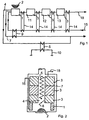
- Fig. 1 is a circuit diagram of an apparatus for generating Hydrogen shown for the operation of fuel cells.
- This consists among other things of a reformer 1 for conversion of hydrocarbon gas and water in hydrogen and others Reformer products, with the reformer 1 for deployment a defined process heat quantity with a burner Heat source 2 is provided and the reformer 1 Reaction-specific for the chemical processing of the reformer products adapted, heat-emitting catalyst stages 3 downstream are.
- the burner comes, as shown, preferably a hemispherical gas surface burner is used.
- the three catalyst stages shown are typically around the so-called high temperature 11 and Low-temperature shift stage 12 and SelOx stage 13; just like that but well combined shift levels are also good usable.
- Heat exchangers 14 are located between the individual catalyst stages arranged, on the one hand for the necessary cooling of the Heat-giving shift levels and the other hand serve, the starting materials hydrocarbon gas and water before Preheat entry to reformer 1.
- Fig. 1 With regard to the apparatus shown in Fig. 1 is the inventive Teaching realizes that as the burner trained and provided with a first exhaust gas 7 heat source 2 is connected to a second exhaust duct 4, the designed to be closable as required and with at least a heat exchanger 5 for the defined coupling of the if necessary additionally released amount of heat is provided.
- the Flap 8 is in accordance with the preferred embodiment 2 is arranged between the burner and the heat exchanger 5, so that when the flap 8 is closed the first Power burner working at its heat level exclusively for the reform process, while in a large part of the heating gases at a second power level opened flap 8 directly, and without the reforming process to be involved, the heating circuit 10 is supplied.
- the second The power level corresponds to the burner operation to a certain extent of a typical boiler connected to a reformer process to generate hydrogen.
- both the reformer 1 and the catalyst stages 3 are annular and at least partially the second Enclose exhaust duct 4 concentrically.
- the first exhaust duct 7 is completely closable, so that the exhaust gas coming from the burner is either completely the first 7, the second 4 or divided as needed both exhaust ducts 4, 7 can be removed.
- an adjustable flap 19 is arranged with which in in a first position the second exhaust gas duct 4 and in a second Position of the first exhaust gas duct 7 completely closable (indicated by dashed lines) and with the in a variable intermediate position - As shown - the exhaust on both flues 4, 7 can be divided as required.
- the hot exhaust gas flows from burner 2 first towards the flap 19. There it will, depending on the flap position divided on the exhaust gas ducts 4, 7, with the closed Flue gas duct 7 also a pure heating operation without hydrogen generation and thus fuel cell operation possible is.
- the exhaust gas duct 4 is closed, the exhaust gas flows against it only on the side of reformer 1 and shift stages 3 past. As in Fig. 2, the starting materials for the reformer Supply port 15 supplied. Closes at shift levels 3 a product discharge connection 18.
Landscapes
- Chemical & Material Sciences (AREA)
- Chemical Kinetics & Catalysis (AREA)
- Organic Chemistry (AREA)
- Health & Medical Sciences (AREA)
- General Health & Medical Sciences (AREA)
- Engineering & Computer Science (AREA)
- Combustion & Propulsion (AREA)
- Inorganic Chemistry (AREA)
- Hydrogen, Water And Hydrids (AREA)
Abstract
Description
- Fig. 1
- einen Schaltplan einer Ausführungsform mit einem zweiten Abgaszug zur Auskopplung der zusätzlich eingebrachten Wärmeleistung;
- Fig. 2
- eine mögliche konstruktive Gestaltung des Apparats gemäß Fig. 1 mit Klappe am zweiten Abgaszug; und
- Fig. 3
- eine weitere Ausführungsform mit Stellklappe zur bedarfsangepaßten Aufteilung des Abgasstromes.
- 1
- Reformer
- 2
- Wärmequelle
- 3
- Katalysatorstufen
- 4
- Abgaszug
- 5
- Wärmetauscher
- 6
- Wärmetauscher
- 7
- Abgaszug
- 8
- Klappe
- 9
- Wärmetauscher
- 10
- Heizkreis
- 11
- Hochtemperatur-Shiftstufe
- 12
- Niedertemperatur-Shiftstufe
- 13
- SelOx-Stufe
- 14
- Wärmetauscher
- 15
- Zufuhranschluss
- 16
- Wasseranschluss
- 17
- Abfuhranschluss
- 18
- Produktanschluss
- 19
- Klappe
- 20
- Abgasabzugskanal
Claims (8)
- Verfahren zum Betrieb eines Apparats zur Erzeugung von Wasserstoff zum Betrieb von Brennstoffzellen, bei dem einem Reformer (1) mit nachgeschalteten Katalysatorstufen (3) zur Umwandlung von Kohlenwasserstoffgas und Wasser in Wasserstoff und weitere Reformer-Produkte von einer als Brenner ausgebildeten Wärmequelle (2) eine definierte Prozesswärmemenge zugeführt wird, wobei im Bedarfsfall mittels der Wärmequelle (2) neben der erforderlichen Prozesswärmemenge eine zusätzliche Wärmemenge freisetzbar ist, die dem Apparat bezüglich des Reformerprozesses beeinträchtigungsfrei entzogen wird und einem separaten Verwendungszweck zuführbar ist,
dadurch gekennzeichnet, dass im Bedarfsfall ein zusätzlicher Abgaszug (4) definiert geöffnet wird, um die zusätzlich freigesetzte Wärmemenge bezüglich des Reformerprozesses beeinträchtigungsfrei mittels eines im Abgaszug (4) angeordneten Wärmetauschers (5) auszukoppeln. - Apparat zur Erzeugung von Wasserstoff zum Betrieb von Brennstoffzellen, umfassend einen Reformer (1) zur Umwandlung von Kohlenwasserstoffgas und Wasser in Wasserstoff und weitere Reformer-Produkte, wobei der Reformer (1) zur Bereitstellung einer definierten Prozesswärmemenge mit einer als Brenner ausgebildeten Wärmequelle (2) versehen ist und wobei dem Reformer (1) zur chemischen Aufbereitung der Reformer-Produkte reaktionsspezifisch angepaßte, wärmeabgebende Katalysatorstufen (3) nachgeschaltet sind, wobei die Wärmequelle (2) bezüglich der tatsächlich zur Reformierung erforderlichen Prozesswärmemenge überdimensioniert ausgelegt ist und am Apparat Mittel zur bezüglich der Reformierung beeinträchtigungsfreien Auskopplung einer im Bedarfsfall erzeugten zusätzlichen Wärmemenge vorgesehen sind,
dadurch gekennzeichnet, dass die mit einem ersten Abgaszug (7) versehene Wärmequelle (2) mit einem zweiten Abgaszug (4) in Verbindung steht, der bedarfsangepaßt verschliessbar ausgebildet und mit mindestens einem Wärmetauscher (5) zur definierten Auskopplung der im Bedarfsfall zusätzlich freigesetzten Wärmemenge versehen ist. - Apparat nach Anspruch 2,
dadurch gekennzeichnet, dass sowohl der Reformer (1) als auch die Katalysatorstufen (3) ringförmig ausgebildet sind und zumindest teilweise den zweiten Abgaszug (4) konzentrisch umschließen. - Apparat nach Anspruch 3,
dadurch gekennzeichnet, dass der zweite Abgaszug (4) mittels einer schwenkbaren Klappe (8) verschliessbar ausgebildet ist. - Apparat nach Anspruch 4,
dadurch gekennzeichnet, dass die Klappe (8) zwischen der als Brenner ausgebildeten Wärmequelle (2) und dem mindestens einen im zweiten Abgaszug (4) angeordneten Wärmetauscher (5) angeordnet ist. - Apparat nach einem der Ansprüche 2 bis 5,
dadurch gekennzeichnet, dass der erste Abgaszug (7) zur Vorwärmung des Kohlenwasserstoffgases und des Wassers mit einem Wärmetauscher (9) versehen ist. - Apparat nach einem der Ansprüche 2 bis 6,
dadurch gekennzeichnet, dass der erste Abgaszug (7) verschließbar ausgebildet ist, so dass vom Brenner kommendes Abgas wahlweise vollständig über den ersten (7), den zweiten (4) oder nach Bedarf aufgeteilt über beide Abgaszüge (4, 7) abführbar ist. - Apparat nach Anspruch 7,
dadurch gekennzeichnet, dass am Apparat eine verstellbare Klappe (19) vorgesehen ist, mit der in einer ersten Stellung der zweite Abgaszug (4) und in einer zweiten Stellung der erste Abgaszug (7) vollständig verschließbar und mit der in einer variablen Zwischenstellung das Abgas auf beide Abgaszüge (4, 7) bedarfsangepaßt aufteilbar ist.
Applications Claiming Priority (2)
| Application Number | Priority Date | Filing Date | Title |
|---|---|---|---|
| DE10149987 | 2001-10-11 | ||
| DE10149987A DE10149987A1 (de) | 2001-10-11 | 2001-10-11 | Verfahren zum Betrieb eines Apparats zur Erzeugung von Wasserstoff und Apparat zur Durchführung des Verfahrens |
Publications (2)
| Publication Number | Publication Date |
|---|---|
| EP1304311A2 true EP1304311A2 (de) | 2003-04-23 |
| EP1304311A3 EP1304311A3 (de) | 2003-07-09 |
Family
ID=7702047
Family Applications (1)
| Application Number | Title | Priority Date | Filing Date |
|---|---|---|---|
| EP02022623A Withdrawn EP1304311A3 (de) | 2001-10-11 | 2002-10-09 | Verfahren zum Betrieb eines Apparates zur Erzeugung von Wasserstoff sowie Apparat zur Erzeugung von Wasserstoff für Brennstoffzellen |
Country Status (2)
| Country | Link |
|---|---|
| EP (1) | EP1304311A3 (de) |
| DE (1) | DE10149987A1 (de) |
Cited By (1)
| Publication number | Priority date | Publication date | Assignee | Title |
|---|---|---|---|---|
| DE102004002477A1 (de) * | 2004-01-16 | 2005-08-11 | Viessmann Werke Gmbh & Co Kg | Vorrichtung zur Erzeugung von Wasserstoff |
Family Cites Families (10)
| Publication number | Priority date | Publication date | Assignee | Title |
|---|---|---|---|---|
| US4128700A (en) * | 1977-11-26 | 1978-12-05 | United Technologies Corp. | Fuel cell power plant and method for operating the same |
| DE2821413A1 (de) * | 1978-05-16 | 1979-11-22 | Texaco Development Corp | Teiloxydationsverfahren |
| DE3414140A1 (de) * | 1984-04-14 | 1985-10-24 | M.A.N. Maschinenfabrik Augsburg-Nürnberg AG, 8000 München | Verfahren und vorrichtung zum betreiben eines vergasungsreaktors |
| US4670359A (en) * | 1985-06-10 | 1987-06-02 | Engelhard Corporation | Fuel cell integrated with steam reformer |
| JP3297246B2 (ja) * | 1995-04-14 | 2002-07-02 | 三菱重工業株式会社 | 熱併給発電方法 |
| DK0818840T3 (da) * | 1996-07-11 | 2002-06-17 | Sulzer Hexis Ag | Fremgangsmåde til samtidig frembringelse af elektrisk energi og varme til opvarmningsformål |
| KR100501481B1 (ko) * | 1997-06-09 | 2005-09-26 | 에어 워터 가부시키가이샤 | 가스발생장치및그를사용한가스발생방법 |
| US5985474A (en) * | 1998-08-26 | 1999-11-16 | Plug Power, L.L.C. | Integrated full processor, furnace, and fuel cell system for providing heat and electrical power to a building |
| US6162267A (en) * | 1998-12-11 | 2000-12-19 | Uop Llc | Process for the generation of pure hydrogen for use with fuel cells |
| DE10057537A1 (de) * | 2000-11-20 | 2002-06-06 | Viessmann Werke Kg | Apparat zur Erzeugung von Wasserstoff |
-
2001
- 2001-10-11 DE DE10149987A patent/DE10149987A1/de not_active Ceased
-
2002
- 2002-10-09 EP EP02022623A patent/EP1304311A3/de not_active Withdrawn
Cited By (2)
| Publication number | Priority date | Publication date | Assignee | Title |
|---|---|---|---|---|
| DE102004002477A1 (de) * | 2004-01-16 | 2005-08-11 | Viessmann Werke Gmbh & Co Kg | Vorrichtung zur Erzeugung von Wasserstoff |
| US7632778B2 (en) | 2004-01-16 | 2009-12-15 | Süd-Chemie AG | Device for the generation of hydrogen |
Also Published As
| Publication number | Publication date |
|---|---|
| DE10149987A1 (de) | 2003-04-30 |
| EP1304311A3 (de) | 2003-07-09 |
Similar Documents
| Publication | Publication Date | Title |
|---|---|---|
| EP0818840B1 (de) | Verfahren zur gleichzeitigen Erzeugung von elektrischer Energie und Wärme für Heizzwecke | |
| DE10211354B4 (de) | Brennstoffreformer | |
| WO1999010628A1 (de) | Dampferzeuger, insbesondere abhitzedampferzeuger, und verfahren zum betrieb dieses dampferzeugers | |
| EP0926755A1 (de) | Brennstoffzellenmodul mit integrierter Zusatzheizung | |
| EP0924161A3 (de) | Verfahren zum Betrieb einer Wasserdampfreformierungsanlage, damit betreibbare Reformierungsanlage und Brennstoffzellensystembetriebsverfahren | |
| DE102009059310A1 (de) | Hocheffizientes Verfahren zur katalytischen Methanisierung von Kohlendioxid und Wasserstoff enthaltenden Gasgemischen | |
| EP0780917A1 (de) | Vorrichtung mit Brennstoffzellen | |
| WO2010051900A1 (de) | Prozessgaserzeugung mittels wärmerückgewinnung aus niedertemperaturabwärme | |
| DE10057537A1 (de) | Apparat zur Erzeugung von Wasserstoff | |
| EP3898505B1 (de) | Verfahren zur kohlenwasserstoffpyrolyse mit räumlich getrennter beheizungs- und reaktionszone innerhalb des reaktorraums | |
| EP3516179B1 (de) | Verfahren und anordnung zur wärmeenergierückgewinnung in anlagen umfassend wenigstens einen reformer | |
| DE102011100417A1 (de) | Reformer | |
| EP1304311A2 (de) | Verfahren zum Betrieb eines Apparates zur Erzeugung von Wasserstoff sowie Apparat zur Erzeugung von Wasserstoff für Brennstoffzellen | |
| DE60221476T2 (de) | Pyrolyseofen mit neuartiger Wärmezufuhr und Verfahren zum Cracken bei hohen Temperaturen mit demselben | |
| DE10160834B4 (de) | Vorrichtung zum Verdampfen und Überhitzen wenigstens eines Mediums sowie Brennstoffzellensystem | |
| DE10007574C2 (de) | Verfahren zur Wärmeübertragung zwischen mindestens drei Wärmeträgermedien und Wärmeübertrager zur Durchführung dieses Verfahrens | |
| DE20215522U1 (de) | Apparat zur Erzeugung von Wasserstoff | |
| DE69901799T2 (de) | Verfahren und vorrichtung zur herstellung von ammonia | |
| DE10111072B4 (de) | Anlage zur Erzeugung von Strom und Wärme | |
| EP1304310A2 (de) | Verfahren und Vorrichtung zur Reformierung flüssiger Kohlenwasserstoffgemische | |
| DE19955892A1 (de) | Verfahren und Vorrichtung zur Reformierung eines Kohlenwasserstoffs mit langkettigen Kohlenwasserstoffanteilen | |
| DE102007018311B4 (de) | Zweistufiger Reformer und Verfahren zum Betreiben eines Reformers | |
| DE102008009063A1 (de) | Brennstoffzellensystem | |
| DE102004001310A1 (de) | Verfahren zum Betrieb einer Anlage zur Wasserdampfreformierung eines Kohlenwasserstoffgases | |
| BE1030484B1 (de) | Wärmetauscher mit integrierter Anfahrheizung |
Legal Events
| Date | Code | Title | Description |
|---|---|---|---|
| PUAI | Public reference made under article 153(3) epc to a published international application that has entered the european phase |
Free format text: ORIGINAL CODE: 0009012 |
|
| AK | Designated contracting states |
Designated state(s): AT BE BG CH CY CZ DE DK EE ES FI FR GB GR IE IT LI LU MC NL PT SE SK TR |
|
| AX | Request for extension of the european patent |
Extension state: AL LT LV MK RO SI |
|
| PUAL | Search report despatched |
Free format text: ORIGINAL CODE: 0009013 |
|
| AK | Designated contracting states |
Designated state(s): AT BE BG CH CY CZ DE DK EE ES FI FR GB GR IE IT LI LU MC NL PT SE SK TR |
|
| AX | Request for extension of the european patent |
Extension state: AL LT LV MK RO SI |
|
| 17P | Request for examination filed |
Effective date: 20031217 |
|
| AKX | Designation fees paid |
Designated state(s): AT BE BG CH CY CZ DE DK EE ES FI FR GB GR IE IT LI LU MC NL PT SE SK TR |
|
| RAP1 | Party data changed (applicant data changed or rights of an application transferred) |
Owner name: VIESSMANN WERKE GMBH & CO KG |
|
| 17Q | First examination report despatched |
Effective date: 20041108 |
|
| STAA | Information on the status of an ep patent application or granted ep patent |
Free format text: STATUS: THE APPLICATION HAS BEEN WITHDRAWN |
|
| 18W | Application withdrawn |
Effective date: 20101130 |