EP1304259A2 - Lever switch for vehicle - Google Patents
Lever switch for vehicle Download PDFInfo
- Publication number
- EP1304259A2 EP1304259A2 EP02023118A EP02023118A EP1304259A2 EP 1304259 A2 EP1304259 A2 EP 1304259A2 EP 02023118 A EP02023118 A EP 02023118A EP 02023118 A EP02023118 A EP 02023118A EP 1304259 A2 EP1304259 A2 EP 1304259A2
- Authority
- EP
- European Patent Office
- Prior art keywords
- rotating shaft
- recessed portion
- lever
- casing
- control lever
- Prior art date
- Legal status (The legal status is an assumption and is not a legal conclusion. Google has not performed a legal analysis and makes no representation as to the accuracy of the status listed.)
- Granted
Links
Images


Classifications
-
- B—PERFORMING OPERATIONS; TRANSPORTING
- B60—VEHICLES IN GENERAL
- B60Q—ARRANGEMENT OF SIGNALLING OR LIGHTING DEVICES, THE MOUNTING OR SUPPORTING THEREOF OR CIRCUITS THEREFOR, FOR VEHICLES IN GENERAL
- B60Q1/00—Arrangement of optical signalling or lighting devices, the mounting or supporting thereof or circuits therefor
- B60Q1/02—Arrangement of optical signalling or lighting devices, the mounting or supporting thereof or circuits therefor the devices being primarily intended to illuminate the way ahead or to illuminate other areas of way or environments
- B60Q1/04—Arrangement of optical signalling or lighting devices, the mounting or supporting thereof or circuits therefor the devices being primarily intended to illuminate the way ahead or to illuminate other areas of way or environments the devices being headlights
- B60Q1/14—Arrangement of optical signalling or lighting devices, the mounting or supporting thereof or circuits therefor the devices being primarily intended to illuminate the way ahead or to illuminate other areas of way or environments the devices being headlights having dimming means
- B60Q1/1446—Arrangement of optical signalling or lighting devices, the mounting or supporting thereof or circuits therefor the devices being primarily intended to illuminate the way ahead or to illuminate other areas of way or environments the devices being headlights having dimming means controlled by mechanically actuated switches
- B60Q1/1453—Hand actuated switches
- B60Q1/1461—Multifunction switches for dimming headlights and controlling additional devices, e.g. for controlling direction indicating lights
- B60Q1/1469—Multifunction switches for dimming headlights and controlling additional devices, e.g. for controlling direction indicating lights controlled by or attached to a single lever, e.g. steering column stalk switches
Definitions
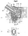
- the wire lead 11 can be mounted into the recessed portion 24b through the gap 24i, and also the wire lead 11 can be retained in the recessed portion 24b with the tongue pieces 24h, thus further improving workability during assembly.
Landscapes
- Engineering & Computer Science (AREA)
- Mechanical Engineering (AREA)
- Switches With Compound Operations (AREA)
- Mechanisms For Operating Contacts (AREA)
Abstract
Description
Claims (5)
- A lever switch for a vehicle comprising a control lever in which switches are housed in an operating section thereof, a swing block, and a casing, the control lever being rotatably retained by said swing block, said swing block having a rotating shaft formed on the bottom wall thereof, the rotating shaft being fitted in a shaft hole of said casing to be supported by the casing, and said control lever being allowed to rotate in two intersecting planes with respect to said casing, wherein:a recessed portion communicating with said control lever is formed in the outer peripheral face of said rotating shaft or the inner peripheral face of said shaft hole.
- A lever switch for a vehicle of claim 1, wherein said recessed portion is formed in said rotating shaft and extends from the upper end face of said bottom wall to the lower end face of said rotating shaft.
- A lever switch for a vehicle of claim 2, wherein said recessed portion has a retaining section for retaining wire leads.
- A lever switch for a vehicle of claim 3, wherein said retaining section is constituted by tongue pieces formed at an opening of said recessed portion, extending as part of said rotating shaft.
- A lever switch for a vehicle of claim 3, wherein said retaining section is constituted by a plurality of grooves formed in parallel with said recessed portion in the recessed portion.
Applications Claiming Priority (2)
| Application Number | Priority Date | Filing Date | Title |
|---|---|---|---|
| JP2001319283 | 2001-10-17 | ||
| JP2001319283A JP3944376B2 (en) | 2001-10-17 | 2001-10-17 | Lever switch for vehicle |
Publications (3)
| Publication Number | Publication Date |
|---|---|
| EP1304259A2 true EP1304259A2 (en) | 2003-04-23 |
| EP1304259A3 EP1304259A3 (en) | 2004-01-21 |
| EP1304259B1 EP1304259B1 (en) | 2005-04-27 |
Family
ID=19136857
Family Applications (1)
| Application Number | Title | Priority Date | Filing Date |
|---|---|---|---|
| EP02023118A Expired - Lifetime EP1304259B1 (en) | 2001-10-17 | 2002-10-15 | Lever switch for vehicle |
Country Status (4)
| Country | Link |
|---|---|
| US (1) | US6624366B2 (en) |
| EP (1) | EP1304259B1 (en) |
| JP (1) | JP3944376B2 (en) |
| DE (1) | DE60203864T2 (en) |
Cited By (1)
| Publication number | Priority date | Publication date | Assignee | Title |
|---|---|---|---|---|
| EP1607268A1 (en) * | 2004-06-17 | 2005-12-21 | Sc2N | Mechanical indexing, especially for an electrical switch |
Families Citing this family (5)
| Publication number | Priority date | Publication date | Assignee | Title |
|---|---|---|---|---|
| JP2003263938A (en) * | 2002-03-07 | 2003-09-19 | Matsushita Electric Ind Co Ltd | Lever switch and composite switch using the same |
| DE102005038145A1 (en) * | 2005-08-12 | 2007-02-15 | Leopold Kostal Gmbh & Co. Kg | steering column module |
| JP4232796B2 (en) * | 2005-11-29 | 2009-03-04 | セイコーエプソン株式会社 | Robot control apparatus and robot system |
| JP2008192559A (en) * | 2007-02-07 | 2008-08-21 | Alps Electric Co Ltd | On-vehicle knob switch |
| US10100919B1 (en) * | 2016-06-10 | 2018-10-16 | Kongsberg Power Products Systems I, Inc. | Shifter assembly |
Family Cites Families (9)
| Publication number | Priority date | Publication date | Assignee | Title |
|---|---|---|---|---|
| JPS57162142A (en) * | 1981-03-27 | 1982-10-05 | Hitachi Ltd | Tracking error detector for magnetic video recording and reproducing device |
| JPS58173533U (en) * | 1982-04-23 | 1983-11-19 | 株式会社東海理化電機製作所 | Automobile speed control switch device |
| JP3038639B2 (en) * | 1994-03-30 | 2000-05-08 | ナイルス部品株式会社 | Assembly structure of lever switch |
| US5581058A (en) * | 1995-02-03 | 1996-12-03 | United Technologies Automotive, Inc. | Multifunction switch stalk for controlling vehicle functions |
| JP3565388B2 (en) * | 1996-11-26 | 2004-09-15 | ナイルス株式会社 | Structure of vehicle lever switch |
| JPH10241504A (en) * | 1997-02-24 | 1998-09-11 | Yazaki Corp | Signal transmission device for steering |
| JP2000195380A (en) * | 1998-12-25 | 2000-07-14 | Niles Parts Co Ltd | Harness-fixing structure |
| US6114640A (en) * | 1999-03-01 | 2000-09-05 | Daimlerchrysler Corporation | Vehicle column stalk functionality |
| JP4629854B2 (en) * | 2000-11-14 | 2011-02-09 | ナイルス株式会社 | Combination switch for vehicle |
-
2001
- 2001-10-17 JP JP2001319283A patent/JP3944376B2/en not_active Expired - Lifetime
-
2002
- 2002-10-15 DE DE60203864T patent/DE60203864T2/en not_active Expired - Lifetime
- 2002-10-15 EP EP02023118A patent/EP1304259B1/en not_active Expired - Lifetime
- 2002-10-16 US US10/270,588 patent/US6624366B2/en not_active Expired - Lifetime
Cited By (2)
| Publication number | Priority date | Publication date | Assignee | Title |
|---|---|---|---|---|
| EP1607268A1 (en) * | 2004-06-17 | 2005-12-21 | Sc2N | Mechanical indexing, especially for an electrical switch |
| FR2871927A1 (en) * | 2004-06-17 | 2005-12-23 | Sc2N Sa | MECHANICAL INDEXING SYSTEM, IN PARTICULAR FOR AN ELECTRIC SWITCH |
Also Published As
| Publication number | Publication date |
|---|---|
| JP3944376B2 (en) | 2007-07-11 |
| DE60203864D1 (en) | 2005-06-02 |
| DE60203864T2 (en) | 2006-01-26 |
| JP2003123595A (en) | 2003-04-25 |
| EP1304259A3 (en) | 2004-01-21 |
| US6624366B2 (en) | 2003-09-23 |
| EP1304259B1 (en) | 2005-04-27 |
| US20030079975A1 (en) | 2003-05-01 |
Similar Documents
| Publication | Publication Date | Title |
|---|---|---|
| EP0939009A2 (en) | Lever switch for vehicles | |
| EP0976611B1 (en) | Construction of an on-vehicle lever switch | |
| KR20050034425A (en) | Steering wheel remocone switch button for vehicle | |
| EP1304259B1 (en) | Lever switch for vehicle | |
| US6624364B2 (en) | Multifunction stalk-mounted switch | |
| US6872897B2 (en) | Switch contact structure | |
| EP2232517B1 (en) | Switch lever for vehicle | |
| KR102304847B1 (en) | Multi-Function Switch for vehicle | |
| EP1655754B1 (en) | Automotive combination switch | |
| KR100253490B1 (en) | Vehicle Lever Switch Structure | |
| US20030038019A1 (en) | Steering column stalk having multiple switch cells | |
| CN100533626C (en) | Toggle switch | |
| JPH0922641A (en) | Structure of vehicular lever switch | |
| JP2000260265A (en) | Stalk lever | |
| EP1304713B1 (en) | Switch contact structure | |
| EP1739792B1 (en) | Circuit unit device | |
| JP2007035461A (en) | Electric component | |
| JP3170187B2 (en) | Steering column switch | |
| JPH10241505A (en) | Lever switch apparatus | |
| JP4137230B2 (en) | Mounting structure for movable contact of washer switch | |
| JP2007287410A (en) | Operation switch device | |
| KR100658043B1 (en) | Wiper switch device | |
| JP2008130497A (en) | Switching device | |
| KR100371713B1 (en) | Multi function switch for an automobile | |
| KR20230011724A (en) | Head lamp leveling device for vehicle |
Legal Events
| Date | Code | Title | Description |
|---|---|---|---|
| PUAI | Public reference made under article 153(3) epc to a published international application that has entered the european phase |
Free format text: ORIGINAL CODE: 0009012 |
|
| AK | Designated contracting states |
Designated state(s): AT BE BG CH CY CZ DE DK EE ES FI FR GB GR IE IT LI LU MC NL PT SE SK TR |
|
| AX | Request for extension of the european patent |
Extension state: AL LT LV MK RO SI |
|
| PUAL | Search report despatched |
Free format text: ORIGINAL CODE: 0009013 |
|
| AK | Designated contracting states |
Kind code of ref document: A3 Designated state(s): AT BE BG CH CY CZ DE DK EE ES FI FR GB GR IE IT LI LU MC NL PT SE SK TR |
|
| AX | Request for extension of the european patent |
Extension state: AL LT LV MK RO SI |
|
| 17P | Request for examination filed |
Effective date: 20040720 |
|
| AKX | Designation fees paid |
Designated state(s): DE FR GB |
|
| GRAP | Despatch of communication of intention to grant a patent |
Free format text: ORIGINAL CODE: EPIDOSNIGR1 |
|
| GRAS | Grant fee paid |
Free format text: ORIGINAL CODE: EPIDOSNIGR3 |
|
| GRAA | (expected) grant |
Free format text: ORIGINAL CODE: 0009210 |
|
| AK | Designated contracting states |
Kind code of ref document: B1 Designated state(s): DE FR GB |
|
| REG | Reference to a national code |
Ref country code: GB Ref legal event code: FG4D |
|
| REG | Reference to a national code |
Ref country code: IE Ref legal event code: FG4D |
|
| REF | Corresponds to: |
Ref document number: 60203864 Country of ref document: DE Date of ref document: 20050602 Kind code of ref document: P |
|
| PLBE | No opposition filed within time limit |
Free format text: ORIGINAL CODE: 0009261 |
|
| STAA | Information on the status of an ep patent application or granted ep patent |
Free format text: STATUS: NO OPPOSITION FILED WITHIN TIME LIMIT |
|
| ET | Fr: translation filed | ||
| 26N | No opposition filed |
Effective date: 20060130 |
|
| PGFP | Annual fee paid to national office [announced via postgrant information from national office to epo] |
Ref country code: GB Payment date: 20131022 Year of fee payment: 12 Ref country code: DE Payment date: 20130713 Year of fee payment: 12 Ref country code: FR Payment date: 20131018 Year of fee payment: 12 |
|
| REG | Reference to a national code |
Ref country code: DE Ref legal event code: R082 Ref document number: 60203864 Country of ref document: DE Representative=s name: MAI, OPPERMANN & PARTNER I. L., DE Ref country code: DE Ref legal event code: R082 Ref document number: 60203864 Country of ref document: DE Representative=s name: OANDO OPPERMANN & OPPERMANN LLP, DE |
|
| REG | Reference to a national code |
Ref country code: DE Ref legal event code: R082 Ref document number: 60203864 Country of ref document: DE Representative=s name: OANDO OPPERMANN & OPPERMANN LLP, DE |
|
| REG | Reference to a national code |
Ref country code: DE Ref legal event code: R119 Ref document number: 60203864 Country of ref document: DE |
|
| GBPC | Gb: european patent ceased through non-payment of renewal fee |
Effective date: 20141015 |
|
| PG25 | Lapsed in a contracting state [announced via postgrant information from national office to epo] |
Ref country code: GB Free format text: LAPSE BECAUSE OF NON-PAYMENT OF DUE FEES Effective date: 20141015 Ref country code: DE Free format text: LAPSE BECAUSE OF NON-PAYMENT OF DUE FEES Effective date: 20150501 |
|
| REG | Reference to a national code |
Ref country code: FR Ref legal event code: ST Effective date: 20150630 |
|
| PG25 | Lapsed in a contracting state [announced via postgrant information from national office to epo] |
Ref country code: FR Free format text: LAPSE BECAUSE OF NON-PAYMENT OF DUE FEES Effective date: 20141031 |
|
| REG | Reference to a national code |
Ref country code: DE Ref legal event code: R082 Ref document number: 60203864 Country of ref document: DE Representative=s name: OANDO OPPERMANN & OPPERMANN LLP, DE |