EP1304233A2 - Apparatus and method for stuffing a folder - Google Patents
Apparatus and method for stuffing a folder Download PDFInfo
- Publication number
- EP1304233A2 EP1304233A2 EP02023402A EP02023402A EP1304233A2 EP 1304233 A2 EP1304233 A2 EP 1304233A2 EP 02023402 A EP02023402 A EP 02023402A EP 02023402 A EP02023402 A EP 02023402A EP 1304233 A2 EP1304233 A2 EP 1304233A2
- Authority
- EP
- European Patent Office
- Prior art keywords
- folder
- insert
- insert material
- stuffing
- Prior art date
- Legal status (The legal status is an assumption and is not a legal conclusion. Google has not performed a legal analysis and makes no representation as to the accuracy of the status listed.)
- Withdrawn
Links
Images


Classifications
-
- B—PERFORMING OPERATIONS; TRANSPORTING
- B65—CONVEYING; PACKING; STORING; HANDLING THIN OR FILAMENTARY MATERIAL
- B65H—HANDLING THIN OR FILAMENTARY MATERIAL, e.g. SHEETS, WEBS, CABLES
- B65H39/00—Associating, collating, or gathering articles or webs
- B65H39/02—Associating,collating or gathering articles from several sources
-
- B—PERFORMING OPERATIONS; TRANSPORTING
- B43—WRITING OR DRAWING IMPLEMENTS; BUREAU ACCESSORIES
- B43M—BUREAU ACCESSORIES NOT OTHERWISE PROVIDED FOR
- B43M5/00—Devices for closing envelopes
- B43M5/04—Devices for closing envelopes automatic
-
- B—PERFORMING OPERATIONS; TRANSPORTING
- B65—CONVEYING; PACKING; STORING; HANDLING THIN OR FILAMENTARY MATERIAL
- B65H—HANDLING THIN OR FILAMENTARY MATERIAL, e.g. SHEETS, WEBS, CABLES
- B65H45/00—Folding thin material
- B65H45/02—Folding limp material without application of pressure to define or form crease lines
- B65H45/04—Folding sheets
-
- B—PERFORMING OPERATIONS; TRANSPORTING
- B65—CONVEYING; PACKING; STORING; HANDLING THIN OR FILAMENTARY MATERIAL
- B65H—HANDLING THIN OR FILAMENTARY MATERIAL, e.g. SHEETS, WEBS, CABLES
- B65H45/00—Folding thin material
- B65H45/12—Folding articles or webs with application of pressure to define or form crease lines
- B65H45/18—Oscillating or reciprocating blade folders
-
- B—PERFORMING OPERATIONS; TRANSPORTING
- B65—CONVEYING; PACKING; STORING; HANDLING THIN OR FILAMENTARY MATERIAL
- B65H—HANDLING THIN OR FILAMENTARY MATERIAL, e.g. SHEETS, WEBS, CABLES
- B65H2301/00—Handling processes for sheets or webs
- B65H2301/40—Type of handling process
- B65H2301/43—Gathering; Associating; Assembling
- B65H2301/435—Gathering; Associating; Assembling on collecting conveyor
- B65H2301/4351—Gathering; Associating; Assembling on collecting conveyor receiving articles astride thereon
Definitions
- the present invention relates generally to stuffing folders. More particularly, the present invention relates to an apparatus and method for automatically stuffing folder pockets.
- U.S. Patent No. 4,055,932 to Wanner discloses an envelope stuffing machine adapted to insert sheets of paper or the like between the sides of a cover which can be drawn apart by suction to accommodate the sheets.
- the device further comprises a pair of opposite perforated surfaces connected to a suction chamber and between which the envelope is introduced so as to draw the opposite sides of the envelope apart to receive the sheets to be inserted.
- U.S. Patent No. 3,999,701 to Ward discusses a currency-holding packet and a method of forming the packet and inserting bills of currency into the packet using prior art envelope stuffers.
- Katz et al. discloses a system for producing a mass distributable packet wherein a web of paper is provided and cut to form sheets. The sheets are then accumulated and stacked in a hopper and the bottom sets are successively removed and packaged in a standard envelope inserter.
- Linder describes a device to insert printed products into an envelope using a rotating conveying member that is equipped with receiving pockets that are distributed over its circumference and can be closed and opened.
- U.S. Patent No. 4,295,643 to de la Vega disclose devices for the transporting and inserting of flat products.
- U.S. Patent No. 5,823,320 to Seidel et al. disclose devices for the transporting and inserting of flat products.
- Each of the references is directed to devices which may be used for the transportation of newspaper jackets and insertion of various supplemental materials therein.
- An automated folder stuffing apparatus and method for stuffing a folder of the type that is foldable along a fold line and includes an inside surface and at least one pocket formed on the inside surface.
- the folder stuffing apparatus includes a conveyor for advancing a folder along a conveying surface of the conveyor, an opener for at least partially opening a pocket of the folder, and an inserter for inserting insert material into the folder pocket while the pocket is open.
- the conveyor surface can further include a plurality of vacuum ports and the conveyor can further include a rotatable endless member and a pusher element for engaging and advancing the folder along the conveyor surface.
- the inserter can further include an insert carriage member slidable along an insert track for releasably engaging the insert material and directing the insert material into the opened pocket. Readers can be included and utilized at various positions for reading data code, which can be on the insert material and even the folders, and the data read can be used to process items in a predetermined manner.
- a method for stuffing insert material into a pocket of a folder includes advancing a folder along a conveyor surface while an outside surface of the folder slidably contacts the conveyor surface and a pocket of the folder faces outwardly in relation to the conveyor surface.
- the method further includes at least partially opening the folder pocket with an opener when the folder has reached an insertion site of the conveyor surface and inserting insert material into the folder pocket while the folder is at the insertion point.
- the insert material and even the folders can include data codes thereon which can be used for controlling various steps of processing as desired to ensure the integrity of assembled stuffed folders.
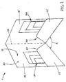
- Folder F includes an outside surface generally designated 20 , an inside surface generally designated 22 , and a fold line 24 that runs down the middle of folder F , preferably separating both sides equally.
- the left side of folder F has a left inside panel 26 and a left flap 28 , wherein the void defined between left inside panel 26 and left flap 28 is the left pocket generally designated LP .
- the right side of folder F has a right inside panel 26' and a right flap 28' , wherein the void defined between right inside panel 26' and right flap 28' is the right pocket, generally designated RP .
- Collated insert material such as, for example, left pocket insert material generally designated LM , and right pocket insert material generally designated RM , can be inserted into the appropriate pockets LP, RP of folder F as described further below.
- Folder F can be considered to be in a folded state when an angle A between left and right inside panels 26, 26' is less than 180 degrees, and can be considered to be in an open state when angle A is greater than 180 degrees.
- a folder such as folder F , of any suitable type with one or more pockets LP, RP can be automatically stuffed with accumulated pocket insert materials LM, RM , folded, and conveyed to a final destination for distribution.
- Stuffing can occur downstream of a device that is capable of transporting pre-collated material, typically collated by other mechanical means, such as by using push pins located along a transport surface.
- Primary product material such as sheets, pamphlets, booklets, etc., can be received generally along a material feed or flow direction from an upstream location into the folder stuffing apparatus.
- primary product material can be collated into left pocket insert material LM and right pocket insert material RM .
- Left pocket insert material LM and right pocket insert material RM can each constitute a different predetermined combination of primary product material (e.g., one or more individual sheets, a stapled set of sheets, cards, booklets, etc.) as desired by the user for stuffing left folder pocket LP or right folder pocket RP .
- Left pocket insert material LM and right pocket insert material RM can be conveyed in a manner in which they will alternate along the transport surface when moving towards the folder stuffing apparatus, such that left pocket insert material LM to be stuffed in left folder pocket LP will be followed by right pocket insert material RM to be stuffed in right folder pocket RP , and this series can repeat for sets 3 and 4, 5 and 6, etc. It is also envisioned that if a user desires to stuff only one pocket of folder F , such as, for example, right folder pocket RP , only right pocket insert material RM will be produced in a series for stuffing the right folder pocket RP .
- Folder F to be stuffed can enter the folder stuffing apparatus by way of a separate conveyor that advances folder F along a conveying surface wherein folder F is in an open state.
- left pocket insert material LM can enter a Stage 1 position where it can be mechanically stuffed into left folder pocket LP by a process to be described in more detail below.
- Right pocket insert material RM can pass through the Stage 1 position and enter a Stage 2 position where can be mechanically stuffed in a similar manner into right folder pocket RP .
- folder pockets LP RP are automatically stuffed with pocket insert materials LM, RM , respectively, and folder F is folded, the final product, a stuffed folder, can then be transferred to a downstream location generally along an exit or output direction.
- primary product material PM can comprise any documents suitable for assembly into a set of insert material and for stuffing into a folder as described above.
- primary product material PM comprises individual stacks of insert materials which can be fed from the side (preferably bound edge first and printed side face up for booklets, stapled sets of sheets, etc.) onto insert transport surface 42 to form assembled sets of materials, which can be left pocket insert material LM and right pocket insert material RM .
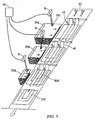
- one or more pieces of primary product material PM can include data code DC thereon, shown in FIG. 3 as bar codes.
- Data code DC can be positioned in any suitable location on primary product material PM and can include any suitable readable data for feeding or processing instructions or for matching with one or more folder F .
- Readers R can be used to read data code DC from primary product material PM at any point during processing, such as prior to advancement onto insert transport surface 42 , while being advanced onto insert transport surface 42 , or at any desirable stage of processing after advancement onto insert transport surface 42 . For exemplary purposes only, reading is illustrated in FIG. 3 as occurring as primary product material PM is being advanced onto insert transport surface 42 .
- Readers R communicate with a central or local microprocessor M for processing of read data code DC and for controlling the processing of primary product material PM .
- the read data from data code DC can be used for selectively feeding certain primary product material PM in a predetermined manner and facilitating accurate matching and stuffing of primary product material PM with folders such as folder F and for verifying the integrity of stuffed folders, as further described hereinbelow.
- left pocket insert material LM and right pocket insert material RM can be assembled in a staggered, alternating order one behind the other.
- the controlled in-feed of primary product material PM to form pocket insert materials LM, RM can be implemented by providing means for feeding primary product material PM in accordance with a repeatable (i.e., cyclical) profile.
- this profile can be programmed to enable primary product material PM to be fed in a manner creating left pocket insert material LM and right pocket insert material RM or can be programmed to only enable primary product material PM to be fed in a manner creating one set of either left pocket insert material LM or right pocket insert material RM (such as, for example, if only the right pocket RP of folder F is to be stuffed).
- This profile can be suitably adjusted according to user specifications.
- Left pocket insert material LM and right pocket insert material RM can be accumulated and formed in alternate sets along insert transport surface 42 as they are directed toward the folder stuffing module.
- each left pocket insert material LM and each right pocket insert material RM are all oriented in the same manner.
- each left pocket insert material LM can be inserted into left folder pocket LP of folder F such that the bound edge enters left folder pocket LP first and the non-bound edge last.
- each right pocket insert material RM can be inserted into right folder pocket RP of folder F such that the non-bound edge enters right folder pocket RP first and the bound edge last.
- both left pocket insert material LM and right pocket insert material RM are presented in folder F in the left-to-right orientation, thereby rendering left and right pocket insert materials LM and RM immediately and easily readable upon opening the stuffed folder F .
- Assembled pocket insert materials LM, RM can be pushed along insert transport surface 42 by push pins 44 or any other suitable form of conveying system known to those skilled in the art. Insert transport surface 42 can be further indexed with the use of registration straps 46 to ensure rear registration against push pins 44 as primary product material PM is fed and formed into pocket insert materials LM, RM . Registration straps 46 can be constructed of metal, cloth, plastic or any other suitable material known to those skilled in the art. After all requisite primary product material PM has been fed and pocket insert materials LM, RM have been completely formed, pocket insert materials LM, RM can be pushed downstream for further processing.
- folders F can be fed into a folder entry area generally designated 50 in an open position from any suitable direction.
- folders F can be provided from a direction that can be perpendicular or parallel to insert transport surface 42 (shown in Fig. 5) in order to ultimately be positioned on a folder conveyor assembly generally designated CA .
- folders F can include data code DC thereon, illustrated as bar code, which can include any suitable data for feeding or processing instructions or for matching folders F with certain, predetermined primary product material PM , such as for example assembled left pocket insert material LM and right pocket insert material RM .
- One or more readers R can be used to read data code DC from folders F at folder entry area 50 .
- Readers R can communicate with a central or local microprocessor M for processing of read data code DC and for controlling the processing of folders F .
- the data from each data code DC can be utilized in any suitable manner to identify and recognize folders F and to process them in a predetermined and controlled fashion. Desired folders F can be matched up with desired primary product material PM , such as left pocket insert material LM and/or right pocket insert material RM. Accurate stuffing and verification of the integrity of folders F can thus be accomplished.
- read data code from both folders F and primary product material PM enables automated stuffing of folders F wherein selected, predetermined folders F can be stuffed on demand and in a personalized manner with only selected, predetermined primary product material P M.
- Data code DC on primary pocket material PM and folders F can further be processed and used to determine what to do to certain folders F .
- instructions can be provided to selectively print or paint certain items on selected folders F , or instructions can be provided as to whether or not to stuff certain folders F at all as advanced pocket insert material and/or folders F can be selectively advanced without being stuffed as described further below with reference to FIG. 5.
- folder conveyor assembly CA is configured as an A-frame structure 52 having a first conveyor surface generally designated 52A and a second conveyor surface generally designated 52B wherein first and second conveyor surfaces 52A, 52B are joined at a common edge 53 and extend outwardly at an angle from common edge 53 relative to a base plane generally designated B.
- Conveyor assembly CA further comprises a conveyor consisting of, for example, an endless member 61 such as a chain or belt with pusher elements 62 such as grips or fingers, or any other conveying mechanism known to those skilled in the art.
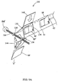
- folder F can enter folder entry area 50 and come to rest in a substantially flat position on a swivel plate SP , as shown in FIGS. 4A and 4B.
- Swivel plate SP is an invertible section comprising a central hinge 54 that allows swivel plate SP to pivot upwardly in the center.
- Swivel plate SP is further attached by appropriate linkages 55 to a rod-type linear actuator 56 , such as a ball screw that provides linear motion via a motor SM .
- Swivel plate SP can also comprise one or more vacuum ports 58 through which a vacuum can be applied as can be appreciated by those of skill in the art to suitably hold folder F to swivel plate SP during the upward motion of swivel plate SP .
- Folder F maintained in position on swivel plate SP , will also be drawn upwardly at folder fold line 24 thus drawing folder F from a substantially flat position to an inverted position with folder inside surface 22 facing outwardly and left and right folder inside panels 26, 26' substantially coplanar with first and second conveyor surfaces 52A, 52B.
- folder F can be conveyed onto A-frame 52 and moved downstream towards a Stage 1 position 70 (shown in FIG. 5) via endless member 61 and pusher elements 62 .
- Folder F can be advanced along A-frame 52 for further processing while folder F maintains an inverted state wherein folder inside surface 22 and folder left and right pockets LP, RP face outwardly in relation to first and second conveyor surfaces 52A, 52B.
- Two folder stuffing stages include a Stage 1 position 70 , where left folder pocket LP can be stuffed and a Stage 2 position 70' , where right folder pocket RP can be stuffed.
- Stage 1 position 70 where left folder pocket LP can be stuffed
- Stage 2 position 70' where right folder pocket RP can be stuffed.
- left pocket insert material LM and right pocket insert material RM that are to be stuffed into left folder pocket LP and right folder pocket RP , respectively, can be located above folder F that is carried along A-frame 52 .
- Insert material for entering folder stuffing stages 70, 70' can be read or otherwise recognized as consisting of left pocket insert material LM or right pocket insert material RM . If the insert material is left pocket insert material LM , it will be processed in Stage 1 position area 70 for stuffing into left folder pocket LP ; similarly, if the insert material is right pocket insert material RM , it will pass through Stage 1 position 70 and move further downstream to be processed in Stage 2 position area 70' for stuffing into right folder pocket RP . As discussed earlier, if a user desires that only one pocket of a two pocket folder F be filled (or if the user is stuffing a one pocket folder F ), the stage position that is not being used to fill a folder pocket can be intentionally by-passed.
- Stage 1 position 70 that normally stuffs left folder pocket LP can be by-passed such that Stage 2 position 70' to fill right folder pocket RP will only be activated and vice-versa.
- Stage 1 position 70 that normally stuffs left folder pocket LP can be by-passed such that Stage 2 position 70' to fill right folder pocket RP will only be activated and vice-versa.
- Each of the two folder stuffing stages 70, 70' described above can operate in a similar manner as will now be described in further detail below.
- side transporters ST, ST' can be activated.
- side transporters ST, ST' respectively, comprise endless belt systems 72, 72' with push pins 78, 78' or any other suitable conveying system as known to those skilled in the art and can be oriented transversely to insert transport surface 42 .
- Side transporters ST, ST' can activate to transfer applicable pocket insert materials LM, RM from insert transport surface 42 to insert carriage members generally designated 80, 80' .
- Insert carriage members 80, 80' can be slidably attached to insert track or guide rails 76, 76' such that insert carriage members 80, 80' and all associated mechanisms can move up and down guide rails 76, 76' as necessary, driven by motors M, M' (see FIG. 6).
- guide rails 76, 76' are configured so that insert carriage members 80, 80' are slidable along guide rails 76, 76' through an insert path that is substantially coplanar with first and second conveyor surfaces 52A, 52B, respectively.
- Insert carriage member 80 used in Stage 1 position 70, is shown in FIGS. 7 and 8, with an isolated view illustrated in FIG. 8.
- Insert carriage member 80' (shown in FIGS. 6 and 7) used in Stage 2 position 70' can be similarly configured.
- Insert carriage members 80, 80' can comprise clamp plates 82, 82' that are attached to registration platters 74, 74' by clamp plate solenoids 84, 84' .
- Clamp plate solenoids 84, 84' allow clamp plates 82, 82' to be raised and lowered onto pocket insert materials LM, RM , thus catching pocket insert materials LM, RM in a secured manner between clamp plates 82, 82' and registration platters 74, 74' , respectively.
- stage pocket insert materials LM, RM in this manner facilitates the synchronization of the operation of insert carriage members 80, 80' with other operative components of folder stuffing apparatus 10 , such as pocket opening vacuum solenoids 86, 86' described hereinbelow.
- push pins 78, 78' that are attached to the drive belts of endless belt systems 72, 72' can contact the applicable pocket insert materials LM, RM and transfer them in a transverse direction off of insert transport surface 42 and onto registration platters 74, 74' of insert carriage members 80, 80' .
- Push pins 78, 78' will push pocket insert materials LM, RM to a predetermined position on registration platters 74, 74' and will then stop movement, thus holding pocket insert materials LM, RM in position.
- Push pins 78, 78' can produce a jogging movement to register pocket insert materials LM, RM such that their contents are rear end and edge registered for placement into the applicable pockets LP, RP of folder F .
- clamp plates 82, 82' can be lowered on pocket insert material LM, RM, thus securing pocket insert material LM, RM between clamp plates 82, 82' and registration platters 74, 74' of insert carriage members 80, 80' for subsequent placement into applicable folder pockets LP, RP , respectively, guided by insert carriage members 80, 80' , respectively.
- first and second conveyor surfaces 52A, 52B for folder F can be provided by suitable vacuum through vacuum ports 64 or similar mechanisms embedded in A-frame 52 that subjects outside surface 20 of folder F to a vacuum, thus securing folder F to A-frame 52 .
- pocket openers such as pocket opening vacuum solenoids 86, 86' as illustrated in FIG. 6, or other suitable opening mechanisms, can be used to open left folder pocket LP or right folder pocket RP , as applicable (FIG. 6 illustrates the process in Stage 2 position 70' of stuffing right folder pocket RP).
- Pocket opening vacuum solenoids 86, 86' can be rigidly attached to anchor plates 88, 88' that are rigidly attached to the apparatus frame (not shown). As shown in FIG. 7, pocket opening vacuum solenoids 86, 86' are lowered onto and engage folder flaps 28, 28' , respectively. With A-frame vacuum ports 64 providing suction on folder outside surface 20 (shown in FIG. 1), pocket opening vacuum solenoids 86, 86' are raised back towards their initial positions, thus raising folder flaps 28, 28' and opening folder pockets LP, RP .
- pocket insert materials LM, RM secured by insert carriage members 80, 80' (including registration platters 74, 74' , clamp plates 82, 82' , and clamp plate solenoids 84, 84' ) can then move downwardly on guide rails 76, 76' by motors M, M' to move pocket insert materials LM, RM into folder pockets LP, RP , all respectively.
- pocket insert materials LM, RM are protected on top by clamp plates 82, 82' and on the bottom by registration platters 74, 74' so that pocket insert materials LM, RM will not catch on any seams on flaps 28, 28' or inside panels 26, 26' on the inside of folder pockets LP, RP .
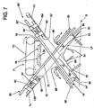
- Leading edges 90, 90' of registration platters 74, 74' and leading edges 92, 92' of clamp plates 82, 82' are beveled or otherwise machined (see FIG. 7) so as to not catch on any seams on the inside of folder pockets LP, RP , all respectively.
- insert hold-down devices such as insert hold-down solenoids 94, 94' with corresponding reciprocable retainer rods 95, 95' can be activated.
- Insert hold-down solenoids 94, 94' can be rigidly attached to anchor plates 88, 88' and when activated, insert hold-down solenoids 94, 94' actuate retainer rods 95, 95' to move downwardly to apply pressure to pocket insert materials LM, RM through clamp plate slots 96, 96' formed in clamp plates 82, 82' and registration platter slots 98, 98' formed in registration platters 74, 74' , all respectively.
- Insert hold-down solenoids 94, 94' can be located such that retainer rods 95, 95' will not contact folder pockets LP, RP but will only contact pocket insert materials LM, RM once the insert material is placed into applicable folder pockets LP or RP .
- Insert hold-down solenoids 94, 94' through retainer rods 95, 95' will hold pocket insert materials LM, RM against inside folder panels 26, 26' as they pass through clamp plate slots 96, 96' and registration platter slots 98, 98' , all respectively.
- folder F can then be advanced to Stage 2 position 70' along A-frame 52 if right folder pocket RP is to be stuffed.
- Right pocket insert material RM for right pocket RP will be advanced to Stage 2 position 70' and the above process can be repeated for stuffing right pocket RP .
- Stage 1 position 70 can then be filled with the next left pocket insert material LM and the next folder F follows just behind the one having its right pocket RP stuffed.
- insert transport surface 42 can communicate with or be extended to a downstream path represented by arrow DP directed to any structure, module, or equipment situated downstream from the folder stuffing components described herein.
- downstream path DP in connection with the use of one or more readers R as described previously enables any pocket insert material LM or RM to be selectively rejected for stuffing into a folder pocket so that it is advanced in the direction of arrow DP for diverting out of the system entirely of for further processing as desired.
- any pocket insert material LM or RM was not compiled correctly or otherwise fails a verification or integrity test, it can be rejected for stuffing and the rejected material can be transported over insert transport surface 42 and through downstream path DP for diversion of further processing.
- Such further processing can even include recovering and rerouting the rejected insert material back to the collating area for again processing it through the folder stuffing components.
- Exit swivel plate SP' comprises a central hinge 132 that allows swivel plate SP' to pivot downwardly in the center. Exit swivel plate SP' further comprises a central slot or opening 134 that allows stuffed folder SF to pass downwardly through the center. Central hinge 132 will be placed on either side of central slot 134 . Swivel plate SP' can be attached by appropriate linkage 138 to a rod-type linear actuator 136 , such as a ball screw that provides linear motion via a motor SM' .
- a rod-type linear actuator 136 such as a ball screw that provides linear motion via a motor SM' .
- a folding member or knife bar 142 of any suitable type can move downwardly into the center of stuffed folder SF , which helps keep pocket insert materials LM, RM from getting caught in fold line 24 (see FIG. 1).
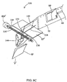
- motor SM' is activated and linear actuator 136 turns, drawing swivel plate SP' downwardly at central hinge 132 to a flat position as shown in FIG. 9B.
- knife bar 142 "breaks" fold line 24 in stuffed folder SF downward through central slot 134 until stuffed folder SF is closed and exits through swivel plate SP' .
- belt transports 144 or similar mechanism can deliver stuffed folder SF to any form of downstream processing device.
- downstream processing devices include conveyor, reading station, box, modular stuffer, poly wrapper, or any other form of processing unit.
Abstract
Description
- The present invention relates generally to stuffing folders. More particularly, the present invention relates to an apparatus and method for automatically stuffing folder pockets.
- A variety of machines and methods exist for the stuffing of envelopes or other closed-end products. U.S. Patent No. 4,055,932 to Wanner discloses an envelope stuffing machine adapted to insert sheets of paper or the like between the sides of a cover which can be drawn apart by suction to accommodate the sheets. The device further comprises a pair of opposite perforated surfaces connected to a suction chamber and between which the envelope is introduced so as to draw the opposite sides of the envelope apart to receive the sheets to be inserted.
- Additionally, U.S. Patent No. 3,999,701 to Ward; U.S. Patent No. 5,107,656 to Katz et al.; and U.S. Patent No. 5,475,968 to Linder all discuss devices for the insertion of sheets into an envelope-type packet. Ward discusses a currency-holding packet and a method of forming the packet and inserting bills of currency into the packet using prior art envelope stuffers. Katz et al. discloses a system for producing a mass distributable packet wherein a web of paper is provided and cut to form sheets. The sheets are then accumulated and stacked in a hopper and the bottom sets are successively removed and packaged in a standard envelope inserter. Linder describes a device to insert printed products into an envelope using a rotating conveying member that is equipped with receiving pockets that are distributed over its circumference and can be closed and opened.
- Finally, U.S. Patent No. 4,295,643 to de la Vega; U.S. Patent No. 5,823,320 to Seidel et al.; and U.S. Patent No. 6,311,968 to Linder et al. all disclose devices for the transporting and inserting of flat products. Each of the references is directed to devices which may be used for the transportation of newspaper jackets and insertion of various supplemental materials therein.
- As shown in the prior art, the use of machines for the stuffing of envelopes or other closed-end products is well known in the industry. However, these particular designs have not addressed the insertion of sheet articles into one or more folder pockets. Stuffing of folder pockets in the past has involved manually registering accumulated inserts, placing them in folder pockets, and folding the folder manually to produce the final product of a stuffed folder. The stuffed folder is then typically placed onto either a stack or conveyor where it is often re-checked for quality control purposes. Because this is a manual procedure, it is time consuming and subject to integrity errors, such as missing an insert or mixing the order. In addition, because of the number of repetitive motions involved, hand-stuffing folders can cause health problems.
- In light of the above, there exists a need therefore for an automated folder stuffing apparatus and method that overcomes the above described shortcomings.
- An automated folder stuffing apparatus and method is provided for stuffing a folder of the type that is foldable along a fold line and includes an inside surface and at least one pocket formed on the inside surface. The folder stuffing apparatus includes a conveyor for advancing a folder along a conveying surface of the conveyor, an opener for at least partially opening a pocket of the folder, and an inserter for inserting insert material into the folder pocket while the pocket is open. The conveyor surface can further include a plurality of vacuum ports and the conveyor can further include a rotatable endless member and a pusher element for engaging and advancing the folder along the conveyor surface. The inserter can further include an insert carriage member slidable along an insert track for releasably engaging the insert material and directing the insert material into the opened pocket. Readers can be included and utilized at various positions for reading data code, which can be on the insert material and even the folders, and the data read can be used to process items in a predetermined manner.
- A method for stuffing insert material into a pocket of a folder includes advancing a folder along a conveyor surface while an outside surface of the folder slidably contacts the conveyor surface and a pocket of the folder faces outwardly in relation to the conveyor surface. The method further includes at least partially opening the folder pocket with an opener when the folder has reached an insertion site of the conveyor surface and inserting insert material into the folder pocket while the folder is at the insertion point. The insert material and even the folders can include data codes thereon which can be used for controlling various steps of processing as desired to ensure the integrity of assembled stuffed folders.
- It is therefore an object to provide a novel automated folder stuffing apparatus and method for stuffing a folder having at least one pocket.
- An object having been stated hereinabove, and which is achieved in whole or in part by the folder stuffing apparatus and method described herein, other objects will become evident as the description proceeds when taken in connection with the accompanying drawings as best described hereinbelow.
- Exemplary embodiments of the invention will now be explained with reference to the accompanying drawings, of which:
- Figure 1 is a perspective view of a folder with two pockets stuffed with insert material;
- Figure 2 is a flow diagram illustrating an embodiment of the folder stuffing method;
- Figure 3 is a partial isometric view of a feeding and conveying system for feeding insert material into the folder stuffing apparatus;
- Figures 4A and 4B are isolated schematic isometric views of a folder feeding section of the folder stuffing apparatus;
- Figure 5 is a partial schematic view of an embodiment of the folder stuffing apparatus;
- Figure 6 is a partial isometric view of a folder stuffing stage;
- Figure 7 is a front-end view of an embodiment of the folder stuffing apparatus;
- Figure 8 is a side view of a clamping unit that can be used with the folder stuffing apparatus; and
- Figure 9A - 9C are isolated schematic isometric views illustrating use of a folder folding section of the folder stuffing apparatus.
-
- Referring now to FIG. 1, a sample folder F that can be stuffed by the apparatus and method described herein is shown. Folder F includes an outside surface generally designated 20, an inside surface generally designated 22, and a
fold line 24 that runs down the middle of folder F, preferably separating both sides equally. The left side of folder F has a left insidepanel 26 and aleft flap 28, wherein the void defined between left insidepanel 26 andleft flap 28 is the left pocket generally designated LP. Similarly, the right side of folder F has a right inside panel 26' and a right flap 28', wherein the void defined between right inside panel 26' and right flap 28' is the right pocket, generally designated RP. Collated insert material, such as, for example, left pocket insert material generally designated LM, and right pocket insert material generally designated RM, can be inserted into the appropriate pockets LP, RP of folder F as described further below. Folder F can be considered to be in a folded state when an angle A between left and right insidepanels 26, 26' is less than 180 degrees, and can be considered to be in an open state when angle A is greater than 180 degrees. - Referring now to FIG. 2, an overview of a preferred embodiment of the automated folder stuffing method is illustrated. A folder, such as folder F, of any suitable type with one or more pockets LP, RP can be automatically stuffed with accumulated pocket insert materials LM, RM, folded, and conveyed to a final destination for distribution. Stuffing can occur downstream of a device that is capable of transporting pre-collated material, typically collated by other mechanical means, such as by using push pins located along a transport surface. Primary product material, such as sheets, pamphlets, booklets, etc., can be received generally along a material feed or flow direction from an upstream location into the folder stuffing apparatus. In a preferred embodiment, primary product material can be collated into left pocket insert material LM and right pocket insert material RM. Left pocket insert material LM and right pocket insert material RM can each constitute a different predetermined combination of primary product material (e.g., one or more individual sheets, a stapled set of sheets, cards, booklets, etc.) as desired by the user for stuffing left folder pocket LP or right folder pocket RP. Left pocket insert material LM and right pocket insert material RM can be conveyed in a manner in which they will alternate along the transport surface when moving towards the folder stuffing apparatus, such that left pocket insert material LM to be stuffed in left folder pocket LP will be followed by right pocket insert material RM to be stuffed in right folder pocket RP, and this series can repeat for sets 3 and 4, 5 and 6, etc. It is also envisioned that if a user desires to stuff only one pocket of folder F, such as, for example, right folder pocket RP, only right pocket insert material RM will be produced in a series for stuffing the right folder pocket RP.
- Folder F to be stuffed can enter the folder stuffing apparatus by way of a separate conveyor that advances folder F along a conveying surface wherein folder F is in an open state. While running in parallel to the folder conveying system, left pocket insert material LM can enter a
Stage 1 position where it can be mechanically stuffed into left folder pocket LP by a process to be described in more detail below. Right pocket insert material RM can pass through theStage 1 position and enter aStage 2 position where can be mechanically stuffed in a similar manner into right folder pocket RP. After folder pockets LP, RP are automatically stuffed with pocket insert materials LM, RM, respectively, and folder F is folded, the final product, a stuffed folder, can then be transferred to a downstream location generally along an exit or output direction. - Referring to FIG. 3 where the detailed illustration of stuffing folders begins, production of a stuffed folder begins with the delivery of assembled insert material, such as from a stack or an advanced stream, from any conventional device for assembling or processing such documents. Non-limiting examples of such devices include devices or systems including feeders, cutters, readers, folders, stagers, and/or turnover devices. As illustrated in FIG. 3 in an exemplary embodiment, primary product material PM can comprise any documents suitable for assembly into a set of insert material and for stuffing into a folder as described above. As illustrated for exemplary purposes, primary product material PM comprises individual stacks of insert materials which can be fed from the side (preferably bound edge first and printed side face up for booklets, stapled sets of sheets, etc.) onto
insert transport surface 42 to form assembled sets of materials, which can be left pocket insert material LM and right pocket insert material RM. - As can be appreciated by those of skill in the art, one or more pieces of primary product material PM can include data code DC thereon, shown in FIG. 3 as bar codes. Data code DC can be positioned in any suitable location on primary product material PM and can include any suitable readable data for feeding or processing instructions or for matching with one or more folder F. Readers R can be used to read data code DC from primary product material PM at any point during processing, such as prior to advancement onto
insert transport surface 42, while being advanced ontoinsert transport surface 42, or at any desirable stage of processing after advancement ontoinsert transport surface 42. For exemplary purposes only, reading is illustrated in FIG. 3 as occurring as primary product material PM is being advanced ontoinsert transport surface 42. Readers R communicate with a central or local microprocessor M for processing of read data code DC and for controlling the processing of primary product material PM. The read data from data code DC can be used for selectively feeding certain primary product material PM in a predetermined manner and facilitating accurate matching and stuffing of primary product material PM with folders such as folder F and for verifying the integrity of stuffed folders, as further described hereinbelow. - In a preferred embodiment of stuffing a two pocket folder F with a left folder pocket LP and a right folder pocket RP, left pocket insert material LM and right pocket insert material RM can be assembled in a staggered, alternating order one behind the other. The controlled in-feed of primary product material PM to form pocket insert materials LM, RM can be implemented by providing means for feeding primary product material PM in accordance with a repeatable (i.e., cyclical) profile. It is envisioned that this profile can be programmed to enable primary product material PM to be fed in a manner creating left pocket insert material LM and right pocket insert material RM or can be programmed to only enable primary product material PM to be fed in a manner creating one set of either left pocket insert material LM or right pocket insert material RM (such as, for example, if only the right pocket RP of folder F is to be stuffed). This profile can be suitably adjusted according to user specifications. Left pocket insert material LM and right pocket insert material RM can be accumulated and formed in alternate sets along insert
transport surface 42 as they are directed toward the folder stuffing module. - It is preferable that all product material PM, whether individual sheets or multiple-sheet items such as stapled sheet sets or booklets, be fed onto
insert transport surface 42 face up and in a left-to-right orientation. In the case of bound insert materials such as booklets and pamphlets, the left-to-right orientation means that product material PM is fed with its bound edge first, which is the orientation with which conventional inserter machines feed insert materials. As a result, the insert materials constituting each left pocket insert material LM and each right pocket insert material RM are all oriented in the same manner. As described hereinbelow, each left pocket insert material LM can be inserted into left folder pocket LP of folder F such that the bound edge enters left folder pocket LP first and the non-bound edge last. By contrast, each right pocket insert material RM can be inserted into right folder pocket RP of folder F such that the non-bound edge enters right folder pocket RP first and the bound edge last. As a result, both left pocket insert material LM and right pocket insert material RM are presented in folder F in the left-to-right orientation, thereby rendering left and right pocket insert materials LM and RM immediately and easily readable upon opening the stuffed folder F. - Assembled pocket insert materials LM, RM can be pushed along
insert transport surface 42 bypush pins 44 or any other suitable form of conveying system known to those skilled in the art.Insert transport surface 42 can be further indexed with the use ofregistration straps 46 to ensure rear registration against push pins 44 as primary product material PM is fed and formed into pocket insert materials LM, RM. Registration straps 46 can be constructed of metal, cloth, plastic or any other suitable material known to those skilled in the art. After all requisite primary product material PM has been fed and pocket insert materials LM, RM have been completely formed, pocket insert materials LM, RM can be pushed downstream for further processing. - Referring now to FIGS. 4A and 4B, seriatim preparation of folders F is illustrated. Initially, folders F can be fed into a folder entry area generally designated 50 in an open position from any suitable direction. As illustrated for exemplary purposes, folders F can be provided from a direction that can be perpendicular or parallel to insert transport surface 42 (shown in Fig. 5) in order to ultimately be positioned on a folder conveyor assembly generally designated CA. As described above with reference to primary product material PM, folders F can include data code DC thereon, illustrated as bar code, which can include any suitable data for feeding or processing instructions or for matching folders F with certain, predetermined primary product material PM, such as for example assembled left pocket insert material LM and right pocket insert material RM. One or more readers R can be used to read data code DC from folders F at
folder entry area 50. Readers R can communicate with a central or local microprocessor M for processing of read data code DC and for controlling the processing of folders F. The data from each data code DC can be utilized in any suitable manner to identify and recognize folders F and to process them in a predetermined and controlled fashion. Desired folders F can be matched up with desired primary product material PM, such as left pocket insert material LM and/or right pocket insert material RM. Accurate stuffing and verification of the integrity of folders F can thus be accomplished. The processing of read data code from both folders F and primary product material PM enables automated stuffing of folders F wherein selected, predetermined folders F can be stuffed on demand and in a personalized manner with only selected, predetermined primary product material PM. Data code DC on primary pocket material PM and folders F can further be processed and used to determine what to do to certain folders F. For example, instructions can be provided to selectively print or paint certain items on selected folders F, or instructions can be provided as to whether or not to stuff certain folders F at all as advanced pocket insert material and/or folders F can be selectively advanced without being stuffed as described further below with reference to FIG. 5. - In a preferred embodiment, folder conveyor assembly CA is configured as an
A-frame structure 52 having a first conveyor surface generally designated 52A and a second conveyor surface generally designated 52B wherein first and second conveyor surfaces 52A, 52B are joined at acommon edge 53 and extend outwardly at an angle fromcommon edge 53 relative to a base plane generally designated B. Conveyor assembly CA further comprises a conveyor consisting of, for example, anendless member 61 such as a chain or belt withpusher elements 62 such as grips or fingers, or any other conveying mechanism known to those skilled in the art. - In a preferred embodiment, folder F can enter
folder entry area 50 and come to rest in a substantially flat position on a swivel plate SP, as shown in FIGS. 4A and 4B. Swivel plate SP is an invertible section comprising acentral hinge 54 that allows swivel plate SP to pivot upwardly in the center. Swivel plate SP is further attached byappropriate linkages 55 to a rod-typelinear actuator 56, such as a ball screw that provides linear motion via a motor SM. Swivel plate SP can also comprise one ormore vacuum ports 58 through which a vacuum can be applied as can be appreciated by those of skill in the art to suitably hold folder F to swivel plate SP during the upward motion of swivel plate SP. - Once folder F has entered
folder entry area 50 and has come to rest on swivel plate SP, a vacuum is applied throughvacuum ports 58 to secure folder F. Motor SM is then activated, thus turninglinear actuator 56drawing linkages 55 on both ends of swivel plate SP towards one another, thus urging swivel plate SP upwardly atcentral hinge 54, as shown in FIG. 4B. Folder F, maintained in position on swivel plate SP, will also be drawn upwardly atfolder fold line 24 thus drawing folder F from a substantially flat position to an inverted position with folder insidesurface 22 facing outwardly and left and right folder insidepanels 26, 26' substantially coplanar with first and second conveyor surfaces 52A, 52B. - Once opened and suitably partially inverted, folder F can be conveyed onto
A-frame 52 and moved downstream towards aStage 1 position 70 (shown in FIG. 5) viaendless member 61 andpusher elements 62. Folder F can be advanced alongA-frame 52 for further processing while folder F maintains an inverted state wherein folder insidesurface 22 and folder left and right pockets LP, RP face outwardly in relation to first and second conveyor surfaces 52A, 52B. - Referring now to FIGS. 5 - 7, folder stuffing stages of a preferred embodiment of
folder stuffing apparatus 10 are described. Two folder stuffing stages include aStage 1position 70, where left folder pocket LP can be stuffed and aStage 2 position 70', where right folder pocket RP can be stuffed. As shown in FIG. 5, left pocket insert material LM and right pocket insert material RM that are to be stuffed into left folder pocket LP and right folder pocket RP, respectively, can be located above folder F that is carried alongA-frame 52. - Insert material for entering folder stuffing stages 70, 70' can be read or otherwise recognized as consisting of left pocket insert material LM or right pocket insert material RM. If the insert material is left pocket insert material LM, it will be processed in
Stage 1position area 70 for stuffing into left folder pocket LP; similarly, if the insert material is right pocket insert material RM, it will pass throughStage 1position 70 and move further downstream to be processed inStage 2 position area 70' for stuffing into right folder pocket RP. As discussed earlier, if a user desires that only one pocket of a two pocket folder F be filled (or if the user is stuffing a one pocket folder F), the stage position that is not being used to fill a folder pocket can be intentionally by-passed. For example, if a user desires to fill only right folder pocket RP of a two pocket folder F,Stage 1position 70 that normally stuffs left folder pocket LP can be by-passed such thatStage 2 position 70' to fill right folder pocket RP will only be activated and vice-versa. Each of the two folder stuffing stages 70, 70' described above can operate in a similar manner as will now be described in further detail below. - When the particular pocket insert materials LM, RM enter the appropriate folder stuffing stage (i.e.,
Stage 1position 70 for left pocket insert material LM andStage 2 position 70' for right pocket insert material RM), side transporters generally designated ST, ST' can be activated. In a preferred embodiment, side transporters ST, ST', respectively, compriseendless belt systems 72, 72' with push pins 78, 78' or any other suitable conveying system as known to those skilled in the art and can be oriented transversely to inserttransport surface 42. Side transporters ST, ST' can activate to transfer applicable pocket insert materials LM, RM frominsert transport surface 42 to insert carriage members generally designated 80, 80'. -
Insert carriage members 80, 80' can be slidably attached to insert track orguide rails 76, 76' such thatinsert carriage members 80, 80' and all associated mechanisms can move up and downguide rails 76, 76' as necessary, driven by motors M, M' (see FIG. 6). As shown in FIGS. 6 and 7, in a preferred embodiment,guide rails 76, 76' are configured so thatinsert carriage members 80, 80' are slidable alongguide rails 76, 76' through an insert path that is substantially coplanar with first and second conveyor surfaces 52A, 52B, respectively. -
Insert carriage member 80, used inStage 1position 70, is shown in FIGS. 7 and 8, with an isolated view illustrated in FIG. 8. Insert carriage member 80' (shown in FIGS. 6 and 7) used inStage 2 position 70' can be similarly configured.Insert carriage members 80, 80' can compriseclamp plates 82, 82' that are attached toregistration platters 74, 74' byclamp plate solenoids 84, 84'.Clamp plate solenoids 84, 84' allowclamp plates 82, 82' to be raised and lowered onto pocket insert materials LM, RM, thus catching pocket insert materials LM, RM in a secured manner betweenclamp plates 82, 82' andregistration platters 74, 74', respectively.Registration platters 74, 74',clamp plates 82, 82', and clampplate solenoids 84, 84', respectively, together form theinsert carriage members 80, 80' which hold pocket insert materials LM, RM, respectively, and subsequently place pocket insert materials LM, RM into the applicable folder pockets LP, RP, respectively. It thus can be seen thatinsert carriage members 80, 80' can operate as staging devices to hold pocket insert materials LM, RM as necessary for a predetermined or programmed period of time. The ability to stage pocket insert materials LM, RM in this manner facilitates the synchronization of the operation ofinsert carriage members 80, 80' with other operative components offolder stuffing apparatus 10, such as pocketopening vacuum solenoids 86, 86' described hereinbelow. - As shown in FIG. 7, push pins 78, 78' that are attached to the drive belts of
endless belt systems 72, 72' can contact the applicable pocket insert materials LM, RM and transfer them in a transverse direction off ofinsert transport surface 42 and ontoregistration platters 74, 74' ofinsert carriage members 80, 80'. Push pins 78, 78' will push pocket insert materials LM, RM to a predetermined position onregistration platters 74, 74' and will then stop movement, thus holding pocket insert materials LM, RM in position. Push pins 78, 78' can produce a jogging movement to register pocket insert materials LM, RM such that their contents are rear end and edge registered for placement into the applicable pockets LP, RP of folder F. - Referring back to FIGS. 5-7, once push pins 78, 78' have moved pocket insert material LM, RM into position and have edge registered the inserts by jogging,
clamp plates 82, 82' can be lowered on pocket insert material LM, RM, thus securing pocket insert material LM, RM betweenclamp plates 82, 82' andregistration platters 74, 74' ofinsert carriage members 80, 80' for subsequent placement into applicable folder pockets LP, RP, respectively, guided byinsert carriage members 80, 80', respectively. - With pocket insert materials LM, RM secured to insert
carriage members 80, 80', respectively, and waiting or staged for insertion byinsert carriage members 80, 80', respectively, folder F is pushed alongA-frame 52 into position for stuffing, withgripper finger pushers 62 pushing folder F from the rear or by another suitable conveying system. Additional holding support on first and second conveyor surfaces 52A, 52B for folder F can be provided by suitable vacuum throughvacuum ports 64 or similar mechanisms embedded inA-frame 52 that subjects outsidesurface 20 of folder F to a vacuum, thus securing folder F toA-frame 52. - Once folder F is in position between
guide rails 76, 76', pocket openers such as pocketopening vacuum solenoids 86, 86' as illustrated in FIG. 6, or other suitable opening mechanisms, can be used to open left folder pocket LP or right folder pocket RP, as applicable (FIG. 6 illustrates the process inStage 2 position 70' of stuffing right folder pocket RP). Pocketopening vacuum solenoids 86, 86' can be rigidly attached to anchorplates 88, 88' that are rigidly attached to the apparatus frame (not shown). As shown in FIG. 7, pocketopening vacuum solenoids 86, 86' are lowered onto and engagefolder flaps 28, 28', respectively. WithA-frame vacuum ports 64 providing suction on folder outside surface 20 (shown in FIG. 1), pocketopening vacuum solenoids 86, 86' are raised back towards their initial positions, thus raising folder flaps 28, 28' and opening folder pockets LP, RP. - With folder pockets LP, RP in an open position, pocket insert materials LM, RM (as applicable) secured by
insert carriage members 80, 80' (includingregistration platters 74, 74',clamp plates 82, 82', and clampplate solenoids 84, 84') can then move downwardly onguide rails 76, 76' by motors M, M' to move pocket insert materials LM, RM into folder pockets LP, RP, all respectively. The leading edges of pocket insert materials LM, RM are protected on top byclamp plates 82, 82' and on the bottom byregistration platters 74, 74' so that pocket insert materials LM, RM will not catch on any seams onflaps 28, 28' orinside panels 26, 26' on the inside of folder pockets LP, RP. Leadingedges 90, 90' ofregistration platters 74, 74' andleading edges 92, 92' ofclamp plates 82, 82' are beveled or otherwise machined (see FIG. 7) so as to not catch on any seams on the inside of folder pockets LP, RP, all respectively. - Referring to FIGS. 6 and 7, once
insert carriage members 80, 80' with pocket insert materials LM, RM have come to a position fully inside folder pockets LP, RP, insert hold-down devices, such as insert hold-downsolenoids 94, 94' with correspondingreciprocable retainer rods 95, 95' can be activated. Insert hold-downsolenoids 94, 94' can be rigidly attached to anchorplates 88, 88' and when activated, insert hold-downsolenoids 94, 94' actuateretainer rods 95, 95' to move downwardly to apply pressure to pocket insert materials LM, RM throughclamp plate slots 96, 96' formed inclamp plates 82, 82' andregistration platter slots 98, 98' formed inregistration platters 74, 74', all respectively. Insert hold-downsolenoids 94, 94' can be located such thatretainer rods 95, 95' will not contact folder pockets LP, RP but will only contact pocket insert materials LM, RM once the insert material is placed into applicable folder pockets LP or RP. Insert hold-downsolenoids 94, 94' throughretainer rods 95, 95' will hold pocket insert materials LM, RM againstinside folder panels 26, 26' as they pass throughclamp plate slots 96, 96' andregistration platter slots 98, 98', all respectively. - With insert hold-down
solenoid retainer rods 95, 95' applying pressure to pocket insert materials LM, RM,clamp plate solenoids 84, 84' will raiseclamp plates 82, 82', thus retractingclamp plates 82, 82' off of pocket insert materials LM, RM, respectively, and back to their initial positions.Insert carriage members 80, 80' will then retract upwardly alongguide rails 76, 76' through motors M, M', respectively. Insert hold-downsolenoid retainer rods 95, 95' and pocket openingsolenoids 86, 86', respectively, will then retract to their initial positions, and the folder stuffing cycle is complete. - As can be appreciated, if the folder stuffing cycle described above occurred in
Stage 1 position 70 (stuffing of left folder pocket LP), folder F can then be advanced to Stage 2 position 70' alongA-frame 52 if right folder pocket RP is to be stuffed. Right pocket insert material RM for right pocket RP will be advanced toStage 2 position 70' and the above process can be repeated for stuffing right pocket RP. Concurrently,Stage 1position 70 can then be filled with the next left pocket insert material LM and the next folder F follows just behind the one having its right pocket RP stuffed. - Referring again to FIG. 5, insert
transport surface 42 can communicate with or be extended to a downstream path represented by arrow DP directed to any structure, module, or equipment situated downstream from the folder stuffing components described herein. The realization of downstream path DP in connection with the use of one or more readers R as described previously enables any pocket insert material LM or RM to be selectively rejected for stuffing into a folder pocket so that it is advanced in the direction of arrow DP for diverting out of the system entirely of for further processing as desired. For example, if any pocket insert material LM or RM was not compiled correctly or otherwise fails a verification or integrity test, it can be rejected for stuffing and the rejected material can be transported overinsert transport surface 42 and through downstream path DP for diversion of further processing. Such further processing can even include recovering and rerouting the rejected insert material back to the collating area for again processing it through the folder stuffing components. - Referring now to FIGS. 9A - 9C, in a preferred embodiment, once folder F is stuffed with applicable pocket insert materials LM, RM, the completed stuffed folder SF can be advanced into a folder folding section generally designated 130 and onto an exit swivel plate SP' (shown in an up position in FIG. 9A). Exit swivel plate SP' comprises a
central hinge 132 that allows swivel plate SP' to pivot downwardly in the center. Exit swivel plate SP' further comprises a central slot or opening 134 that allows stuffed folder SF to pass downwardly through the center.Central hinge 132 will be placed on either side ofcentral slot 134. Swivel plate SP' can be attached byappropriate linkage 138 to a rod-typelinear actuator 136, such as a ball screw that provides linear motion via a motor SM'. - Referring to FIG. 9A, once stuffed folder SF is advanced onto swivel plate SP', a folding member or
knife bar 142 of any suitable type can move downwardly into the center of stuffed folder SF, which helps keep pocket insert materials LM, RM from getting caught in fold line 24 (see FIG. 1). Onceknife bar 142 comes into contact with stuffed folder SF, motor SM' is activated andlinear actuator 136 turns, drawing swivel plate SP' downwardly atcentral hinge 132 to a flat position as shown in FIG. 9B. As illustrated in FIG. 9C,knife bar 142 "breaks"fold line 24 in stuffed folder SF downward throughcentral slot 134 until stuffed folder SF is closed and exits through swivel plate SP'. - Once stuffed folder SF exits the system, belt transports 144 or similar mechanism can deliver stuffed folder SF to any form of downstream processing device. Non-limiting examples of downstream processing devices include conveyor, reading station, box, modular stuffer, poly wrapper, or any other form of processing unit.
- It will be understood that various details of the invention may be changed without departing from the scope of the invention. Furthermore, the foregoing description is for the purpose of illustration only, and not for the purpose of limitation―the invention being defined by the claims.
Claims (42)
- An automated folder stuffing apparatus for stuffing a folder foldable along a fold line and including an inside surface and at least one pocket formed on the inside surface, the folding stuffer apparatus comprising:(a) a conveyor for advancing a folder along a conveyor surface;(b) an opener for at least partially opening a pocket of the folder; and(c) an inserter for inserting insert material into the folder pocket while the pocket is open.
- The folder stuffing apparatus according to claim 1 wherein the at least one pocket comprises a flap and wherein the opener further opens the flap.
- The folder stuffing apparatus according to claim 1 wherein the conveyor surface comprises a plurality of vacuum ports for subjecting an outside surface of the folder to a vacuum.
- The folder stuffing apparatus according to claim 1 wherein the conveyor comprises a rotatable endless member and a pusher element connected to the endless member and movable therewith for engaging and advancing the folder along the conveyor surface.
- The folder stuffing apparatus according to claim 1 wherein the opener comprises a vacuum cup mounted above the conveyor surface and actuatable into contact with the pocket.
- The folder stuffing apparatus according to claim 1 wherein the inserter comprises an insert carriage member slidable along an insert track for releasably engaging the insert material and directing the insert material into the opened pocket.
- The folder stuffing apparatus according to claim 6 further comprising an insert hold-down device actuatable into engagement with the insert material while the insert material is in the pocket for retaining the insert material while the insert carriage member releases the insert material.
- The folder stuffing apparatus according to claim 6 further comprising an insert transport surface disposed above the conveyor surface for transporting the insert material to the insert carriage member.
- The folder stuffing apparatus according to claim 8 further comprising a side transporter for transferring the insert material from the insert transport surface to the insert carriage member.
- An automated folder stuffing apparatus for stuffing a folder of a type comprising an outside surface, first and second inside panels joined at a fold line and foldable toward each other at the fold line, and a pocket formed on one of the inside panels, the apparatus comprising:(a) a conveyor surface comprising first and second conveyor surface portions joined at a common edge and extending outwardly at an angle from the common edge;(b) a conveyor movable in relation to the conveyor surface for advancing the folder along the conveyor surface and maintaining the folder in an open state wherein the outside surface slidably contacts the first and second conveyor surface portions and the pocket faces outwardly in relation to at least one of the first and second conveyor surface portions;(c) an opener for at least partially opening the pocket while the folder is on the conveyor surface; and(d) an inserter for inserting insert material into the pocket while the pocket is open.
- The folder stuffing apparatus according to claim 10 wherein the first and second conveyor surface portions comprise a plurality of vacuum ports for subjecting the outside surface of the folder to a vacuum.
- The folder stuffing apparatus according to claim 10 wherein the conveyor comprises a rotatable endless member and a pusher element connected to the endless member and movable therewith for engaging and advancing the folder along the conveyor surface.
- The folder stuffing apparatus according to claim 10 wherein the opener comprises a vacuum cup mounted above the conveyor surface and actuatable into contact with the pocket.
- The folder stuffing apparatus according to claim 10 wherein the inserter comprises an insert carriage member slidable along an insert track for releasably engaging the insert material and directing the insert material into the opened pocket.
- The folder stuffing apparatus according to claim 14 wherein each of the first and second conveyor surface portions is oriented at an angle relative to a base plane and wherein the insert carriage member is slidable along the insert track through an insert path coplanar with one of the conveyor surface portions.
- The folder stuffing apparatus according to claim 14 comprising an insert hold-down device actuatable into engagement with the insert material while the insert material is in the pocket for retaining the insert material while the insert carriage member releases the insert material.
- The folder stuffing apparatus according to claim 14 comprising an insert transport surface disposed above the conveyor surface for transporting the insert material to the insert carriage member.
- The folder stuffing apparatus according to claim 17 comprising a side transporter for transferring the insert material from the insert transport surface to the insert carriage member.
- An automated folder stuffing apparatus for stuffing a folder of a type comprising first and second inside panels foldable toward each other along a fold line, and first and second inside pockets respectively formed on the first and second inside panels, the folder stuffing apparatus comprising:(a) a conveyor assembly comprising a conveyor surface disposed along a central longitudinal axis and a conveyor for advancing the folder along the conveyor surface while maintaining the folder in an open state at which the first and second pockets face outwardly in relation to the conveyor surface, the first pocket being disposed on a first side of the longitudinal axis, and the second pocket being disposed on a second side of the longitudinal axis;(b) first and second openers mounted above the conveyor surface for respectively opening the first and second pockets;(c) a first inserter for inserting a first insert material into the first pocket and comprising a first insertion track and a first carriage member slidable along the first insertion track from the second side of the longitudinal axis to the first side of the longitudinal axis; and(d) a second inserter for inserting a second insert material into the second pocket and comprising a second insertion track and a second carriage member slidable along the second insertion track from the first side of the longitudinal axis to the second side of the longitudinal axis.
- The folder stuffing apparatus according to claim 19 comprising an insert transport surface disposed above the conveyor surface and a side transporter for transferring the first and second insert materials from the insert transport surface to the first and second insertion devices, respectively.
- A method for stuffing insert material into a pocket of a folder, the method comprising the steps of:(a) advancing a folder along a conveyor surface while an outside surface of the folder slidably contacts the conveyor surface and a pocket of the folder faces outwardly in relation to the conveyor surface;(b) at least partially opening the folder pocket when the folder has reached an insertion site of the conveyor surface; and(c) inserting insert material into the folder pocket while the folder is at the insertion site.
- The method according to claim 21 further comprising the step of collating a set of insert elements to form the insert material to be inserted into the pocket.
- The method according to claim 21 further comprising the steps of advancing the insert material along an insert transport surface disposed above the conveyor surface, and transporting the insert material off the insert transport surface to an insert carriage member, wherein the step of inserting the insert material comprises conveying the insert material from the insert carriage member to the opened pocket below the insert transport surface.
- The method according to claim 23 wherein the folder includes first and second inside panels foldable toward each other along a fold line and the pocket is formed on one of the first or second inside panels, wherein an angled portion of the conveyor surface is disposed at an acute angle in relation to a base plane, the inside panel on which the pocket is formed is at least substantially coplanar with the angled portion, and the insert material is conveyed by the insert carriage member along an insert path generally coplanar with the angled portion and the inside panel on which the pocket is formed.
- The method according to claim 23 comprising the step of staging the insert material within the insert carriage member after transporting the insert material off the insert transport surface, wherein the staging transpires for a period of time prior to inserting the insert material into the opened pocket.
- The method according to claim 25 wherein the insert material is staged at an elevation greater than an elevation of the insert transport surface.
- The method according to claim 23 comprising releasing the insert material after conveying the insert material to the opened pocket.
- The method according to claim 21 wherein the folder includes first and second inside panels foldable toward each other along a fold line and the pocket is formed on one of the first or second inside panels.
- The method according to claim 28 wherein an angle between the first and second inside panels is approximately 180 degrees or greater while the folder is advancing along the conveyor surface.
- The method according to claim 28 wherein the conveyor surface comprises an inverted section extending upwardly at an acute angle in relation to a base plane, and, while the folder is being advanced, the inside panel on which the pocket is formed is coplanar with the inverted section.
- The method according to claim 30 wherein the conveyor surface comprises an invertible section situated adjacent to and upstream from the inverted section, and the step of advancing the folder comprises:(a) providing the folder on the invertible section of the conveyor surface while the folder is in a flat state at which an angle between the first and second inside panels is approximately 180 degrees;(b) pivoting the invertible section to the acute angle to align the inside panel on which the pocket is formed in coplanar relation to the inverted section; and(c) advancing the folder from the pivoted invertible section to the inverted section.
- The method according to claim 28 further comprising the steps of advancing the folder stuffed with the insert material to a folding site situated downstream from the insertion site and, at the folding site, folding the folder such that an angle between the first and second inside panels is less than 180 degrees.
- The method according to claim 32 wherein the folding step comprises forcibly contacting the folder at its fold line to move the folder through an opening of a surface of the folding site.
- The method according to claim 21 comprising the step of determining whether the insert material is to be rejected and, if the insert material is to be rejected, refraining from performing the folder pocket opening and insert material inserting steps and diverting the insert material to a downstream path situated downstream from the insertion site.
- A folding apparatus for producing a folder, the folding apparatus comprising:(a) a frame for supporting an open folder thereon, the frame defining a slot therethrough;(b) a folding member for extending at least partially through the slot;(c) whereby the folding member is operable to contact an open folder supported on the frame and extend at least partially through the slot to push the open folder along a fold line such that the folder passes through the slot in a closed position.
- The folding apparatus of claim 35 wherein the frame comprises two sides interconnected by a hinge.
- The folder stuffing apparatus of claim 1 further comprising one or more readers for reading data code.
- The method according to claim 21 further comprising reading data code from the insert material and inserting the insert material into the folder pocket based upon the data code.
- The method according to claim 38 further comprising reading folder data code from the folder and processing the folder based upon the folder data code.
- The method according to claim 21 wherein the insert material, prior to being inserted into the folder pocket, is advanced along an insert transport surface wherein the insert material is oriented in a uniform manner.
- A method for stuffing insert material into a pocket of a folder, the method comprising the steps of:(a) providing a folder;(b) providing insert material having data code thereon, the data code comprising readable instructions for processing of the insert material;(c) reading the data code from the insert material;(d) at least partially opening the folder pocket; and(e) stuffing the insert material into the folder pocket based upon a determination to do so by the data code read from the insert material.
- The method according to claim 41 wherein the folder has folder data code thereon, the folder data code comprising readable instructions for processing of the folder, and further comprising the steps of:(a) reading the folder data code from the folder; and(b) processing the folder based upon the folder data code.
Applications Claiming Priority (2)
| Application Number | Priority Date | Filing Date | Title |
|---|---|---|---|
| US34469501P | 2001-10-19 | 2001-10-19 | |
| US344695P | 2001-10-19 |
Publications (2)
| Publication Number | Publication Date |
|---|---|
| EP1304233A2 true EP1304233A2 (en) | 2003-04-23 |
| EP1304233A3 EP1304233A3 (en) | 2009-10-14 |
Family
ID=23351599
Family Applications (1)
| Application Number | Title | Priority Date | Filing Date |
|---|---|---|---|
| EP02023402A Withdrawn EP1304233A3 (en) | 2001-10-19 | 2002-10-18 | Apparatus and method for stuffing a folder |
Country Status (3)
| Country | Link |
|---|---|
| US (1) | US7000364B2 (en) |
| EP (1) | EP1304233A3 (en) |
| CA (1) | CA2408879C (en) |
Cited By (2)
| Publication number | Priority date | Publication date | Assignee | Title |
|---|---|---|---|---|
| DE202013104806U1 (en) * | 2013-10-28 | 2015-01-30 | Böwe Systec Gmbh | Device for processing goods to a mail item |
| DE102013111843A1 (en) * | 2013-10-28 | 2015-04-30 | Böwe Systec Gmbh | Method and device for processing goods to a mail item |
Families Citing this family (7)
| Publication number | Priority date | Publication date | Assignee | Title |
|---|---|---|---|---|
| US7858599B2 (en) * | 2005-12-30 | 2010-12-28 | Hander Robert W | Enhancement of urogenital function |
| AT505819B1 (en) * | 2007-09-26 | 2009-07-15 | Elag Ast Gmbh | METHOD AND DEVICE FOR PRODUCING BAGS SERVING NAPKINS |
| EP2123475B1 (en) * | 2008-05-20 | 2013-10-09 | Neopost Technologies | Apparatus and method for inserting a postal item into an envelope and moistening the flap of the envelope |
| US8695313B2 (en) * | 2008-12-04 | 2014-04-15 | Lockheed Martin Corporation | Method of inserting mail pieces into individual folder |
| US8816236B2 (en) * | 2008-12-15 | 2014-08-26 | Siemens Industry, Inc. | Mail holder for use in a mail sorting system |
| EP3015259B1 (en) * | 2010-10-26 | 2019-01-30 | Riso Kagaku Corporation | Envelope sheet |
| JP6681903B2 (en) * | 2014-12-18 | 2020-04-15 | ベター オール ラウンド リミテッド | Method and device for folding and opening wiping material |
Citations (7)
| Publication number | Priority date | Publication date | Assignee | Title |
|---|---|---|---|---|
| US3999701A (en) | 1974-05-23 | 1976-12-28 | Mail-Well Envelope Company | Currency holding folder |
| US4055932A (en) | 1975-12-20 | 1977-11-01 | Bowe Bohler & Weber Kg Maschinenfabrik | Envelope-stuffing machine |
| US4295643A (en) | 1979-06-13 | 1981-10-20 | Vega Alejandro J De | Apparatus and method for handling jackets of printed matter |
| US5107656A (en) | 1990-07-06 | 1992-04-28 | Webcraft Technologies, Inc. | Assembly for producing a mass distributable printed packet |
| US5475968A (en) | 1992-09-14 | 1995-12-19 | Grapha-Holding Ag | Device for combining printed products that are supplied to a folded envelope |
| US5823320A (en) | 1995-03-09 | 1998-10-20 | Graphic Management Associates, Inc. | Inserter for flat products |
| US6311968B1 (en) | 1997-10-27 | 2001-11-06 | Grapha-Holding Ag | Method of producing printed products by inserting partial products and/or enclosures into a primary product, and device for executing the method |
Family Cites Families (16)
| Publication number | Priority date | Publication date | Assignee | Title |
|---|---|---|---|---|
| US3934867A (en) * | 1974-06-03 | 1976-01-27 | Pitney-Bowes, Inc. | Collating, folding and inserting system |
| US3965644A (en) * | 1975-10-31 | 1976-06-29 | Bell & Howell Company | Apparatus and method for mail preparation |
| CH586611A5 (en) * | 1975-11-14 | 1977-04-15 | Grapha Holding Ag | |
| US4071997A (en) * | 1976-04-27 | 1978-02-07 | Gunther Business Systems, Inc. | Mechanism and method of making an envelope |
| US4543768A (en) * | 1981-05-30 | 1985-10-01 | Takatori Machinery Works Ltd. | Automatic method and apparatus for packing stockings or the like |
| US4712359A (en) * | 1986-10-14 | 1987-12-15 | J.A.D. Enterprises, Inc. | Mail inserting and collating apparatus |
| US4955185A (en) * | 1987-03-25 | 1990-09-11 | Bell & Howell Company | Insertion machine |
| EP0671286B1 (en) * | 1992-11-11 | 1998-10-07 | Juki Corporation | Unit for processing envelope |
| FR2701778B1 (en) * | 1993-02-17 | 1995-03-31 | Neopost Ind | Electronic page inverter for a mail processing and folder-inserter system including such an inverter. |
| US5388388A (en) * | 1993-06-11 | 1995-02-14 | Pitney Bowes Inc. | Method and apparatus for diverting an envelope in an inserter |
| US5555701A (en) * | 1994-11-29 | 1996-09-17 | Fehringer; Robert | Envelope wetting and sealing apparatus |
| US5898153A (en) * | 1995-02-01 | 1999-04-27 | Publishers Clearing House | Method for processing mail in a sweepstakes contest |
| US5560185A (en) * | 1995-04-20 | 1996-10-01 | Glenn Petkovsek | System and method for sealing a flapless envelope |
| CH690855A5 (en) * | 1996-05-07 | 2001-02-15 | Grapha Holding Ag | Apparatus for transporting printed sheets particularly in a saddle stitcher or a gathering machine. |
| US6666610B1 (en) * | 1999-03-18 | 2003-12-23 | Meadwestvaco Corporation | Folder |
| US6116652A (en) * | 1999-11-22 | 2000-09-12 | The Link To Learning Llc | Learning materials delivery system |
-
2002
- 2002-10-18 CA CA002408879A patent/CA2408879C/en not_active Expired - Fee Related
- 2002-10-18 US US10/273,464 patent/US7000364B2/en not_active Expired - Fee Related
- 2002-10-18 EP EP02023402A patent/EP1304233A3/en not_active Withdrawn
Patent Citations (7)
| Publication number | Priority date | Publication date | Assignee | Title |
|---|---|---|---|---|
| US3999701A (en) | 1974-05-23 | 1976-12-28 | Mail-Well Envelope Company | Currency holding folder |
| US4055932A (en) | 1975-12-20 | 1977-11-01 | Bowe Bohler & Weber Kg Maschinenfabrik | Envelope-stuffing machine |
| US4295643A (en) | 1979-06-13 | 1981-10-20 | Vega Alejandro J De | Apparatus and method for handling jackets of printed matter |
| US5107656A (en) | 1990-07-06 | 1992-04-28 | Webcraft Technologies, Inc. | Assembly for producing a mass distributable printed packet |
| US5475968A (en) | 1992-09-14 | 1995-12-19 | Grapha-Holding Ag | Device for combining printed products that are supplied to a folded envelope |
| US5823320A (en) | 1995-03-09 | 1998-10-20 | Graphic Management Associates, Inc. | Inserter for flat products |
| US6311968B1 (en) | 1997-10-27 | 2001-11-06 | Grapha-Holding Ag | Method of producing printed products by inserting partial products and/or enclosures into a primary product, and device for executing the method |
Cited By (3)
| Publication number | Priority date | Publication date | Assignee | Title |
|---|---|---|---|---|
| DE202013104806U1 (en) * | 2013-10-28 | 2015-01-30 | Böwe Systec Gmbh | Device for processing goods to a mail item |
| DE102013111843A1 (en) * | 2013-10-28 | 2015-04-30 | Böwe Systec Gmbh | Method and device for processing goods to a mail item |
| DE102013111843B4 (en) * | 2013-10-28 | 2015-08-06 | Böwe Systec Gmbh | Method and device for processing goods to a mail item |
Also Published As
| Publication number | Publication date |
|---|---|
| CA2408879C (en) | 2006-07-25 |
| US7000364B2 (en) | 2006-02-21 |
| CA2408879A1 (en) | 2003-04-19 |
| US20030121236A1 (en) | 2003-07-03 |
| EP1304233A3 (en) | 2009-10-14 |
Similar Documents
| Publication | Publication Date | Title |
|---|---|---|
| US5100116A (en) | Apparatus and method of processing signatures | |
| US6540223B2 (en) | On-edge stacking apparatus | |
| US5950399A (en) | Apparatus and method for inserting a product into an envelope and closing same | |
| US20060030468A1 (en) | Method of forming composite informational item | |
| EP1334937B1 (en) | Method and apparatus for assembling a stack of sheet articles from multiple input paths | |
| US6813870B2 (en) | Method and apparatus for inserting insert material into an envelope | |
| US7000364B2 (en) | Apparatus and method for stuffing a folder | |
| US5876029A (en) | Feeder assembly apparatus | |
| US5924265A (en) | Vacuum deck stopping mechanism | |
| US6915184B2 (en) | Collator | |
| DE60035942T2 (en) | Method for feeding envelopes to an inserter | |
| US6689040B2 (en) | Right angle turning device for an inserter system and corresponding method | |
| GB2283232A (en) | Folding collations having two different size documents. | |
| US6164640A (en) | Apparatus for directionally reorienting sheets | |
| EP1634840A1 (en) | Sheet accumulator systems | |
| US6793212B2 (en) | On-edge envelope stacker adjustable for different sized articles | |
| US7934357B2 (en) | Jam access system for sheet handling apparatus | |
| EP1634834A2 (en) | Speed control for sheet handling apparatus | |
| US20060151941A1 (en) | Speed control for sheet handling apparatus | |
| US20030080486A1 (en) | Inserting machine with interchangeable modules | |
| US7380790B2 (en) | Trailing edge rotating deflector with center passage for sheet handling apparatus | |
| EP2364943A2 (en) | Apparatus and process for sorting a sequential flow of postal items according to a predetermined criterion and wrapping up the postal items so sorted | |
| EP1634835B1 (en) | Trailing edge deflector for sheet handling apparatus and corresponding method | |
| US20070062163A1 (en) | Inserter | |
| JP2002284435A (en) | Enclosure forming device |
Legal Events
| Date | Code | Title | Description |
|---|---|---|---|
| PUAI | Public reference made under article 153(3) epc to a published international application that has entered the european phase |
Free format text: ORIGINAL CODE: 0009012 |
|
| AK | Designated contracting states |
Designated state(s): AT BE BG CH CY CZ DE DK EE ES FI FR GB GR IE IT LI LU MC NL PT SE SK TR |
|
| AX | Request for extension of the european patent |
Extension state: AL LT LV MK RO SI |
|
| RAP1 | Party data changed (applicant data changed or rights of an application transferred) |
Owner name: BOWE BELL + HOWELL COMPANY |
|
| PUAL | Search report despatched |
Free format text: ORIGINAL CODE: 0009013 |
|
| AK | Designated contracting states |
Kind code of ref document: A3 Designated state(s): AT BE BG CH CY CZ DE DK EE ES FI FR GB GR IE IT LI LU MC NL PT SE SK TR |
|
| AX | Request for extension of the european patent |
Extension state: AL LT LV MK RO SI |
|
| AKX | Designation fees paid | ||
| STAA | Information on the status of an ep patent application or granted ep patent |
Free format text: STATUS: THE APPLICATION IS DEEMED TO BE WITHDRAWN |
|
| 18D | Application deemed to be withdrawn |
Effective date: 20100415 |
|
| REG | Reference to a national code |
Ref country code: DE Ref legal event code: 8566 |