EP1303709B1 - A set of brakes and a vehicle with said set of wet brakes - Google Patents
A set of brakes and a vehicle with said set of wet brakes Download PDFInfo
- Publication number
- EP1303709B1 EP1303709B1 EP01950125A EP01950125A EP1303709B1 EP 1303709 B1 EP1303709 B1 EP 1303709B1 EP 01950125 A EP01950125 A EP 01950125A EP 01950125 A EP01950125 A EP 01950125A EP 1303709 B1 EP1303709 B1 EP 1303709B1
- Authority
- EP
- European Patent Office
- Prior art keywords
- brake
- brakes
- disks
- disk
- housing
- Prior art date
- Legal status (The legal status is an assumption and is not a legal conclusion. Google has not performed a legal analysis and makes no representation as to the accuracy of the status listed.)
- Expired - Lifetime
Links
- 230000000694 effects Effects 0.000 claims abstract description 18
- 238000004519 manufacturing process Methods 0.000 description 7
- 239000000463 material Substances 0.000 description 5
- 238000005266 casting Methods 0.000 description 2
- 238000010276 construction Methods 0.000 description 2
- 239000000945 filler Substances 0.000 description 2
- 238000003754 machining Methods 0.000 description 2
- 230000004075 alteration Effects 0.000 description 1
- 238000001816 cooling Methods 0.000 description 1
- 238000012986 modification Methods 0.000 description 1
- 230000004048 modification Effects 0.000 description 1
- 238000007789 sealing Methods 0.000 description 1
Images

Classifications
-
- F—MECHANICAL ENGINEERING; LIGHTING; HEATING; WEAPONS; BLASTING
- F16—ENGINEERING ELEMENTS AND UNITS; GENERAL MEASURES FOR PRODUCING AND MAINTAINING EFFECTIVE FUNCTIONING OF MACHINES OR INSTALLATIONS; THERMAL INSULATION IN GENERAL
- F16D—COUPLINGS FOR TRANSMITTING ROTATION; CLUTCHES; BRAKES
- F16D55/00—Brakes with substantially-radial braking surfaces pressed together in axial direction, e.g. disc brakes
- F16D55/24—Brakes with substantially-radial braking surfaces pressed together in axial direction, e.g. disc brakes with a plurality of axially-movable discs, lamellae, or pads, pressed from one side towards an axially-located member
- F16D55/26—Brakes with substantially-radial braking surfaces pressed together in axial direction, e.g. disc brakes with a plurality of axially-movable discs, lamellae, or pads, pressed from one side towards an axially-located member without self-tightening action
- F16D55/36—Brakes with a plurality of rotating discs all lying side by side
- F16D55/40—Brakes with a plurality of rotating discs all lying side by side actuated by a fluid-pressure device arranged in or one the brake
-
- F—MECHANICAL ENGINEERING; LIGHTING; HEATING; WEAPONS; BLASTING
- F16—ENGINEERING ELEMENTS AND UNITS; GENERAL MEASURES FOR PRODUCING AND MAINTAINING EFFECTIVE FUNCTIONING OF MACHINES OR INSTALLATIONS; THERMAL INSULATION IN GENERAL
- F16D—COUPLINGS FOR TRANSMITTING ROTATION; CLUTCHES; BRAKES
- F16D55/00—Brakes with substantially-radial braking surfaces pressed together in axial direction, e.g. disc brakes
- F16D2055/0004—Parts or details of disc brakes
- F16D2055/0058—Fully lined, i.e. braking surface extending over the entire disc circumference
Definitions
- the present invention relates to a set of at least two wet brakes according to the preamble of claim 1.
- Said rotating member suitably consists of a hub for a wheel of a vehicle.
- Said actuating means preferably consists of a hydraulic piston.
- the invention also relates to a vehicle according to the preamble of claim 7.
- the invention will be described below as implemented in a vehicle in the form of an articulated or frame-steered vehicle, what is referred to as a dumper. This is a preferred but in no way limiting application of the invention.
- brakes For the purpose of bringing about more cost-effective manufacture of brakes for different maximum braking effect values, brakes have been developed with an increased number of similar parts. According to the prior art, it is known to use a similar housing for the brakes, the same dimensions for the disks and the same number of disks in the disk sets of the different brakes. The different braking effect is achieved by virtue of the disk sets having a different number of disks which are active for braking. In the brake with smaller maximum braking effect, the disk set is filled up with a number of filler disks, that is to say disks which are not adapted for contributing to the braking effect. As these filler disks are intended only for filling up the disk set, use is made of an inexpensive material, for example plastic material, so that these can be produced cost-effectively.
- a primary object of the invention is to produce a set of at least two wet brakes with different maximum braking effect values, which affords opportunities for more cost-effective manufacture of the brakes in relation to the prior art.
- a secondary object is to produce said wet brakes with reduced weight in relation to the prior art.
- first of the housing parts is identical in the two brakes, and that a second of the housing parts is of different design in the two brakes.
- the housing parts are usually produced by casting followed by machining.
- Said first housing part which is of the same kind for the two different brakes, is intended to comprise at least the majority of and preferably all the arrangements and connections which are required for the brake, such as the brake piston connection, connection ports for operating oil and cooling oil, an arrangement for indicating wear of the disks etc.
- the design of the first housing part is therefore more complex than that of the second housing part.
- the housings can be manufactured in a cost-effective manner with minimum material consumption. Owing to the fact that the entire inner space of the brake, in which the disk set is arranged, can thus be used for disks which are active for braking, opportunities are afforded for a more space-effective brake as far as the brake with smaller maximum braking effect is concerned.
- said different design of the second housing part in the two brakes consists in that one side wall of the second housing part, which faces a flat side of an outer disk in the disk set, is arranged at a shorter distance from the first housing part in the second brake than in the first brake.
- the two said housing parts of the first brake have the same extent in a direction at right angles to the plane of extension of the disks as the two said housing parts of the second brake. Owing to the fact that the brakes with different maximum braking effect values have the same longitudinal extent in said direction, parts located around the brake can be arranged in the same manner for the different brakes.
- Another object of the invention is to produce a vehicle comprising a front axle and at least one rear axle, on which axles the wheels of the vehicle are arranged, and a wet brake for the respective wheels according to the preamble of claim 7, which vehicle affords opportunities for more cost-effective production of the vehicle in relation to the prior art.
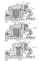
- FIGS 1-3 illustrate a set of three wet brakes 1, 2, 3.
- Each of the brakes 1, 2, 3 comprises a housing 4, 5, 6 which encloses a brake disk set with seven, six and, respectively, three brake disks 7, 8, 9.
- brake disks 7, 8, 9 mean the disks which are connected firmly to an axle 31 of a vehicle wheel. All the brake disks 7, 8, 9 of the respective brake 1, 2, 3 are arranged to interact with two adjacent stator disks 10, 11, 12.
- Each of the brake disks 7, 8, 9 has an annular friction lining on the side of the disk which is intended to be brought into contact with the respective stator disk 10, 11, 12.
- the brake disks 7, 8, 9 have the same dimensions and are of the same type. The three brakes thus have different maximum braking effect values.
- the brake disks 7, 8, 9 are of the same type means that they have essentially the same braking characteristics. To this end, they are suitably manufactured in the same way and of the same material.
- the expression that the brake disks 7, 8, 9 have the same dimensions means that they have essentially the same outside and inside diameters and the same thickness.
- the stator disks 10, 11, 12 are of the same type and size.
- the brake disks 7, 8, 9 can on the other hand be of a different type and size to the stator disks 10, 11, 12.
- the brake 1, 2, 3 comprises a means 17, in the form of a brake piston, intended for actuating the disk set.
- the brake piston 17 is made in one piece with a pressure plate 30 for actuating a disk in the disk set, which disk is arranged adjacent to the brake piston.
- the disk set is compressed between the brake piston and a counterpressure plate 32 in the housing when the brake piston is activated.
- the brake piston 17 defines a space intended for the supply of pressure oil through an opening 19 in the housing.
- the brake comprises a number of sealing rings 18 on the contact surface between the brake piston 17 and the housing 4, 5, 6.
- the housing 4, 5, 6 consists of two housing parts 13-16 which can be separated from one another.
- a first 14 of the housing parts is identical for the three brakes 1, 2, 3.
- This first housing part 14 is intended to be of more complex design in relation to the second housing part 13, 15, 16.
- the first housing part 14 is designed to hold the brake piston 17, and has seals 18 and a connection 19 for the supply of pressure oil to the piston 17.
- Said actuating means 17 is of the same kind for the two brakes.
- the first housing part 14 can also comprise other connections and arrangements, such as an arrangement for brake slack adjustment and an arrangement for returning the piston after braking has been performed, for example a return spring (not shown).
- Identical means that the first housing part 14 has at least the same shape and preferably also essentially the same internal construction, that is to say the same material and structure, for the three brakes 1, 2, 3.
- the design of the second housing part 13, 15, 16 differs for the three brakes.
- One side wall 20, 21, 22 of the second housing part 13, 15, 16, which wall is arranged on the opposite side of the disks to the brake piston 17, is arranged at a different distance from the first housing part 14 depending on the different number of disks in the brakes.
- the side wall 21 of the second brake 2 will be arranged at a shorter distance from the first housing part 14 than the side wall 20 of the first brake 1.
- the side walls 20, 21 and 22 have essentially the same thickness.
- the housings 4, 5, 6 of the three brakes 1, 2, 3 also have the same extent in a direction at right angles to the plane of extension of the disks 10, 11, 12. This means that the brakes 1, 2, 3 have the same mounting dimensions, which in turn means that parts located around the respective brakes can be the same for the three brakes 1, 2, 3.
- the first housing part 14 is more complicated to manufacture than the second housing part 13, 15, 16.
- the housing parts 13, 14, 15, 16 are manufactured by casting with subsequent machining.
- a cost-effective production method can be achieved.
- a reduction in the number of items is achieved, and on the other hand a reduction in weight of the housing assembly.
- FIG 4 illustrates a side view of an articulated or frame-steered vehicle 23, what is referred to as a dumper.
- the dumper 23 comprises a front vehicle part 24 bearing the drive engine and a rear, load-bearing vehicle part 25 which, via a vertical pivot pin 26, is connected to the front vehicle part 24.
- the front and rear vehicle parts 24 and 25 are also interconnected in an articulated manner around a horizontal pivot pin (not shown) so that the vehicle parts can be rotated in relation to one another about a longitudinal axis of the vehicle.
- the dumper 23 has three wheel axles, namely a front axle 27 and two rear axles 28, 29.
- the front wheel axle 27 is provided with the first 1 of said brakes with seven brake disks 7
- a first rear wheel axle 28 is provided with a second 2 of said brakes with six brake disks 8
- the second rear wheel axle 29 is provided with a third 3 of said brakes with three brake disks 9.
Landscapes
- Engineering & Computer Science (AREA)
- General Engineering & Computer Science (AREA)
- Mechanical Engineering (AREA)
- Braking Arrangements (AREA)
- Braking Systems And Boosters (AREA)
- Braking Elements And Transmission Devices (AREA)
Abstract
Description
- The present invention relates to a set of at least two wet brakes according to the preamble of claim 1. Said rotating member suitably consists of a hub for a wheel of a vehicle. Said actuating means preferably consists of a hydraulic piston. The invention also relates to a vehicle according to the preamble of
claim 7. The invention will be described below as implemented in a vehicle in the form of an articulated or frame-steered vehicle, what is referred to as a dumper. This is a preferred but in no way limiting application of the invention. - According to the prior art, it is known to manufacture two brakes intended for different maximum braking effect values with different dimensions of the disks in the disk sets of the brakes, that is to say the disks of one of the brakes are of a first size and the disks of the other brake are of a second size. In this connection, the housings which enclose the two disk sets are also of different sizes.
- For the purpose of bringing about more cost-effective manufacture of brakes for different maximum braking effect values, brakes have been developed with an increased number of similar parts. According to the prior art, it is known to use a similar housing for the brakes, the same dimensions for the disks and the same number of disks in the disk sets of the different brakes. The different braking effect is achieved by virtue of the disk sets having a different number of disks which are active for braking. In the brake with smaller maximum braking effect, the disk set is filled up with a number of filler disks, that is to say disks which are not adapted for contributing to the braking effect. As these filler disks are intended only for filling up the disk set, use is made of an inexpensive material, for example plastic material, so that these can be produced cost-effectively.
- A primary object of the invention is to produce a set of at least two wet brakes with different maximum braking effect values, which affords opportunities for more cost-effective manufacture of the brakes in relation to the prior art. A secondary object is to produce said wet brakes with reduced weight in relation to the prior art.
- These objects are achieved by virtue of the fact that all of said disks in each of the disk sets are arranged so as to interact with at least one adjacent disk in order to produce said braking effect, that a first of the housing parts is identical in the two brakes, and that a second of the housing parts is of different design in the two brakes. The housing parts are usually produced by casting followed by machining. Said first housing part, which is of the same kind for the two different brakes, is intended to comprise at least the majority of and preferably all the arrangements and connections which are required for the brake, such as the brake piston connection, connection ports for operating oil and cooling oil, an arrangement for indicating wear of the disks etc. The design of the first housing part is therefore more complex than that of the second housing part. Owing to the fact that the first housing part is identical for the two brakes, the housings can be manufactured in a cost-effective manner with minimum material consumption. Owing to the fact that the entire inner space of the brake, in which the disk set is arranged, can thus be used for disks which are active for braking, opportunities are afforded for a more space-effective brake as far as the brake with smaller maximum braking effect is concerned.
- According to a preferred embodiment of the invention, said different design of the second housing part in the two brakes consists in that one side wall of the second housing part, which faces a flat side of an outer disk in the disk set, is arranged at a shorter distance from the first housing part in the second brake than in the first brake. This is an advantageous embodiment of the housing, and it affords opportunities for a space-effective housing.
- According to another preferred embodiment of the invention, the two said housing parts of the first brake have the same extent in a direction at right angles to the plane of extension of the disks as the two said housing parts of the second brake. Owing to the fact that the brakes with different maximum braking effect values have the same longitudinal extent in said direction, parts located around the brake can be arranged in the same manner for the different brakes.
- Another object of the invention is to produce a vehicle comprising a front axle and at least one rear axle, on which axles the wheels of the vehicle are arranged, and a wet brake for the respective wheels according to the preamble of
claim 7, which vehicle affords opportunities for more cost-effective production of the vehicle in relation to the prior art. - This object is achieved by virtue of the fact that all said disks in each of the disk sets are arranged so as to interact with at least one adjacent disk in order to produce said braking effect, that a first of the housing parts is identical in the two brakes, and that a second of the housing parts is of different design in the two brakes.
- Other advantageous embodiments and advantages of the invention emerge from the other patent claims and the description below.
- The invention is described in greater detail below, with reference to the embodiment shown in the accompanying drawings.
- Figures 1-3 illustrate in diagrammatic sectional views a set of three wet brakes with seven, six and, respectively, three brake disks according to a preferred embodiment of the invention.
- Figure 4 illustrates in a side view an articulated dumper with three wheel axles, which are provided with the brakes according to Figures 1-3.
- Figures 1-3 illustrate a set of three
wet brakes brakes housing 4, 5, 6 which encloses a brake disk set with seven, six and, respectively, threebrake disks 7, 8, 9. Here,brake disks 7, 8, 9 mean the disks which are connected firmly to anaxle 31 of a vehicle wheel. All thebrake disks 7, 8, 9 of therespective brake adjacent stator disks 10, 11, 12. Each of thebrake disks 7, 8, 9 has an annular friction lining on the side of the disk which is intended to be brought into contact with therespective stator disk 10, 11, 12. Thebrake disks 7, 8, 9 have the same dimensions and are of the same type. The three brakes thus have different maximum braking effect values. - The expression that the
brake disks 7, 8, 9 are of the same type means that they have essentially the same braking characteristics. To this end, they are suitably manufactured in the same way and of the same material. The expression that thebrake disks 7, 8, 9 have the same dimensions means that they have essentially the same outside and inside diameters and the same thickness. In the same way, thestator disks 10, 11, 12 are of the same type and size. Thebrake disks 7, 8, 9 can on the other hand be of a different type and size to thestator disks 10, 11, 12. - The
brake means 17, in the form of a brake piston, intended for actuating the disk set. Thebrake piston 17 is made in one piece with apressure plate 30 for actuating a disk in the disk set, which disk is arranged adjacent to the brake piston. The disk set is compressed between the brake piston and acounterpressure plate 32 in the housing when the brake piston is activated. Together with thehousing 4, 5, 6, thebrake piston 17 defines a space intended for the supply of pressure oil through an opening 19 in the housing. The brake comprises a number ofsealing rings 18 on the contact surface between thebrake piston 17 and thehousing 4, 5, 6. - The
housing 4, 5, 6 consists of two housing parts 13-16 which can be separated from one another. A first 14 of the housing parts is identical for the threebrakes first housing part 14 is intended to be of more complex design in relation to thesecond housing part first housing part 14 is designed to hold thebrake piston 17, and hasseals 18 and a connection 19 for the supply of pressure oil to thepiston 17. Said actuating means 17 is of the same kind for the two brakes. Thefirst housing part 14 can also comprise other connections and arrangements, such as an arrangement for brake slack adjustment and an arrangement for returning the piston after braking has been performed, for example a return spring (not shown). Identical means that thefirst housing part 14 has at least the same shape and preferably also essentially the same internal construction, that is to say the same material and structure, for the threebrakes - The design of the
second housing part side wall second housing part brake piston 17, is arranged at a different distance from thefirst housing part 14 depending on the different number of disks in the brakes. In this connection, for example, theside wall 21 of thesecond brake 2 will be arranged at a shorter distance from thefirst housing part 14 than theside wall 20 of the first brake 1. Theside walls housings 4, 5, 6 of the threebrakes disks 10, 11, 12. This means that thebrakes brakes - On account of its more complex construction, the
first housing part 14 is more complicated to manufacture than thesecond housing part housing parts first housing part 14 constant in the threebrakes second housing part - Figure 4 illustrates a side view of an articulated or frame-steered
vehicle 23, what is referred to as a dumper. Thedumper 23 comprises afront vehicle part 24 bearing the drive engine and a rear, load-bearing vehicle part 25 which, via avertical pivot pin 26, is connected to thefront vehicle part 24. The front andrear vehicle parts - The
dumper 23 has three wheel axles, namely afront axle 27 and tworear axles dumper 23, thefront wheel axle 27 is provided with the first 1 of said brakes with sevenbrake disks 7, a firstrear wheel axle 28 is provided with a second 2 of said brakes with six brake disks 8, and the secondrear wheel axle 29 is provided with a third 3 of said brakes with three brake disks 9. By virtue of the invention, it is possible to produce the articulateddumper 23 withbrakes - The invention is not to be considered as being limited to the illustrative embodiments described above, but a number of further variants and modifications are possible within the scope of the patent claims below. It is pointed out in particular that the person skilled in the art will be capable of effecting alterations to the invention without for that reason leaving the scope of the patent protection. The number of brake disks selected in the embodiment described above is of course to be regarded as only an example and can be varied within the scope of the patent claims below.
Claims (13)
- A set of at least two wet brakes (1, 2, 3), the brakes being adapted to produce different maximum braking force values, each of the brakes comprising a housing (4, 5, 6) with two housing parts (13-16) which can be separated from one another, a disk set enclosed by the housing, and a means (17) for actuating the disk set for the purpose of producing a braking effect on a rotating member connected to the disk set, the disk set of a first (1) of the brakes comprising a first number of disks (7, 10) which are active for braking, and the disk set of a second of the brakes (2 or 3), which brake is intended for a smaller maximum braking force in relation to the first brake, comprising, in relation to the first number, a smaller number of disks (8, 11 or, respectively, 9, 12) which are active for braking of the same size as the disks in the first brake, characterized in that all of said disks (7-9) in each of the disk sets are arranged so as to interact with at least one adjacent disk (10-12) in order to produce said braking effect, in that a first (14) of the housing parts is identical in the two brakes, and in that a second (13, 15, 16) of the housing parts is of different design in the two brakes.
- The brake set as claimed in claim 1, characterized in that said different design of the second housing part (13, 15, 16) in the two brakes (1-3) consists in that one side wall (20-22) of the second housing part, which faces a flat side of an outer disk in the disk set, is arranged at a shorter distance from the first housing part (14) in the second brake than in the first brake.
- The brake set as claimed in claim 1 or 2, characterized in that the two said housing parts (13, 14) of the first brake (1) have the same extent in a direction at right angles to the plane of extension of the disks as the two said housing parts (15, 14 or 16, 14) of the second brake (2 or 3).
- The brake set as claimed in any one of claims 1-3, characterized in that said actuating means (17) is arranged in the first housing part (14).
- The brake set as claimed in any one of claims 1-4, characterized in that said actuating means (17) consists of a hydraulic piston.
- The brake set as claimed in any one of claims 1-5, characterized in that said disks (8, 11 or, respectively, 9, 12) active for braking in the disk set of the second brake (2 or 3) are of the same type as the disks (7, 10) in the first brake (1).
- A vehicle (23) comprising a front axle (27) and at least one rear axle (28, 29), on which axles the wheels of the vehicle are arranged, and a wet brake (1, 2, 3) for the respective wheels, the brakes being arranged so as to produce different maximum braking force values on the axles, each of the brakes comprising a housing (4-6) with two housing parts (13-16) which can be separated from one another, a disk set enclosed by the housing, and a means (17) for actuating the disk set for the purpose of producing a braking effect on the vehicle, the disk set of a first (1) of the brakes, which brake is arranged at a wheel on a first (27) of the axles, comprising a first number of disks (7, 10) which are active for braking, that the disk set of a second of the brakes (2 or 3), which brake is arranged at a wheel of a second (28 or, respectively, 29) of the axles and intended for a smaller maximum braking force in relation to the first brake, comprising, in relation to the first number, a smaller number of disks (8, 11 or, respectively, 9, 12) which are active for braking of the same size as the disks in the first brake, characterized in that all of said disks (7-9) in each of the disk sets are arranged so as to interact with at least one adjacent disk (10-12) in order to produce said braking effect, in that a first (14) of the housing parts is identical in the two brakes, and in that a second (13, 15, 16) of the housing parts is of different design in the two brakes.
- The vehicle as claimed in claim 7, characterized in that said different design of the second housing part (13, 15, 16) in the two brakes consists in that one side wall (20, 21, 22) of the second housing part, which faces a flat side of an outer disk in the disk set, is arranged at a shorter distance from the first housing part (14) in the first brake than in the second brake.
- The vehicle as claimed in claim 7 or 8, characterized in that the two said housing parts (13, 14) of the first brake (1) have the same extent in a direction at right angles to the plane of extension of the disks as the two said housing parts of the second brake (2 or 3).
- The vehicle as claimed in any one of claims 7-9, characterized in that said actuating means (17) is arranged in the first housing part (14).
- The vehicle as claimed in any one of claims 7-10, characterized in that said actuating means (17) consists of a hydraulic piston.
- The vehicle as claimed in any one of claims 7-11, characterized in that said disks (8, 11 or, respectively, 9, 12) active for braking in the disk set of the second brake (2 or 3) are of the same type as the disks (7, 10) in the first brake (1).
- The vehicle as claimed in any one of claims 7-12, characterized in that the vehicle (23) consists of an articulated dumper.
Applications Claiming Priority (3)
| Application Number | Priority Date | Filing Date | Title |
|---|---|---|---|
| SE0002637A SE521910C2 (en) | 2000-07-12 | 2000-07-12 | Set of wet brakes and vehicles with said brake set |
| SE0002637 | 2000-07-12 | ||
| PCT/SE2001/001515 WO2002004832A1 (en) | 2000-07-12 | 2001-06-29 | A set of brakes and a vehicle with said set of wet brakes |
Publications (2)
| Publication Number | Publication Date |
|---|---|
| EP1303709A1 EP1303709A1 (en) | 2003-04-23 |
| EP1303709B1 true EP1303709B1 (en) | 2006-11-15 |
Family
ID=20280471
Family Applications (1)
| Application Number | Title | Priority Date | Filing Date |
|---|---|---|---|
| EP01950125A Expired - Lifetime EP1303709B1 (en) | 2000-07-12 | 2001-06-29 | A set of brakes and a vehicle with said set of wet brakes |
Country Status (7)
| Country | Link |
|---|---|
| US (1) | US7506730B2 (en) |
| EP (1) | EP1303709B1 (en) |
| AT (1) | ATE345453T1 (en) |
| AU (1) | AU2001271154A1 (en) |
| DE (1) | DE60124553T2 (en) |
| SE (1) | SE521910C2 (en) |
| WO (1) | WO2002004832A1 (en) |
Families Citing this family (11)
| Publication number | Priority date | Publication date | Assignee | Title |
|---|---|---|---|---|
| US20050252730A1 (en) * | 2004-05-14 | 2005-11-17 | Ernst Auer | Wheel hub |
| US9085285B2 (en) | 2006-01-19 | 2015-07-21 | Hydro-Aire, Inc. | System and method for aircraft brake metering to alleviate structural loading |
| US7410224B2 (en) * | 2006-01-19 | 2008-08-12 | Hydro-Aire, Inc. | Method and system to increase electric brake clamping force accuracy |
| US9291133B2 (en) | 2011-12-20 | 2016-03-22 | Caterpillar Inc. | Shaft arrangement for an axial piston pump assembly |
| US8662277B2 (en) | 2011-12-22 | 2014-03-04 | Fairfield Manufacturing Company, Inc. | Planetary gearbox with integral service brake |
| US8663058B2 (en) | 2012-01-23 | 2014-03-04 | Caterpillar Inc. | Brake assembly having piloted park brake housing |
| US8626410B2 (en) | 2012-01-23 | 2014-01-07 | Caterpillar Inc. | Powertrain system having lockable differential |
| US9169884B2 (en) | 2012-01-23 | 2015-10-27 | Caterpillar Inc. | Wet brake assembly |
| US9429227B2 (en) | 2014-02-19 | 2016-08-30 | Fairfield Manufacturing Company, Inc. | Planetary gearbox with integral service brake |
| CN105650147A (en) * | 2015-02-04 | 2016-06-08 | 湖北康晨安宝矿业设备有限责任公司 | Hydraulic brake device |
| CN106240428B (en) * | 2016-08-18 | 2019-03-12 | 陕西同力重工股份有限公司 | Underground dumper |
Family Cites Families (13)
| Publication number | Priority date | Publication date | Assignee | Title |
|---|---|---|---|---|
| FR2314399A1 (en) * | 1975-06-13 | 1977-01-07 | Ferodo Sa | DISC BRAKE |
| FR2512144A1 (en) * | 1981-08-25 | 1983-03-04 | Lucas Ind Plc | IMPROVEMENTS IN HIGH-CAPACITY DISK BRAKES, ESPECIALLY FOR HEAVY WEIGHTS |
| US4529067A (en) * | 1983-08-31 | 1985-07-16 | Rockwell International Corporation | Multiple disc brake |
| US4890699A (en) * | 1988-07-28 | 1990-01-02 | The B. F. Goodrich Company | Wet disc friction brake with casing rods extending through stator bores |
| US5174420A (en) * | 1991-05-02 | 1992-12-29 | Clark Equipment Company | Wet disc brake |
| SE509044C2 (en) * | 1995-11-29 | 1998-11-30 | K S Technology Hb | Brake device |
| SE506828C2 (en) * | 1996-06-13 | 1998-02-16 | Volvo Wheel Loaders Ab | Mechanically adjustable wear indicator |
| JP3722451B2 (en) * | 1996-06-26 | 2005-11-30 | 株式会社小松製作所 | Self-propelled vehicle |
| US5944147A (en) * | 1996-06-28 | 1999-08-31 | Alliedsignal Inc. | Integrated aircraft wheel, brake and axle |
| US6532637B1 (en) * | 1997-06-06 | 2003-03-18 | Honeywell International Inc. | Method of converting an aircraft brake assembly and a convertible aircraft brake assembly |
| US6116383A (en) * | 1998-10-21 | 2000-09-12 | Meritor Heavy Vehicle Systems, Llc | Wet disc pack with variable co-efficients of friction discs |
| US6264009B1 (en) * | 1999-06-03 | 2001-07-24 | Meritor Heavy Vehicle Systems, Llc | Multi-stage wet disc brake |
| US6581730B1 (en) * | 1999-09-13 | 2003-06-24 | Goodrich Corporation | Aircraft landing gear with integrated brake actuation system |
-
2000
- 2000-07-12 SE SE0002637A patent/SE521910C2/en not_active IP Right Cessation
-
2001
- 2001-06-29 AT AT01950125T patent/ATE345453T1/en not_active IP Right Cessation
- 2001-06-29 EP EP01950125A patent/EP1303709B1/en not_active Expired - Lifetime
- 2001-06-29 AU AU2001271154A patent/AU2001271154A1/en not_active Abandoned
- 2001-06-29 DE DE60124553T patent/DE60124553T2/en not_active Expired - Lifetime
- 2001-06-29 WO PCT/SE2001/001515 patent/WO2002004832A1/en not_active Ceased
-
2003
- 2003-01-13 US US10/248,355 patent/US7506730B2/en not_active Expired - Fee Related
Also Published As
| Publication number | Publication date |
|---|---|
| ATE345453T1 (en) | 2006-12-15 |
| AU2001271154A1 (en) | 2002-01-21 |
| DE60124553T2 (en) | 2007-09-20 |
| US7506730B2 (en) | 2009-03-24 |
| WO2002004832A1 (en) | 2002-01-17 |
| SE0002637L (en) | 2002-01-13 |
| SE0002637D0 (en) | 2000-07-12 |
| EP1303709A1 (en) | 2003-04-23 |
| SE521910C2 (en) | 2003-12-16 |
| DE60124553D1 (en) | 2006-12-28 |
| US20030079947A1 (en) | 2003-05-01 |
Similar Documents
| Publication | Publication Date | Title |
|---|---|---|
| EP1303709A1 (en) | A set of brakes and a vehicle with said set of wet brakes | |
| EP1534974B1 (en) | Caliper for a disc brake | |
| CN103671643A (en) | Wet type vehicle brake braking force increasing mechanism | |
| WO2008047840A1 (en) | Brake caliper for disk brake | |
| CN201152330Y (en) | Allterrain vehicle hydraulic braking system three-piston brake cylinder | |
| JP2001107994A (en) | Opposed-piston-type disk barke and manufacture thereof | |
| JP2005048945A (en) | Air brake and actuator assembly | |
| CN217633558U (en) | Wet brake with double friction pairs | |
| US6910554B2 (en) | Caliper assembly for a disc brake | |
| US20130074491A1 (en) | Sub Master Cylinder and Brake Apparatus Having The Same | |
| US5167303A (en) | Disc brake | |
| US11149813B2 (en) | Hydraulic brake system | |
| JP4461082B2 (en) | Caliper body for disc brakes for vehicles | |
| JP2006105326A (en) | Vehicle disc brake | |
| US20030042791A1 (en) | Anti-vibration brake system | |
| JPH11222109A (en) | Brake equipment | |
| KR101419538B1 (en) | Four-piston aluminium brake caliper for racing | |
| JPS62261737A (en) | Differential device conducting self-differntial stop for automobile | |
| JP3863870B2 (en) | Split caliper body for vehicle disc brakes | |
| CN102364146A (en) | Brake wheel cylinder assembly for preventing collision between pistons | |
| KR100326380B1 (en) | A connecting apparatus of guide pin of disk brake for vehicle | |
| KR20060062894A (en) | Automotive caliper brakes for easy removal and mating | |
| JP2006336763A (en) | Disc brake | |
| EP4036431A1 (en) | Caliper body for vehicular disc brake | |
| WO1999044873A1 (en) | Hydraulic control unit for an anti-lock brake system having a pump for performing pressure dump function |
Legal Events
| Date | Code | Title | Description |
|---|---|---|---|
| PUAI | Public reference made under article 153(3) epc to a published international application that has entered the european phase |
Free format text: ORIGINAL CODE: 0009012 |
|
| 17P | Request for examination filed |
Effective date: 20030212 |
|
| AK | Designated contracting states |
Designated state(s): AT BE CH CY DE DK ES FI FR GB GR IE IT LI LU MC NL PT SE TR |
|
| AX | Request for extension of the european patent |
Extension state: AL LT LV MK RO SI |
|
| REG | Reference to a national code |
Ref country code: SE Ref legal event code: TRGR |
|
| GRAP | Despatch of communication of intention to grant a patent |
Free format text: ORIGINAL CODE: EPIDOSNIGR1 |
|
| GRAS | Grant fee paid |
Free format text: ORIGINAL CODE: EPIDOSNIGR3 |
|
| GRAA | (expected) grant |
Free format text: ORIGINAL CODE: 0009210 |
|
| AK | Designated contracting states |
Kind code of ref document: B1 Designated state(s): AT BE CH CY DE DK ES FI FR GB GR IE IT LI LU MC NL PT SE TR |
|
| PG25 | Lapsed in a contracting state [announced via postgrant information from national office to epo] |
Ref country code: IT Free format text: LAPSE BECAUSE OF FAILURE TO SUBMIT A TRANSLATION OF THE DESCRIPTION OR TO PAY THE FEE WITHIN THE PRESCRIBED TIME-LIMIT;WARNING: LAPSES OF ITALIAN PATENTS WITH EFFECTIVE DATE BEFORE 2007 MAY HAVE OCCURRED AT ANY TIME BEFORE 2007. THE CORRECT EFFECTIVE DATE MAY BE DIFFERENT FROM THE ONE RECORDED. Effective date: 20061115 Ref country code: LI Free format text: LAPSE BECAUSE OF FAILURE TO SUBMIT A TRANSLATION OF THE DESCRIPTION OR TO PAY THE FEE WITHIN THE PRESCRIBED TIME-LIMIT Effective date: 20061115 Ref country code: BE Free format text: LAPSE BECAUSE OF FAILURE TO SUBMIT A TRANSLATION OF THE DESCRIPTION OR TO PAY THE FEE WITHIN THE PRESCRIBED TIME-LIMIT Effective date: 20061115 Ref country code: CH Free format text: LAPSE BECAUSE OF FAILURE TO SUBMIT A TRANSLATION OF THE DESCRIPTION OR TO PAY THE FEE WITHIN THE PRESCRIBED TIME-LIMIT Effective date: 20061115 Ref country code: NL Free format text: LAPSE BECAUSE OF FAILURE TO SUBMIT A TRANSLATION OF THE DESCRIPTION OR TO PAY THE FEE WITHIN THE PRESCRIBED TIME-LIMIT Effective date: 20061115 Ref country code: FI Free format text: LAPSE BECAUSE OF FAILURE TO SUBMIT A TRANSLATION OF THE DESCRIPTION OR TO PAY THE FEE WITHIN THE PRESCRIBED TIME-LIMIT Effective date: 20061115 Ref country code: AT Free format text: LAPSE BECAUSE OF FAILURE TO SUBMIT A TRANSLATION OF THE DESCRIPTION OR TO PAY THE FEE WITHIN THE PRESCRIBED TIME-LIMIT Effective date: 20061115 |
|
| REG | Reference to a national code |
Ref country code: GB Ref legal event code: FG4D |
|
| REG | Reference to a national code |
Ref country code: CH Ref legal event code: EP |
|
| REF | Corresponds to: |
Ref document number: 60124553 Country of ref document: DE Date of ref document: 20061228 Kind code of ref document: P |
|
| REG | Reference to a national code |
Ref country code: IE Ref legal event code: FG4D |
|
| PG25 | Lapsed in a contracting state [announced via postgrant information from national office to epo] |
Ref country code: DK Free format text: LAPSE BECAUSE OF FAILURE TO SUBMIT A TRANSLATION OF THE DESCRIPTION OR TO PAY THE FEE WITHIN THE PRESCRIBED TIME-LIMIT Effective date: 20070215 |
|
| PG25 | Lapsed in a contracting state [announced via postgrant information from national office to epo] |
Ref country code: ES Free format text: LAPSE BECAUSE OF FAILURE TO SUBMIT A TRANSLATION OF THE DESCRIPTION OR TO PAY THE FEE WITHIN THE PRESCRIBED TIME-LIMIT Effective date: 20070226 |
|
| PG25 | Lapsed in a contracting state [announced via postgrant information from national office to epo] |
Ref country code: PT Free format text: LAPSE BECAUSE OF FAILURE TO SUBMIT A TRANSLATION OF THE DESCRIPTION OR TO PAY THE FEE WITHIN THE PRESCRIBED TIME-LIMIT Effective date: 20070416 |
|
| NLV1 | Nl: lapsed or annulled due to failure to fulfill the requirements of art. 29p and 29m of the patents act | ||
| REG | Reference to a national code |
Ref country code: CH Ref legal event code: PL |
|
| EN | Fr: translation not filed | ||
| EN | Fr: translation not filed | ||
| PLBE | No opposition filed within time limit |
Free format text: ORIGINAL CODE: 0009261 |
|
| STAA | Information on the status of an ep patent application or granted ep patent |
Free format text: STATUS: NO OPPOSITION FILED WITHIN TIME LIMIT |
|
| 26N | No opposition filed |
Effective date: 20070817 |
|
| PG25 | Lapsed in a contracting state [announced via postgrant information from national office to epo] |
Ref country code: MC Free format text: LAPSE BECAUSE OF NON-PAYMENT OF DUE FEES Effective date: 20070630 |
|
| GBPC | Gb: european patent ceased through non-payment of renewal fee |
Effective date: 20070629 |
|
| PG25 | Lapsed in a contracting state [announced via postgrant information from national office to epo] |
Ref country code: GR Free format text: LAPSE BECAUSE OF FAILURE TO SUBMIT A TRANSLATION OF THE DESCRIPTION OR TO PAY THE FEE WITHIN THE PRESCRIBED TIME-LIMIT Effective date: 20070216 Ref country code: FR Free format text: LAPSE BECAUSE OF FAILURE TO SUBMIT A TRANSLATION OF THE DESCRIPTION OR TO PAY THE FEE WITHIN THE PRESCRIBED TIME-LIMIT Effective date: 20070629 |
|
| PG25 | Lapsed in a contracting state [announced via postgrant information from national office to epo] |
Ref country code: GB Free format text: LAPSE BECAUSE OF NON-PAYMENT OF DUE FEES Effective date: 20070629 Ref country code: IE Free format text: LAPSE BECAUSE OF NON-PAYMENT OF DUE FEES Effective date: 20070629 |
|
| PG25 | Lapsed in a contracting state [announced via postgrant information from national office to epo] |
Ref country code: FR Free format text: LAPSE BECAUSE OF FAILURE TO SUBMIT A TRANSLATION OF THE DESCRIPTION OR TO PAY THE FEE WITHIN THE PRESCRIBED TIME-LIMIT Effective date: 20061115 |
|
| PG25 | Lapsed in a contracting state [announced via postgrant information from national office to epo] |
Ref country code: CY Free format text: LAPSE BECAUSE OF FAILURE TO SUBMIT A TRANSLATION OF THE DESCRIPTION OR TO PAY THE FEE WITHIN THE PRESCRIBED TIME-LIMIT Effective date: 20061115 Ref country code: LU Free format text: LAPSE BECAUSE OF NON-PAYMENT OF DUE FEES Effective date: 20070629 |
|
| PG25 | Lapsed in a contracting state [announced via postgrant information from national office to epo] |
Ref country code: TR Free format text: LAPSE BECAUSE OF FAILURE TO SUBMIT A TRANSLATION OF THE DESCRIPTION OR TO PAY THE FEE WITHIN THE PRESCRIBED TIME-LIMIT Effective date: 20061115 |
|
| PGFP | Annual fee paid to national office [announced via postgrant information from national office to epo] |
Ref country code: SE Payment date: 20110613 Year of fee payment: 11 |
|
| PGFP | Annual fee paid to national office [announced via postgrant information from national office to epo] |
Ref country code: DE Payment date: 20110622 Year of fee payment: 11 |
|
| REG | Reference to a national code |
Ref country code: SE Ref legal event code: EUG |
|
| PG25 | Lapsed in a contracting state [announced via postgrant information from national office to epo] |
Ref country code: SE Free format text: LAPSE BECAUSE OF NON-PAYMENT OF DUE FEES Effective date: 20120630 |
|
| REG | Reference to a national code |
Ref country code: DE Ref legal event code: R119 Ref document number: 60124553 Country of ref document: DE Effective date: 20130101 |
|
| PG25 | Lapsed in a contracting state [announced via postgrant information from national office to epo] |
Ref country code: DE Free format text: LAPSE BECAUSE OF NON-PAYMENT OF DUE FEES Effective date: 20130101 |