EP1303164B1 - Microphone having a flexible printed circuit board for mounting components - Google Patents
Microphone having a flexible printed circuit board for mounting components Download PDFInfo
- Publication number
- EP1303164B1 EP1303164B1 EP02079187.7A EP02079187A EP1303164B1 EP 1303164 B1 EP1303164 B1 EP 1303164B1 EP 02079187 A EP02079187 A EP 02079187A EP 1303164 B1 EP1303164 B1 EP 1303164B1
- Authority
- EP
- European Patent Office
- Prior art keywords
- assembly
- diaphragm
- backplate
- circuit board
- printed circuit
- Prior art date
- Legal status (The legal status is an assumption and is not a legal conclusion. Google has not performed a legal analysis and makes no representation as to the accuracy of the status listed.)
- Expired - Lifetime
Links
Images






Classifications
-
- H—ELECTRICITY
- H04—ELECTRIC COMMUNICATION TECHNIQUE
- H04R—LOUDSPEAKERS, MICROPHONES, GRAMOPHONE PICK-UPS OR LIKE ACOUSTIC ELECTROMECHANICAL TRANSDUCERS; ELECTRIC HEARING AIDS; PUBLIC ADDRESS SYSTEMS
- H04R19/00—Electrostatic transducers
- H04R19/01—Electrostatic transducers characterised by the use of electrets
- H04R19/016—Electrostatic transducers characterised by the use of electrets for microphones
-
- H—ELECTRICITY
- H05—ELECTRIC TECHNIQUES NOT OTHERWISE PROVIDED FOR
- H05K—PRINTED CIRCUITS; CASINGS OR CONSTRUCTIONAL DETAILS OF ELECTRIC APPARATUS; MANUFACTURE OF ASSEMBLAGES OF ELECTRICAL COMPONENTS
- H05K1/00—Printed circuits
- H05K1/18—Printed circuits structurally associated with non-printed electric components
- H05K1/189—Printed circuits structurally associated with non-printed electric components characterised by the use of flexible or folded printed circuits
Definitions
- This invention relates generally to electroacoustic transducers and, in particular, to an electroacoustic transducer having a flexible printed circuit board on which the internal components of the transducer are mounted.
- Electroacoustic transducers which convert electrical energy into sound energy and vice versa, have been known for decades. They are useful for various purposes, including telecommunications equipment and hearing instruments, such as hearing aids (or generally “listening devices") that are located outside the ear or that fit within the ear canal.
- a conventional listening device includes a miniature microphone that receives acoustic waves and converts the acoustic waves to an audio signal. That audio signal is then processed (e.g., amplified) and sent to the receiver of the hearing aid or listening device. The receiver then converts the processed signal to an acoustic signal that is broadcast towards the eardrum.
- the state-of-the-art transducer type used for these applications is the electret microphone.
- the construction of the electret microphone consists of three parts: a microphone housing, an impedance conversion circuit, and the microphone cartridge.
- a cartridge typically consists of a rigid plate ("backplate") and a metallized polymer diaphragm separated by a thin spacer.
- the diaphragm and the backplate form the plates of a variable capacitor.
- a dielectric layer in either the backplatc or diaphragm is permanently electrically charged (“electret").
- An incoming sound wave causes the diaphragm to move relative to the backplate, resulting in a capacitance change.
- the change in capacitance alters the electrical field strength from the fixed charge and, thus, causes a voltage change across the capacitor.
- electret microphones typically include an internal buffer amplifier (or impedance conversion circuit). Both the backplate and the diaphragm of the cartridge must be connected with the buffer amplifier. Generally, either the backplate or the diaphragm ("reference") is connected with the amplifier via the microphone housing. The other (“signal”) is connected with the amplifier by a wire, which requires the use of a soldering process and/or a small drop of electrically conductive adhesive. This is often a manual step subject to human error and is time consuming.
- the present invention solves the aforementioned problems.
- the present invention involves a novel method and structure in which a flexible printed circuit board (“flex-print”) serves two functions: separating the diaphragm and backplate, and electrically connecting the cartridge and the buffer amplifier.
- the flex-print includes a spacer portion that maintains the appropriate distance between the diaphragm and the backplate, and an integral lead portion having an electrical conductor that serves as the signal path for transmitting the electrical signal from the cartridge to the buffer amplifier.
- the spacer portion has an electrical conductor that is electrically coupled to the diaphragm or backplate and the electrical conductor of the integral lead portion.
- the integral lead portion eliminates the need for soldering or gluing a lead wire between the two components.
- the integral lead portion of the flex-print may optionally include a second electrical conductor that provides the reference path from the cartridge to the amplifier.
- the microphone housing is not needed to provide the reference path to the buffer amplifier.
- the flex-print may also be used as the carrier for the buffer amplifier and its associated circuitry.
- the flex-print includes another mounting section for the buffer amplifier and its associated circuitry.
- the integral lead portion has the spacer portion at one end and the amplifier mounting section on the other end.
- the buffer amplifier is a small integrated semiconductor circuit that is connected with the leads by bonding wires.
- Elements not integrated with the semiconductor, e.g., resistors and capacitors, can also be surface mounted on the flex-print by using SMD components.
- the flip-chip technology can be used for the buffer amplifier.
- the flex-print may also be used as a portion of the diaphragm subassembly.
- the diaphragm is a metallized polymer film that is stretched in a ring-shaped or rectangular frame. While this frame can be made of a separate piece of flex-print, the frame can also be made from the same piece of flex-print that is used for the spacer and its integral lead portion. As such, the flex-print includes a region for mounting the diaphragm film that is eventually folded over the spacer portion of the flex-print.
- the backplate subassembly includes a rigid plate with a conductive portion and a charged layer.
- the rigid plate can be made from flex-print material.
- the rigid plate can also be manufactured from the same piece of flex-print as was used for the spacer.
- a dielectric film can be laminated on top of the backplate to provide for storage of a permanent electrical charge.
- the flex-print includes a region for mounting the moveable diaphragm.
- the backplate is located on another part of the flex-print.
- a spacer element is made from another part of the flex-print and maintains a certain spacing between the moveable diaphragm and the backplate after folding the flex-print.
- the spacer element has an internally conductive element(s) leading to and being in electrical contact with the backplate and/or the moveable diaphragm.
- the spacer element includes an integral lead portion made of the flex-print that includes a signal path for transmitting the electrical signal to the buffer amplifier, which can be located on yet another portion of the flex-print.
- the manufacturing process of the assembly can be performed while it is in a horizontal plane. After all of the components are attached to the flex-print, it can be folded or bent to a predetermined orientation so as to fit within a housing of a microphone or receiver.
- FIG. 1 illustrates a microphone cartridge 10 having a spacer subassembly 12 made of a flexible printed circuit board material, i.e., flex-print.
- the spacer subassembly 12 which has an annular shape spacing section 13, separates a diaphragm subassembly 14 from a backplate subassembly 16.
- the flex-print e.g., polyimide
- the diaphragm subassembly 14 includes a thin, moveable metallized (polymer) diaphragm 18 that is mounted on a frame 20.
- the backplate assembly 16 includes a rigid base layer 22 and a charged dielectric layer 24, which may be a Teflon® coating having a surface charge or a layer of special electret film (“EMFi”), such as one disclosed in U.S. Patent Nos. 4,654,546 and 5,757,090 to Kirjavinen.
- EMFi electret film
- the spacer subassembly 12 maintains the appropriate spacing between the metallized diaphragm 18 and the charged layer 24 after the diaphragm subassembly 14 and the backplate subassembly 16 have been stacked on the spacer subassembly 12.
- the flex-print spacer subassembly 12 has an exposed, annular metal trace 26 ( FIG. 2 ) on one side of the spacer subassembly 12 and a signal path 28 on an integral lead portion 29.
- the metal trace 26, which is connected to the signal path 28, is in electrical contact with the diaphragm 18.
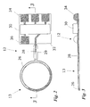
- FIGS. 2 and 3 show a top view and a cross-sectional view of the unfolded spacer subassembly 12, with the cross-section in FIG. 3 being taken along line 3-3 in FIG. 2 .
- FIGS. 2 and 3 illustrate the connection of the integral lead portion 29 to a small circuit board, which is an amplifier portion 32 of the spacer subassembly 12.
- the signal path 28 of the integral lead portion 29 electrically transmits the electric signal from the diaphragm 18 to a buffer amplifier 30 on the amplifier portion 32.
- the backplate 16 provides the reference voltage and is connected with the reference terminal 36 of the buffer amplifier 30 via the metal housing of the microphone (not shown).
- the amplifier portion 32 of the spacer subassembly 12 has three output terminals 34 that transmit the output signal from the buffer amplifier 30 and provide the supply voltage.
- the amplifier portion 32 on which the buffer amplifier 30 is mounted is made from the same flex-print material as the spacing portion 13 and the integral lead portion 29 of the spacer subassembly 12.
- the integral lead portion 29 and its associated signal path 28, however, can terminate before the buffer amplifier 30.
- the integral lead portion 29 has a simple terminal at the end of the signal path 28 that can be used for connection to the buffer amplifier 30, which is mounted on a different structure.
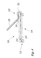
- FIG. 4 shows an alternative cartridge 10' where the positions of the diaphragm subassembly 14 and the backplate subassembly 16 have been swapped.
- the signal path 28 at a bend region 32 of the integral lead portion 29 (after it transitions from the flat shape of FIGS. 2 and 3 to the folded shape of FIG. 4 ) is held on the conductive base layer 22' of the backplate subassembly 16 by a drop of conductive adhesive 35 that makes an electrical connection with the base layer 22.
- the alternative of FIG. 4 with the conductive adhesive 34 is useful since the charged layer 24' is non conductive.
- a cartridge 50 includes a spacer subassembly 52 that is made of a flexible material, such as flex-print, having metal traces 53a, 53b on both sides of the annular spacing section.
- a spacer subassembly 52 that is made of a flexible material, such as flex-print, having metal traces 53a, 53b on both sides of the annular spacing section.
- the double metallized configuration due to double traces 53a, 53b provides an electrical connection from both a backplate subassembly 54 and a diaphragm subassembly 56 to a buffer amplifier 60 (not shown in FIG. 5 ).
- an integral lead portion 62 has a first signal path 64 (bottom view in FIG. 8 ) on one of its sides and a second signal path 66 (top view of FIG. 6 ) on the other of its sides.
- the metal trace 66 makes contact with the backplate subassembly 54 through conductive adhesive 67.
- the metallization pattern of the amplifier region 68 of the spacer subassembly 52 provides all required connections for the semi-conductor circuit. Additionally, passive components may be mounted on the amplifier region 68 of the spacer subassembly 52.
- FIGS. 5-8 alleviates the need to use metal housing to provide the reference connection between the cartridge 50 and the buffer amplifier 60 as was done by use of the reference terminal 36 in FIG. 2 .
- Conductive layers or conductive wires can be on the same layer or adjacent layers as the signal paths. Thus, these paths can be shielded from exposure to electromagnetic energy and thereby provide a cleaner output signal.
- the cartridges 10, 10', 50 can undergo electrical and acoustical testing at an earlier manufacturing stage.
- the cartridges 10, 10', 50 can be tested outside the microphone housing. Consequently, the yield of the final microphone assemblies is much higher since these cartridges 10, 10', 50 placed in the microphones are known to have a certain performance.
- the testing allows two cartridges that have similar performances to be matched before assembly into a directional microphone composed of two matched cartridges.
- FIGS. 1-8 have worked on the principle of the backplate being charged and the diaphragm including a thin metallization layer.
- the benefits achieved by this invention also apply to electroacoustic transducers which utilize a simple metallized backplate in conjunction with a charged diaphragm.
- the diaphragm may be made from the EMFi material that was previously mentioned.
- This use of the flex-print for mounting components and separating components in a microphone is also applicable to non-electret type capacitive transducers. While the illustrated embodiments are directed to electret microphones, the flex-print concept is also applicable for non-electret condenser microphones and for miniature electrostatic loudspeakers.
- FIG. 9 illustrates an unfolded cartridge assembly 70 made of a flexible material, such as flex-print.
- the cartridge assembly 70 includes a spacer portion 72, an integral lead portion 74 having two signal paths, an amplifier portion 76 on which a buffer amplifier 77 (and its associate components) is mounted, a diaphragm mounting portion 78 (shown with a diaphragm thereon), and a backplate mounting portion 79.
- the cartridge assembly 70 is a backplate carrier and a diaphragm carrier, making it a fully integrated microphone component.
- all parts are assembled on the unfolded cartridge assembly 70.
- the backplate mounting portion 79 and the diaphragm mounting portion 78 are then folded towards the spacer portion 72.
- the spacer portion 72 may include a single exposed metal trace for making contact with either the diaphragm or backplate, or two metal traces making contact with both the diaphragm and backplate.
- An embodiment similar to FIG. 9 is discussed in more detail below with respect to FIGS. 10-13 .
- the folding processes that would be used with the cartridge assembly 70 arc described in detail below.
- the assembly 110 includes an output section 112, an amplifier mounting section 114, and a transducing section 116.
- the output section 112 and the amplifier mounting section 114 are attached to each other via a first connecting region 118.
- the first connecting region 118 serves as a conduit for output signal paths 120 that connect output terminals 122 to an integrated circuit 124 which, as shown in FIG. 10 , is an amplifier.
- the amplifier mounting section 114 and the transducing section 116 are attached via a second connecting region 126.
- the second connecting region 126 also has a signal path 128 leading from the integrated circuit 124 to the transducing section 116.
- the signal paths 120, 128 can be made of gold, copper, or any other conductive material.
- the transducing section 116 receives sound and converts (i.e., transduces) the sound signal into a raw audio signal.
- the amplifier mounting section 114 receives the raw audio signal from the transducing section 116 and amplifies that signal. Finally, the amplified signal from the amplifier mounting section 114 is sent to the output section 112 where it can be communicated via the output terminals 122.
- the transducing section 116 has three distinct regions.
- a spacer region 130 is located in the central portion of the transducing section 116.
- a diaphragm region 132 Above the spacer region 130 is a diaphragm region 132, and below the spacer region 130 is a charged backplate region 134.
- the spacer region 130 is connected to the diaphragm region 132 via a first bridge 136.
- the spacer region 130 is connected to the charged backplate region 134 via a second bridge 138.
- the assembly 110 of FIG. 10 is in an assembled form before any bending that ultimately results in the folded assembly, such as the one shown in FIG. 16 .
- the output section 112, the amplifier mounting section 114, and the transducing section 116 arc preferably made of a flex-print constructed out of a flexible material, like polyimide. Such a construction allows for the passing of conductive leads within the material that define the output section 112, the amplifier mounting section 114, and the transducing section 116. Because it is thin and flexible, the assembly 110 can be folded or bent into a variety of shapes without disrupting the internally conductive elements within the material.
- Conductive layers or conductive wires can be on the same layer or adjacent layers as the signal paths. Thus, these paths can be shielded from exposure to electromagnetic energy and thereby provide a cleaner output signal.
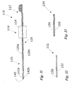
- FIG. 11 is a cross-section of the annular spacer region 130, the amplifier mounting section 114, and the output section 112 taken along line 11 - 11 of FIG. 10 .
- the second connecting region 126 and its associated signal paths 128a, 128b lead into a main body 140 of the spacer region 130.
- the main body 140 includes conductors 142a, 142b which extend entirely around the spacer region 130.
- the conductors 142a, 142b are attached to the signal paths 128a, 128b.
- the conductors 142a, 142b may be gold, copper, or any other conductive material.
- FIG. 12 is a cross-section of the diaphragm region 132 taken along line 12-12 of FIG. 10 .
- the diaphragm region 132 includes an annular-shaped main body 150 with a thin film diaphragm 152 located thereabove. While the periphery of the diaphragm 152 is attached to the main body 150, a substantial portion of the diaphragm 152 is exposed in the open region of the annular-shaped main body 150 so that it can move when subjected to sound.
- the diaphragm 152 is a flexible material like Mylar with a metallized surface for interacting with the charged plate in the charged backplate region 134.
- FIG. 13 is a cross-section of the charged backplate region 134 taken along line 13-13 in FIG. 10 .
- the charged backplate region 134 includes a main body 156 on which a charged layer 158 of material is placed.
- the charged layer 158 is located on the bottom of the main body 156.
- the material of the main body 134 is conductive, or may have a conductive layer.
- the charged layer 158 may be, for example, a Teflon® coating having a surface charge or a layer of electromagnetic film ("EMFi”) previously mentioned.
- the charged backplate region 134 can be a simple coating that is placed on the structure of the flex-print as shown in FIG. 13 . Alternatively, a separate structure having a charged surface can be placed onto a holding element within the charged backplate region 134 prior to the folding process.
- the main body 150 of the diaphragm region 132 receives the diaphragm 152.
- the diaphragm region 132 can be folded over at the first bridge 126, such that the diaphragm 152 comes into contact with the upper surface 146 of the internal conductor 142 in the spacer region 130. Because the diaphragm 152 has a metallized upper layer, the diaphragm 152 is in electrical contact with one of the conductors 142a around the entire periphery of the main body 140 of the spacer region 130.
- the charged backplate region 134 is folded under the spacer region 130, such that it comes into contact with the conductor 142b on the main body 140 of the spacer region 130. Consequently, the main body 140 of the spacer region 130 serves to maintain a known distance between the charged layer 158 and the diaphragm 152.
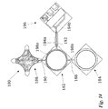
- FIG. 14 illustrates a transducing assembly 180 that, after being folded, will result in a cartridge that has a generally rectangular profile.
- the transducing assembly 180 includes a spacer region 182, a diaphragm region 184, and a charged backplate region 186.
- the spacer region 182 and the diaphragm region 184 are attached via a first bridge 188.
- the spacer region 182 and the charged backplate region 186 are attached via a second bridge 190.
- the spacer region 182 has an extending portion 192 that contains electrical leads 194a, 194b on either side of the extending portion 192 leading to an amplifier region 196.
- the electrical leads 194a, 194b are in contact with conductors 198a, 198b in the main body of the spacer region 182.
- the conductors 198a, 198b extend entirely around the spacer region 182, such that they are in contact with the diaphragm of the diaphragm region 184 and the backplate when they are folded over onto the spacer region 182.
- the charged backplate region 186 folds over onto the underside of the spacer region 182.
- the structure for the transducing assembly 180 is a flexible material, preferably flex-print. Again, all of the components can be assembled while the entire unfolded assembly 180 is horizontal.
- the charged backplate region 186 receives a charged backplate and the diaphragm region 184 receives a diaphragm onto the flex-print. Alternatively, the charged plate is produced by applying a layer of charged material.
- the transducing assembly 180 is a cartridge that is useful in any microphone or receiver.
- the extending portion 192 could be removed and a gold lead wire could be soldered or glued to an exposed surface of the internal conductor 198.
- this embodiment eliminates the need for an additional lead wire that would normally be soldered or glued to the cartridge, as is the case in many prior art electroacoustic transducers. Further, the transducing assembly 180 is much easier to manufacture than the prior art devices since the assembly is horizontal as the components are being attached thereto and is simply folded to result in the final cartridge.
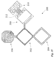
- FIG. 15 illustrates an alternative configuration that forms, when folded, another rectangular transducer 200, where the shape of the spacer region 202 and the diaphragm region 204 is rectangular.
- a backplate region 206 is substantially rectangular with the corners being truncated.
- the amplifier region 208 and the contact region 210 are connected by means of a bending region 212.
- FIG. 16 illustrates a cross-section of the resultant assembly, the cartridge 170, after the transducing region 116 of FIGS. 10-13 has been folded.
- the charged layer 158 of the backplate region 134 is directly exposed to the diaphragm 152 in the diaphragm region 132 through the opening of the annular-shaped spacer region 130 so that any movement of the diaphragm 152 relative to the charged layer 158 can be detected.
- the spacer region 130, the diaphragm region 132, and the charged backplate region 134 are secured to each other through a lamination process to develop the cartridge 170.
- the spacer region 130, the diaphragm region 132, and the charged backplate region 134 can be fixed in place through a clip or other type of fastener.
- FIG. 17 illustrates the further bending process of the fully integrated cartridge assembly 110 of FIGS. 10-13 that results in an assembly 110' that is of a shape suitable for packaging in a cylindrical microphone or receiver.
- the output section 112 has been folded, such that it now has a radius of curvature that is approximately the same as the radius of the periphery of the spacer region 130.
- the output terminals 122 can be located on either the inside or outside of the output section 112, but are preferably on the outside, as is shown in FIG. 11 .
- the first connecting region 118 is bent or folded so that the curved plane in which the output section 112 now resides is generally perpendicular to the plane of the amplifier mounting section 114.
- the integrated circuit 124 is on the underside of the amplifier mounting section 114.
- the second connecting region 126 is folded twice. The first fold is located adjacent to the amplifier mounting section 114 and the second fold is located adjacent to the spacer region 130. Because of the double fold of the second connecting region 126, the resultant cartridge 170 is in a plane that is generally parallel to the plane in which the amplifier mounting section 114 resides.
- the folding process is relatively easy and can be automated to produce the resultant cartridge 170 and the overall assembly 110' of FIG. 17 .
- the devices can be made in high volume and with high repeatability, and the dimensions of each section or subassembly can be very small with tight tolerance.
- the signal paths are buried within the flex-print material, it is very unlikely that there would be a breakage in those signal paths during the folding process.
- there is also no need for a soldering or gluing process whereby the cartridge 170 is electrically connected to the integrated circuit 124 via a lead wire.
- the assembly 110' can also undergo electrical testing at an earlier manufacturing stage, and cartridges having similar performances can be matched before assembly into a directional microphone.
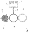
- FIG. 18 illustrates a variant of the spacer subassembly 52 of FIGS. 5-8 where a spacer subassembly 220 has a spacer region 222, a lead region 224, an amplifier region 226, and a contact region 228 all in a single plane, which are not to be folded for assembly.
- the entire transducer can be placed in a housing where the contact region 228 of the spacer subassembly 220 is exposed.
- the examples discussed thus far in FIGS. 1-18 have worked on the principle of the backplate being charged and the diaphragm including a thin metallization layer.
- the benefits achieved by this invention also apply to electroacoustic transducers which utilize a simple metallized backplate in conjunction with a charged diaphragm.
- the diaphragm may be the EMFi material that was previously mentioned.
- a conductor within the spacer member can be configured such that it contacts the backplate, rather than the diaphragm (or vice versa). Further, examples having one signal path can have multiple signal paths between the spacer and the electronics that process the signals (or vice versa).
- the cartridge can be made of three separate layers that are stacked and bonded in the final processing steps.
- the first layer of the group is the backplate layer with the charged material (e.g., charged Teflon®).
- the second layer is the spacer with the connecting portion with the signal path leading to the amplifier.
- the third layer is the diaphragm support layer with the diaphragm mounted.
- the resultant flex-print would have multiple distinct layers.
- the spacer is an electrical insulator, it may be possible to have the first and third layers be metal.
- the flex-print provides a location for mounting circuitry that is specifically used by the microphone
- circuitry that is used by other components of the listening device can be mounted on the flex-print.
- the flex-print serves as a platform for providing other hearing aid circuitry, such as signal processing.
Landscapes
- Physics & Mathematics (AREA)
- Engineering & Computer Science (AREA)
- Acoustics & Sound (AREA)
- Signal Processing (AREA)
- Electrostatic, Electromagnetic, Magneto- Strictive, And Variable-Resistance Transducers (AREA)
- Details Of Audible-Bandwidth Transducers (AREA)
Description
- This application claims the benefit of priority of
U.S. Provisional Patent Application No. 60/327,806, filed October 9, 2001 - This invention relates generally to electroacoustic transducers and, in particular, to an electroacoustic transducer having a flexible printed circuit board on which the internal components of the transducer are mounted.
- Electroacoustic transducers, which convert electrical energy into sound energy and vice versa, have been known for decades. They are useful for various purposes, including telecommunications equipment and hearing instruments, such as hearing aids (or generally "listening devices") that are located outside the ear or that fit within the ear canal. A conventional listening device includes a miniature microphone that receives acoustic waves and converts the acoustic waves to an audio signal. That audio signal is then processed (e.g., amplified) and sent to the receiver of the hearing aid or listening device. The receiver then converts the processed signal to an acoustic signal that is broadcast towards the eardrum.
- In addition to the size of the microphone becoming smaller, the amount of electronic equipment fitted with a microphone is rapidly growing. For many applications, including telecommunications equipment and hearing instruments, there is a demand for low cost, high performance miniature microphones.
- The state-of-the-art transducer type used for these applications is the electret microphone. Generally, the construction of the electret microphone consists of three parts: a microphone housing, an impedance conversion circuit, and the microphone cartridge. Such a cartridge typically consists of a rigid plate ("backplate") and a metallized polymer diaphragm separated by a thin spacer. The diaphragm and the backplate form the plates of a variable capacitor. A dielectric layer in either the backplatc or diaphragm is permanently electrically charged ("electret"). An incoming sound wave causes the diaphragm to move relative to the backplate, resulting in a capacitance change. The change in capacitance alters the electrical field strength from the fixed charge and, thus, causes a voltage change across the capacitor.
- Because the capacitance between the backplate and diaphragm is very small, the impedance of the electrical signal source is very high, and the signal is very sensitive to interference. Therefore, electret microphones typically include an internal buffer amplifier (or impedance conversion circuit). Both the backplate and the diaphragm of the cartridge must be connected with the buffer amplifier. Generally, either the backplate or the diaphragm ("reference") is connected with the amplifier via the microphone housing. The other ("signal") is connected with the amplifier by a wire, which requires the use of a soldering process and/or a small drop of electrically conductive adhesive. This is often a manual step subject to human error and is time consuming.
- Prior art may be seen in
US 5 881 158 andEP 0 499 237 . - As such, a need exists for a new type of electroacoustic transducer that is easier to manufacture and requires less parts.
- The present invention solves the aforementioned problems. In one embodiment, the present invention involves a novel method and structure in which a flexible printed circuit board ("flex-print") serves two functions: separating the diaphragm and backplate, and electrically connecting the cartridge and the buffer amplifier. Thus, the flex-print includes a spacer portion that maintains the appropriate distance between the diaphragm and the backplate, and an integral lead portion having an electrical conductor that serves as the signal path for transmitting the electrical signal from the cartridge to the buffer amplifier. The spacer portion has an electrical conductor that is electrically coupled to the diaphragm or backplate and the electrical conductor of the integral lead portion. Thus, the integral lead portion eliminates the need for soldering or gluing a lead wire between the two components.
- The integral lead portion of the flex-print may optionally include a second electrical conductor that provides the reference path from the cartridge to the amplifier. When this embodiment is used, the microphone housing is not needed to provide the reference path to the buffer amplifier.
- Further, the flex-print may also be used as the carrier for the buffer amplifier and its associated circuitry. In this embodiment, the flex-print includes another mounting section for the buffer amplifier and its associated circuitry. Thus, the integral lead portion has the spacer portion at one end and the amplifier mounting section on the other end. Generally, the buffer amplifier is a small integrated semiconductor circuit that is connected with the leads by bonding wires. Elements not integrated with the semiconductor, e.g., resistors and capacitors, can also be surface mounted on the flex-print by using SMD components. Alternatively, the flip-chip technology can be used for the buffer amplifier.
- In a further embodiment, the flex-print may also be used as a portion of the diaphragm subassembly. The diaphragm is a metallized polymer film that is stretched in a ring-shaped or rectangular frame. While this frame can be made of a separate piece of flex-print, the frame can also be made from the same piece of flex-print that is used for the spacer and its integral lead portion. As such, the flex-print includes a region for mounting the diaphragm film that is eventually folded over the spacer portion of the flex-print.
- A similar configuration can be made with respect to the backplate subassembly. The backplate subassembly includes a rigid plate with a conductive portion and a charged layer. The rigid plate can be made from flex-print material. Thus, the rigid plate can also be manufactured from the same piece of flex-print as was used for the spacer. A dielectric film can be laminated on top of the backplate to provide for storage of a permanent electrical charge.
- In yet a further alternative of the invention, all of the components of the cartridge are manufactured and assembled on the same piece of flex-print. As such, the flex-print includes a region for mounting the moveable diaphragm. The backplate is located on another part of the flex-print. A spacer element is made from another part of the flex-print and maintains a certain spacing between the moveable diaphragm and the backplate after folding the flex-print. The spacer element has an internally conductive element(s) leading to and being in electrical contact with the backplate and/or the moveable diaphragm. The spacer element includes an integral lead portion made of the flex-print that includes a signal path for transmitting the electrical signal to the buffer amplifier, which can be located on yet another portion of the flex-print.
- Because of the flexibility of the flex-print, the manufacturing process of the assembly can be performed while it is in a horizontal plane. After all of the components are attached to the flex-print, it can be folded or bent to a predetermined orientation so as to fit within a housing of a microphone or receiver.
- The above summary of the present invention is not intended to represent each embodiment or every aspect of the present invention. This is the purpose of the Figures and the detailed description which follow.
-
-
FIG. 1 is a cross-sectional view of a flexible printed circuit board with a single-side metallization layer in a first embodiment of the present invention. -
FIG. 2 is a top view of the unfolded flexible printed circuit board ofFIG. 1 . -
FIG. 3 is a cross-sectional view of the unfolded flexible printed circuit board taken along line 3-3 ofFIG. 2 . -
FIG. 4 is a cross-sectional view of a flexible printed circuit board with a single side metallization layer in a second embodiment of the present invention. -
FIG. 5 is a cross-sectional view of a double-sided metallized flexible printed circuit board assembly illustrating a third embodiment of the present invention. -
FIG. 6 is a top view of the unfolded flexible printed circuit board ofFIG. 5 . -
FIG. 7 is a cross-sectional view of the unfolded flexible printed circuit board taken along line 7-7 ofFIG. 6 . -
FIG. 8 is a bottom view of the unfolded flexible printed circuit board ofFIG. 5 . -
FIG. 9 is a top view of an unfolded printed circuit board assembly that, when folded, becomes a fully integrated microphone cartridge assembly according to another embodiment of the present invention. -
FIG. 10 is a top view of an unfolded printed circuit board assembly, similar to that ofFIG. 9 , incorporating another embodiment of the present invention. -
FIG. 11 is a cross-sectional view of the unfolded flexible printed circuit board taken along line 11-11 ofFIG. 10 . -
FIG. 12 is a cross-sectional view of the diaphragm region taken along line 12-12 ofFIG. 10 . -
FIG. 13 is a cross-sectional view of the charged plate region taken along line 13-13 ofFIG. 10 . -
FIG 14 is a top plan view of an alternative cartridge that has a rectangular-shaped outline. -
FIG 15 is a top plan view of an alternative cartridge that has a rectangular-shaped outline and diaphragm. -
FIG. 16 is an assembly view of the cartridge of the present invention. -
FIG. 17 is an isometric view of the present invention ofFIG. 10 after full assembly such that its shape will accommodate its placement in a cylindrical microphone or receiver. -
FIG. 18 is a top plan view of a flat flexible printed circuit board. - While the invention is susceptible to various modifications and alternative forms, specific embodiments have been shown by way of example in the drawings and will be described in detail herein. It should be understood, however, that the invention is not intended to be limited to the particular forms disclosed. Rather, the invention is to cover all modifications, equivalents, and alternatives falling within the spirit and scope of the invention as defined by the appended claims.
-
FIG. 1 illustrates amicrophone cartridge 10 having aspacer subassembly 12 made of a flexible printed circuit board material, i.e., flex-print. Thespacer subassembly 12, which has an annularshape spacing section 13, separates adiaphragm subassembly 14 from abackplate subassembly 16. The flex-print (e.g., polyimide) can have a thickness in the range of 25 to 50 microns, which is about the size of separation that is needed between thediaphragm subassembly 14 and thebackplate subassembly 16. Thediaphragm subassembly 14 includes a thin, moveable metallized (polymer)diaphragm 18 that is mounted on aframe 20. Thebackplate assembly 16 includes arigid base layer 22 and a chargeddielectric layer 24, which may be a Teflon® coating having a surface charge or a layer of special electret film ("EMFi"), such as one disclosed inU.S. Patent Nos. 4,654,546 and5,757,090 to Kirjavinen. In essence, thespacer subassembly 12 maintains the appropriate spacing between the metallizeddiaphragm 18 and the chargedlayer 24 after thediaphragm subassembly 14 and thebackplate subassembly 16 have been stacked on thespacer subassembly 12. The flex-print spacer subassembly 12 has an exposed, annular metal trace 26 (FIG. 2 ) on one side of thespacer subassembly 12 and asignal path 28 on anintegral lead portion 29. Themetal trace 26, which is connected to thesignal path 28, is in electrical contact with thediaphragm 18. -
FIGS. 2 and 3 show a top view and a cross-sectional view of the unfoldedspacer subassembly 12, with the cross-section inFIG. 3 being taken along line 3-3 inFIG. 2 . In addition,FIGS. 2 and 3 illustrate the connection of theintegral lead portion 29 to a small circuit board, which is anamplifier portion 32 of thespacer subassembly 12. Thesignal path 28 of theintegral lead portion 29 electrically transmits the electric signal from thediaphragm 18 to abuffer amplifier 30 on theamplifier portion 32. Thebackplate 16 provides the reference voltage and is connected with thereference terminal 36 of thebuffer amplifier 30 via the metal housing of the microphone (not shown). - In the example of
FIGS. 1-3 , theamplifier portion 32 of thespacer subassembly 12 has threeoutput terminals 34 that transmit the output signal from thebuffer amplifier 30 and provide the supply voltage. Thus, theamplifier portion 32 on which thebuffer amplifier 30 is mounted is made from the same flex-print material as the spacingportion 13 and theintegral lead portion 29 of thespacer subassembly 12. Theintegral lead portion 29 and its associatedsignal path 28, however, can terminate before thebuffer amplifier 30. In this latter case, theintegral lead portion 29 has a simple terminal at the end of thesignal path 28 that can be used for connection to thebuffer amplifier 30, which is mounted on a different structure. -
FIG. 4 shows an alternative cartridge 10' where the positions of thediaphragm subassembly 14 and thebackplate subassembly 16 have been swapped. Thesignal path 28 at abend region 32 of the integral lead portion 29 (after it transitions from the flat shape ofFIGS. 2 and 3 to the folded shape ofFIG. 4 ) is held on the conductive base layer 22' of thebackplate subassembly 16 by a drop of conductive adhesive 35 that makes an electrical connection with thebase layer 22. The alternative ofFIG. 4 with theconductive adhesive 34 is useful since the charged layer 24' is non conductive. - In the example of
FIGS. 5-8 , acartridge 50 includes aspacer subassembly 52 that is made of a flexible material, such as flex-print, havingmetal traces double traces backplate subassembly 54 and adiaphragm subassembly 56 to a buffer amplifier 60 (not shown inFIG. 5 ). Thus, anintegral lead portion 62 has a first signal path 64 (bottom view inFIG. 8 ) on one of its sides and a second signal path 66 (top view ofFIG. 6 ) on the other of its sides. Themetal trace 66 makes contact with thebackplate subassembly 54 throughconductive adhesive 67. The metallization pattern of theamplifier region 68 of thespacer subassembly 52 provides all required connections for the semi-conductor circuit. Additionally, passive components may be mounted on theamplifier region 68 of thespacer subassembly 52. The embodiment ofFIGS. 5-8 alleviates the need to use metal housing to provide the reference connection between thecartridge 50 and thebuffer amplifier 60 as was done by use of thereference terminal 36 inFIG. 2 . - It should be further noted that use of the flex-print provides for the opportunity of passive or active shielding. Conductive layers or conductive wires can be on the same layer or adjacent layers as the signal paths. Thus, these paths can be shielded from exposure to electromagnetic energy and thereby provide a cleaner output signal.
- Furthermore, the
cartridges cartridges cartridges - The embodiments discussed thus far in
FIGS. 1-8 have worked on the principle of the backplate being charged and the diaphragm including a thin metallization layer. The benefits achieved by this invention, however, also apply to electroacoustic transducers which utilize a simple metallized backplate in conjunction with a charged diaphragm. As an example, the diaphragm may be made from the EMFi material that was previously mentioned. This use of the flex-print for mounting components and separating components in a microphone is also applicable to non-electret type capacitive transducers. While the illustrated embodiments are directed to electret microphones, the flex-print concept is also applicable for non-electret condenser microphones and for miniature electrostatic loudspeakers. -
FIG. 9 illustrates an unfoldedcartridge assembly 70 made of a flexible material, such as flex-print. Thecartridge assembly 70 includes aspacer portion 72, anintegral lead portion 74 having two signal paths, anamplifier portion 76 on which a buffer amplifier 77 (and its associate components) is mounted, a diaphragm mounting portion 78 (shown with a diaphragm thereon), and abackplate mounting portion 79. Thus, thecartridge assembly 70 is a backplate carrier and a diaphragm carrier, making it a fully integrated microphone component. During the production process, all parts are assembled on the unfoldedcartridge assembly 70. Thebackplate mounting portion 79 and thediaphragm mounting portion 78 are then folded towards thespacer portion 72. Thespacer portion 72 may include a single exposed metal trace for making contact with either the diaphragm or backplate, or two metal traces making contact with both the diaphragm and backplate. An embodiment similar toFIG. 9 is discussed in more detail below with respect toFIGS. 10-13 . In particular, the folding processes that would be used with thecartridge assembly 70 arc described in detail below. - Referring to
FIG. 10 , a fully integratedcartridge assembly 110 that is useful in a microphone (including directional microphones) is illustrated. Theassembly 110 includes anoutput section 112, anamplifier mounting section 114, and atransducing section 116. Theoutput section 112 and theamplifier mounting section 114 are attached to each other via a first connectingregion 118. The first connectingregion 118 serves as a conduit foroutput signal paths 120 that connectoutput terminals 122 to anintegrated circuit 124 which, as shown inFIG. 10 , is an amplifier. Theamplifier mounting section 114 and thetransducing section 116 are attached via a second connectingregion 126. The secondconnecting region 126 also has a signal path 128 leading from theintegrated circuit 124 to thetransducing section 116. Thesignal paths 120, 128 can be made of gold, copper, or any other conductive material. - Simply stated, after assembly, the
transducing section 116 receives sound and converts (i.e., transduces) the sound signal into a raw audio signal. Theamplifier mounting section 114 receives the raw audio signal from thetransducing section 116 and amplifies that signal. Finally, the amplified signal from theamplifier mounting section 114 is sent to theoutput section 112 where it can be communicated via theoutput terminals 122. - The
transducing section 116 has three distinct regions. Aspacer region 130 is located in the central portion of thetransducing section 116. Above thespacer region 130 is adiaphragm region 132, and below thespacer region 130 is a chargedbackplate region 134. Thespacer region 130 is connected to thediaphragm region 132 via afirst bridge 136. Likewise, thespacer region 130 is connected to the chargedbackplate region 134 via asecond bridge 138. As shown, theassembly 110 ofFIG. 10 is in an assembled form before any bending that ultimately results in the folded assembly, such as the one shown inFIG. 16 . - The
output section 112, theamplifier mounting section 114, and thetransducing section 116 arc preferably made of a flex-print constructed out of a flexible material, like polyimide. Such a construction allows for the passing of conductive leads within the material that define theoutput section 112, theamplifier mounting section 114, and thetransducing section 116. Because it is thin and flexible, theassembly 110 can be folded or bent into a variety of shapes without disrupting the internally conductive elements within the material. - As mentioned above, the use of a flex-print provides for the opportunity of passive or active shielding. Conductive layers or conductive wires can be on the same layer or adjacent layers as the signal paths. Thus, these paths can be shielded from exposure to electromagnetic energy and thereby provide a cleaner output signal.
-
FIG. 11 is a cross-section of theannular spacer region 130, theamplifier mounting section 114, and theoutput section 112 taken along line 11 - 11 ofFIG. 10 . As can be seen, the second connectingregion 126 and its associatedsignal paths main body 140 of thespacer region 130. Themain body 140 includesconductors spacer region 130. Theconductors signal paths conductors -
FIG. 12 is a cross-section of thediaphragm region 132 taken along line 12-12 ofFIG. 10 . Thediaphragm region 132 includes an annular-shapedmain body 150 with athin film diaphragm 152 located thereabove. While the periphery of thediaphragm 152 is attached to themain body 150, a substantial portion of thediaphragm 152 is exposed in the open region of the annular-shapedmain body 150 so that it can move when subjected to sound. In the illustrated embodiment, thediaphragm 152 is a flexible material like Mylar with a metallized surface for interacting with the charged plate in the chargedbackplate region 134. -
FIG. 13 is a cross-section of the chargedbackplate region 134 taken along line 13-13 inFIG. 10 . The chargedbackplate region 134 includes amain body 156 on which a chargedlayer 158 of material is placed. The chargedlayer 158 is located on the bottom of themain body 156. The material of themain body 134 is conductive, or may have a conductive layer. The chargedlayer 158 may be, for example, a Teflon® coating having a surface charge or a layer of electromagnetic film ("EMFi") previously mentioned. The chargedbackplate region 134 can be a simple coating that is placed on the structure of the flex-print as shown inFIG. 13 . Alternatively, a separate structure having a charged surface can be placed onto a holding element within the chargedbackplate region 134 prior to the folding process. - During assembly, the
main body 150 of thediaphragm region 132 receives thediaphragm 152. Once thediaphragm 152 is attached to themain body 150, thediaphragm region 132 can be folded over at thefirst bridge 126, such that thediaphragm 152 comes into contact with the upper surface 146 of the internal conductor 142 in thespacer region 130. Because thediaphragm 152 has a metallized upper layer, thediaphragm 152 is in electrical contact with one of theconductors 142a around the entire periphery of themain body 140 of thespacer region 130. Next, after receiving the coating or film to produce a charge, the chargedbackplate region 134 is folded under thespacer region 130, such that it comes into contact with theconductor 142b on themain body 140 of thespacer region 130. Consequently, themain body 140 of thespacer region 130 serves to maintain a known distance between the chargedlayer 158 and thediaphragm 152. -
FIG. 14 illustrates a transducingassembly 180 that, after being folded, will result in a cartridge that has a generally rectangular profile. The transducingassembly 180 includes aspacer region 182, adiaphragm region 184, and a chargedbackplate region 186. Thespacer region 182 and thediaphragm region 184 are attached via afirst bridge 188. Likewise, thespacer region 182 and the chargedbackplate region 186 are attached via asecond bridge 190. Thespacer region 182 has an extendingportion 192 that containselectrical leads portion 192 leading to anamplifier region 196. Theelectrical leads conductors spacer region 182. Theconductors spacer region 182, such that they are in contact with the diaphragm of thediaphragm region 184 and the backplate when they are folded over onto thespacer region 182. As with the previous embodiment, the chargedbackplate region 186 folds over onto the underside of thespacer region 182. - Like the previous embodiment, the structure for the transducing
assembly 180 is a flexible material, preferably flex-print. Again, all of the components can be assembled while the entire unfoldedassembly 180 is horizontal. The chargedbackplate region 186 receives a charged backplate and thediaphragm region 184 receives a diaphragm onto the flex-print. Alternatively, the charged plate is produced by applying a layer of charged material. Once the transducingassembly 180 has been properly folded, the transducingassembly 180 is a cartridge that is useful in any microphone or receiver. Although not ideal, the extendingportion 192 could be removed and a gold lead wire could be soldered or glued to an exposed surface of the internal conductor 198. As with the previous embodiment, this embodiment eliminates the need for an additional lead wire that would normally be soldered or glued to the cartridge, as is the case in many prior art electroacoustic transducers. Further, the transducingassembly 180 is much easier to manufacture than the prior art devices since the assembly is horizontal as the components are being attached thereto and is simply folded to result in the final cartridge. -
FIG. 15 illustrates an alternative configuration that forms, when folded, anotherrectangular transducer 200, where the shape of thespacer region 202 and thediaphragm region 204 is rectangular. Abackplate region 206 is substantially rectangular with the corners being truncated. Also, theamplifier region 208 and thecontact region 210 are connected by means of abending region 212. -
FIG. 16 illustrates a cross-section of the resultant assembly, thecartridge 170, after thetransducing region 116 ofFIGS. 10-13 has been folded. The chargedlayer 158 of thebackplate region 134 is directly exposed to thediaphragm 152 in thediaphragm region 132 through the opening of the annular-shapedspacer region 130 so that any movement of thediaphragm 152 relative to the chargedlayer 158 can be detected. Once the folding process has been completed, thespacer region 130, thediaphragm region 132, and the chargedbackplate region 134 are secured to each other through a lamination process to develop thecartridge 170. Alternatively, thespacer region 130, thediaphragm region 132, and the chargedbackplate region 134 can be fixed in place through a clip or other type of fastener. -
FIG. 17 illustrates the further bending process of the fully integratedcartridge assembly 110 ofFIGS. 10-13 that results in an assembly 110' that is of a shape suitable for packaging in a cylindrical microphone or receiver. Here, theoutput section 112 has been folded, such that it now has a radius of curvature that is approximately the same as the radius of the periphery of thespacer region 130. Theoutput terminals 122 can be located on either the inside or outside of theoutput section 112, but are preferably on the outside, as is shown inFIG. 11 . The first connectingregion 118 is bent or folded so that the curved plane in which theoutput section 112 now resides is generally perpendicular to the plane of theamplifier mounting section 114. Theintegrated circuit 124 is on the underside of theamplifier mounting section 114. The secondconnecting region 126 is folded twice. The first fold is located adjacent to theamplifier mounting section 114 and the second fold is located adjacent to thespacer region 130. Because of the double fold of the second connectingregion 126, theresultant cartridge 170 is in a plane that is generally parallel to the plane in which theamplifier mounting section 114 resides. - Because the fully integrated
cartridge assembly 110 ofFIGS. 10-13 has been built upon a flex-print, the folding process is relatively easy and can be automated to produce theresultant cartridge 170 and the overall assembly 110' ofFIG. 17 . Because of the use of the flex-print, the devices can be made in high volume and with high repeatability, and the dimensions of each section or subassembly can be very small with tight tolerance. Further, because the signal paths are buried within the flex-print material, it is very unlikely that there would be a breakage in those signal paths during the folding process. Compared with prior art transducers, there is also no need for a soldering or gluing process whereby thecartridge 170 is electrically connected to theintegrated circuit 124 via a lead wire. This also reduces the number of parts for manufacturing since the lead wire, the glue, and the soldering material arc not needed. Furthermore, as mentioned above, the assembly 110' can also undergo electrical testing at an earlier manufacturing stage, and cartridges having similar performances can be matched before assembly into a directional microphone. -
FIG. 18 illustrates a variant of thespacer subassembly 52 ofFIGS. 5-8 where aspacer subassembly 220 has aspacer region 222, alead region 224, anamplifier region 226, and acontact region 228 all in a single plane, which are not to be folded for assembly. After attachment of a backplate assembly and a diaphragm assembly, the entire transducer can be placed in a housing where thecontact region 228 of thespacer subassembly 220 is exposed. - The examples discussed thus far in
FIGS. 1-18 have worked on the principle of the backplate being charged and the diaphragm including a thin metallization layer. The benefits achieved by this invention, however, also apply to electroacoustic transducers which utilize a simple metallized backplate in conjunction with a charged diaphragm. As an example, the diaphragm may be the EMFi material that was previously mentioned. - In each of the examples, as previously mentioned, a conductor within the spacer member can be configured such that it contacts the backplate, rather than the diaphragm (or vice versa). Further, examples having one signal path can have multiple signal paths between the spacer and the electronics that process the signals (or vice versa).
- In an alternative example of
FIGS. 14 and15 that is similar toFIGS. 1-8 , the cartridge can be made of three separate layers that are stacked and bonded in the final processing steps. The first layer of the group is the backplate layer with the charged material (e.g., charged Teflon®). The second layer is the spacer with the connecting portion with the signal path leading to the amplifier. The third layer is the diaphragm support layer with the diaphragm mounted. Thus, the resultant flex-print would have multiple distinct layers. And, since the spacer is an electrical insulator, it may be possible to have the first and third layers be metal. - Furthermore, in addition to the flex-print providing a location for mounting circuitry that is specifically used by the microphone, circuitry that is used by other components of the listening device can be mounted on the flex-print. Thus, the flex-print serves as a platform for providing other hearing aid circuitry, such as signal processing.
Claims (15)
- An assembly (10, 10', 50, 70, 110, 180, 200) for transducing sound into an electrical signal, comprising:a moveable diaphragm (18, 56, 78, 132, 152, 184, 204) having a first surface;a backplate (16, 24, 24', 54, 79, 134, 186, 206) having a second surface opposing said first surface; anda flexible printed circuit board having a spacer element (12, 52, 72, 130, 182, 202, 220) for maintaining a certain spacing between said moveable diaphragm and said backplate, said flexible printed circuit board having an integral conductive element leading to and being in electrical contact with at least one of said backplate and said moveable diaphragm, CHARACTERIZED in that said integral conductive element includes an exposed trace in electrical contact with said at least one of said backplate and said moveable diaphragm, said spacer further including an integral lead portion (29, 62, 74, 128, 194, 224) for transmitting a signal from said at least one of said backplate and said moveable diaphragm to another electrical component (30, 32, 60, 124, 208, 226) in said assembly.
- The assembly of claim 1, wherein said another electrical component is an amplifier mounted on an amplifier region of said flexible printed circuit board, said integral lead portion being between said amplifier region and said spacer.
- The assembly of claims 1-2, wherein said flexible printed circuit board has a thickness in the range of from about 25 to about 50 microns.
- The assembly of claims 1-2, wherein said spacer has an annular shape with a rectangular or circular periphery.
- The microphone subassembly of claim 4, wherein said exposed electrical trace is located completely around said annular shape.
- The assembly of claim 1, wherein said diaphragm is mounted on a diaphragm carrier (20) made of a printed circuit board material.
- The assembly of claim 6, wherein said printed circuit board material of said diaphragm carrier (20) is integral with said flexible printed circuit board of said spacer, said diaphragm carrier being folded over onto said spacer during assembly.
- The assembly of claim 1, wherein said backplate is comprised of at least a base layer (22, 22') and a charged layer (24), said base layer being made of a printed circuit board material.
- The assembly of claim 8, wherein said printed circuit board material of said base layer is integral with said printed circuit board material of said spacer, said base layer carrier being folded over onto said spacer during assembly.
- The assembly of claim 1, wherein said assembly is acoustically and electrically testable before assembly into a microphone housing.
- A method of making a microphone cartridge (10, 10', 50, 70, 110, 180, 200), comprising:providing a moveable diaphragm (18, 56, 57, 78, 132, 152, 184, 204);providing a backplate (16, 24, 24', 54, 79, 134, 186, 206);providing a flexible circuit board material having an integral conductive element and a spacer element (12, 52, 72, 130, 182, 202, 220) having an annular portion; andstacking said moveable diaphragm and said backplate on said annular portion, so that the integral conductive element leads to and is in electrical contact with at least one of said backplate and said moveable diaphragm, CHARACTERIZED in that said flexible printed circuit board includes an exposed conductive trace for contacting at least one of said diaphragm and said backplate, said spacer further including an integral lead portion 29, 62, 74, 128, 194, 224) for transmitting a signal from said at least one of said backplate and said moveable diaphragm to another electrical component (30, 32, 60, 124, 208, 226) in said microphone.
- The method of claim 11, wherein said flexible printed circuit board includes a region for mounting an amplifier.
- The method of claim 11, wherein said stacking includes folding said moveable diaphragm and said backplate on said flexible printed circuit board.
- The assembly of claim 1, wherein said another electrical component includes an amplifier.
- The assembly of claim 1, wherein said assembly is housed within a directional microphone.
Applications Claiming Priority (2)
| Application Number | Priority Date | Filing Date | Title |
|---|---|---|---|
| US32780601P | 2001-10-09 | 2001-10-09 | |
| US327806P | 2001-10-09 |
Publications (3)
| Publication Number | Publication Date |
|---|---|
| EP1303164A2 EP1303164A2 (en) | 2003-04-16 |
| EP1303164A3 EP1303164A3 (en) | 2006-08-16 |
| EP1303164B1 true EP1303164B1 (en) | 2014-01-22 |
Family
ID=23278146
Family Applications (1)
| Application Number | Title | Priority Date | Filing Date |
|---|---|---|---|
| EP02079187.7A Expired - Lifetime EP1303164B1 (en) | 2001-10-09 | 2002-10-09 | Microphone having a flexible printed circuit board for mounting components |
Country Status (3)
| Country | Link |
|---|---|
| US (1) | US7239714B2 (en) |
| EP (1) | EP1303164B1 (en) |
| DK (1) | DK1303164T3 (en) |
Families Citing this family (108)
| Publication number | Priority date | Publication date | Assignee | Title |
|---|---|---|---|---|
| US7361338B2 (en) * | 1999-10-05 | 2008-04-22 | Agensys, Inc. | Methods to inhibit growth of prostate cancer cells |
| EP1623601A1 (en) * | 2003-04-28 | 2006-02-08 | Knowles Electronics, LLC | Method and apparatus for substantially improving power supply rejection performance in a miniature microphone assembly |
| WO2005032212A1 (en) * | 2003-09-29 | 2005-04-07 | Bang & Olufsen Medicom A/S | A microphone component and a method for its manufacture |
| DK1767051T3 (en) * | 2004-07-09 | 2013-06-24 | Knowles Electronics Llc | Apparatus for suppressing radio frequency interference in a preamplifier microphone device |
| JP2008028946A (en) * | 2006-07-25 | 2008-02-07 | Star Micronics Co Ltd | Condenser microphone |
| US8000491B2 (en) * | 2006-10-24 | 2011-08-16 | Nokia Corporation | Transducer device and assembly |
| DE102007014579B4 (en) * | 2007-03-23 | 2009-05-07 | Sennheiser Electronic Gmbh & Co. Kg | microphone |
| DE102007025589A1 (en) * | 2007-05-31 | 2008-12-11 | Sennheiser Electronic Gmbh & Co. Kg | Headphones and headset |
| US8135163B2 (en) * | 2007-08-30 | 2012-03-13 | Klipsch Group, Inc. | Balanced armature with acoustic low pass filter |
| US8184833B2 (en) * | 2007-12-14 | 2012-05-22 | Sony Ericsson Mobile Communications Ab | Electrostatic speaker arrangement for a mobile device |
| DE102008013395B4 (en) * | 2008-03-10 | 2013-10-10 | Sennheiser Electronic Gmbh & Co. Kg | condenser microphone |
| US7901145B2 (en) * | 2008-03-14 | 2011-03-08 | Finisar Corporation | Mini optical subassembly |
| KR100970197B1 (en) * | 2008-07-11 | 2010-07-14 | 주식회사 비에스이 | Variable directional microphone assembly and method of manufacturing the same |
| KR100963296B1 (en) | 2008-07-11 | 2010-06-11 | 주식회사 비에스이 | Variable directional microphone assembly and method of manufacturing the same |
| DE102009018884A1 (en) * | 2009-04-24 | 2010-08-26 | Siemens Medical Instruments Pte. Ltd. | Earpiece for use in e.g. hearing device for hearing impaired person, has flexible printed board provided with outer- and inner contacts, which are electrically connected with each other in pairs |
| WO2011087770A2 (en) * | 2009-12-22 | 2011-07-21 | Mh Acoustics, Llc | Surface-mounted microphone arrays on flexible printed circuit boards |
| US9357287B2 (en) | 2011-07-07 | 2016-05-31 | Sonion Nederland B.V. | Multiple receiver assembly and a method for assembly thereof |
| DK2723102T3 (en) | 2012-10-18 | 2019-01-02 | Sonion Nederland Bv | Transducer, transducer hearing aid and a method of operating the transducer |
| DK2723098T3 (en) | 2012-10-18 | 2017-03-13 | Sonion Nederland Bv | Double transducer with common membrane |
| US9807525B2 (en) | 2012-12-21 | 2017-10-31 | Sonion Nederland B.V. | RIC assembly with thuras tube |
| EP2750413B1 (en) | 2012-12-28 | 2017-02-22 | Sonion Nederland B.V. | Hearing aid device |
| US9401575B2 (en) | 2013-05-29 | 2016-07-26 | Sonion Nederland Bv | Method of assembling a transducer assembly |
| EP2849463B1 (en) | 2013-09-16 | 2018-04-04 | Sonion Nederland B.V. | A transducer comprising moisture transporting element |
| DK3550852T3 (en) | 2014-02-14 | 2021-02-01 | Sonion Nederland Bv | A joiner for a receiver assembly |
| EP2908559B1 (en) | 2014-02-18 | 2016-10-05 | Sonion A/S | A method of manufacturing assemblies for hearing aids |
| DK2914018T3 (en) | 2014-02-26 | 2017-01-30 | Sonion Nederland Bv | Speaker, luminaire and method |
| US9432774B2 (en) | 2014-04-02 | 2016-08-30 | Sonion Nederland B.V. | Transducer with a bent armature |
| EP2953380A1 (en) | 2014-06-04 | 2015-12-09 | Sonion Nederland B.V. | Acoustical crosstalk compensation |
| US9729974B2 (en) | 2014-12-30 | 2017-08-08 | Sonion Nederland B.V. | Hybrid receiver module |
| EP3051841B1 (en) | 2015-01-30 | 2020-10-07 | Sonion Nederland B.V. | A receiver having a suspended motor assembly |
| EP3057339B1 (en) | 2015-02-10 | 2020-09-23 | Sonion Nederland B.V. | Microphone module with shared middle sound inlet arrangement |
| US9980029B2 (en) | 2015-03-25 | 2018-05-22 | Sonion Nederland B.V. | Receiver-in-canal assembly comprising a diaphragm and a cable connection |
| DK3073764T3 (en) | 2015-03-25 | 2021-05-10 | Sonion Nederland Bv | A hearing aid comprising an insert member |
| US9565493B2 (en) | 2015-04-30 | 2017-02-07 | Shure Acquisition Holdings, Inc. | Array microphone system and method of assembling the same |
| US9554207B2 (en) | 2015-04-30 | 2017-01-24 | Shure Acquisition Holdings, Inc. | Offset cartridge microphones |
| DK3133829T3 (en) | 2015-08-19 | 2020-06-22 | Sonion Nederland Bv | AUDIO UNIT WITH IMPROVED FREQUENCY RESPONSE |
| US10433077B2 (en) | 2015-09-02 | 2019-10-01 | Sonion Nederland B.V. | Augmented hearing device |
| US9668065B2 (en) | 2015-09-18 | 2017-05-30 | Sonion Nederland B.V. | Acoustical module with acoustical filter |
| US10021494B2 (en) | 2015-10-14 | 2018-07-10 | Sonion Nederland B.V. | Hearing device with vibration sensitive transducer |
| DK3160157T3 (en) | 2015-10-21 | 2018-12-17 | Sonion Nederland Bv | Vibration-compensated vibroacoustic device |
| US10582303B2 (en) | 2015-12-04 | 2020-03-03 | Sonion Nederland B.V. | Balanced armature receiver with bi-stable balanced armature |
| EP3185584B1 (en) | 2015-12-21 | 2020-04-22 | Sonion Nederland B.V. | Receiver assembly having a distinct longitudinal direction |
| US9866959B2 (en) | 2016-01-25 | 2018-01-09 | Sonion Nederland B.V. | Self-biasing output booster amplifier and use thereof |
| EP3200479A3 (en) | 2016-01-28 | 2017-08-30 | Sonion Nederland B.V. | An assembly comprising an electrostatic sound generator and a transformer |
| US10194248B2 (en) | 2016-02-19 | 2019-01-29 | Apple Inc. | Speaker with flex circuit acoustic radiator |
| DK3232685T3 (en) | 2016-04-13 | 2021-04-19 | Sonion Nederland Bv | A dome for a personal audio device |
| US10078097B2 (en) | 2016-06-01 | 2018-09-18 | Sonion Nederland B.V. | Vibration or acceleration sensor applying squeeze film damping |
| EP3501185A4 (en) * | 2016-08-18 | 2020-03-18 | Harman International Industries, Incorporated | ELECTRIC CONDENSER MICROPHONE AND MANUFACTURING METHOD THEREFOR |
| DK3703389T1 (en) | 2016-08-26 | 2020-11-09 | Sonion Nederland Bv | Vibration sensor with low-frequency roll-off response curve |
| EP3293985B1 (en) | 2016-09-12 | 2021-03-24 | Sonion Nederland B.V. | Receiver with integrated membrane movement detection |
| US10321235B2 (en) | 2016-09-23 | 2019-06-11 | Apple Inc. | Transducer having a conductive suspension member |
| EP3313097B1 (en) | 2016-10-19 | 2020-08-26 | Sonion Nederland B.V. | An ear bud or dome |
| EP3324649A1 (en) | 2016-11-18 | 2018-05-23 | Sonion Nederland B.V. | A transducer with a high sensitivity |
| US10327072B2 (en) | 2016-11-18 | 2019-06-18 | Sonion Nederland B.V. | Phase correcting system and a phase correctable transducer system |
| EP3324538A1 (en) | 2016-11-18 | 2018-05-23 | Sonion Nederland B.V. | A sensing circuit comprising an amplifying circuit |
| US20180145643A1 (en) | 2016-11-18 | 2018-05-24 | Sonion Nederland B.V. | Circuit for providing a high and a low impedance and a system comprising the circuit |
| DK3337184T3 (en) | 2016-12-14 | 2020-06-02 | Sonion Nederland Bv | An armature and a transducer comprising the armature |
| EP3337191B1 (en) | 2016-12-16 | 2021-05-19 | Sonion Nederland B.V. | A receiver assembly |
| DK3337192T3 (en) | 2016-12-16 | 2021-05-10 | Sonion Nederland Bv | A receiver assembly |
| EP3343950A1 (en) | 2016-12-28 | 2018-07-04 | Sonion Nederland B.V. | A magnet assembly |
| DK3702322T3 (en) | 2016-12-30 | 2026-03-16 | Sonion Nederland Bv | MICROELECTROMECHANICAL TRANSDUCER |
| DK3343956T3 (en) | 2016-12-30 | 2021-05-03 | Sonion Nederland Bv | A circuit and a receiver comprising the circuit |
| US10149078B2 (en) | 2017-01-04 | 2018-12-04 | Apple Inc. | Capacitive sensing of a moving-coil structure with an inset plate |
| US10367948B2 (en) | 2017-01-13 | 2019-07-30 | Shure Acquisition Holdings, Inc. | Post-mixing acoustic echo cancellation systems and methods |
| US10623867B2 (en) | 2017-05-01 | 2020-04-14 | Apple Inc. | Combined ambient pressure and acoustic MEMS sensor |
| DK3407625T3 (en) | 2017-05-26 | 2021-07-12 | Sonion Nederland Bv | Receiver with venting opening |
| DK3407626T3 (en) | 2017-05-26 | 2020-07-27 | Sonion Nederland Bv | A receiver assembly comprising an armature and a diaphragm |
| DK3429231T3 (en) | 2017-07-13 | 2023-04-11 | Sonion Nederland Bv | Hearing device including vibration prevention device |
| US10820104B2 (en) | 2017-08-31 | 2020-10-27 | Sonion Nederland B.V. | Diaphragm, a sound generator, a hearing device and a method |
| EP3451688B1 (en) | 2017-09-04 | 2021-05-26 | Sonion Nederland B.V. | A sound generator, a shielding and a spout |
| GB201714956D0 (en) | 2017-09-18 | 2017-11-01 | Sonova Ag | Hearing device with adjustable venting |
| EP4203497A3 (en) | 2017-10-16 | 2023-11-15 | Sonion Nederland B.V. | A personal hearing device |
| DK3471437T3 (en) | 2017-10-16 | 2021-02-15 | Sonion Nederland Bv | A valve, a transducer comprising a valve, a hearing device and a method |
| EP3471432B1 (en) | 2017-10-16 | 2022-09-14 | Sonion Nederland B.V. | A sound channel element with a valve and a transducer with the sound channel element |
| EP3567873B1 (en) | 2018-02-06 | 2021-08-18 | Sonion Nederland B.V. | Method for controlling an acoustic valve of a hearing device |
| EP3531720B1 (en) | 2018-02-26 | 2021-09-15 | Sonion Nederland B.V. | An assembly of a receiver and a microphone |
| DK3531713T3 (en) | 2018-02-26 | 2023-02-06 | Sonion Nederland Bv | Miniature Speaker with Acoustical Mass |
| DK3467457T3 (en) | 2018-04-30 | 2022-10-17 | Sonion Nederland Bv | Vibrationssensor |
| CN108777835A (en) * | 2018-05-30 | 2018-11-09 | 上海与德通讯技术有限公司 | The assembling structure and terminal device of microphone assembly, mainboard and shell |
| EP3804356A1 (en) | 2018-06-01 | 2021-04-14 | Shure Acquisition Holdings, Inc. | Pattern-forming microphone array |
| EP3579578B1 (en) | 2018-06-07 | 2022-02-23 | Sonion Nederland B.V. | Miniature receiver |
| US11297423B2 (en) | 2018-06-15 | 2022-04-05 | Shure Acquisition Holdings, Inc. | Endfire linear array microphone |
| US10951169B2 (en) | 2018-07-20 | 2021-03-16 | Sonion Nederland B.V. | Amplifier comprising two parallel coupled amplifier units |
| US11564580B2 (en) | 2018-09-19 | 2023-01-31 | Sonion Nederland B.V. | Housing comprising a sensor |
| US11310596B2 (en) | 2018-09-20 | 2022-04-19 | Shure Acquisition Holdings, Inc. | Adjustable lobe shape for array microphones |
| EP4300995A3 (en) | 2018-12-19 | 2024-04-03 | Sonion Nederland B.V. | Miniature speaker with multiple sound cavities |
| EP3675522A1 (en) | 2018-12-28 | 2020-07-01 | Sonion Nederland B.V. | Miniature speaker with essentially no acoustical leakage |
| US11190880B2 (en) | 2018-12-28 | 2021-11-30 | Sonion Nederland B.V. | Diaphragm assembly, a transducer, a microphone, and a method of manufacture |
| CN109547907B (en) * | 2019-01-23 | 2024-01-05 | 东莞泉声电子有限公司 | Electret capacitor microphone and manufacturing method thereof |
| US11558693B2 (en) | 2019-03-21 | 2023-01-17 | Shure Acquisition Holdings, Inc. | Auto focus, auto focus within regions, and auto placement of beamformed microphone lobes with inhibition and voice activity detection functionality |
| TWI865506B (en) | 2019-03-21 | 2024-12-11 | 美商舒爾獲得控股公司 | Auto focus, auto focus within regions, and auto placement of beamformed microphone lobes with inhibition functionality |
| EP3942842B1 (en) | 2019-03-21 | 2026-03-11 | Shure Acquisition Holdings, Inc. | Housings and associated design features for ceiling array microphones |
| EP3726855B1 (en) | 2019-04-15 | 2021-09-01 | Sonion Nederland B.V. | A personal hearing device with a vent channel and acoustic separation |
| CN114051738B (en) | 2019-05-23 | 2024-10-01 | 舒尔获得控股公司 | Steerable speaker array, system and method thereof |
| CN114051637B (en) | 2019-05-31 | 2025-10-28 | 舒尔获得控股公司 | Low-latency automatic mixer with integrated voice and noise activity detection |
| WO2021041275A1 (en) | 2019-08-23 | 2021-03-04 | Shore Acquisition Holdings, Inc. | Two-dimensional microphone array with improved directivity |
| EP3806494B1 (en) | 2019-10-07 | 2023-12-27 | Sonion Nederland B.V. | Hearing device including an optical sensor |
| WO2021087377A1 (en) | 2019-11-01 | 2021-05-06 | Shure Acquisition Holdings, Inc. | Proximity microphone |
| US11552611B2 (en) | 2020-02-07 | 2023-01-10 | Shure Acquisition Holdings, Inc. | System and method for automatic adjustment of reference gain |
| WO2021243368A2 (en) | 2020-05-29 | 2021-12-02 | Shure Acquisition Holdings, Inc. | Transducer steering and configuration systems and methods using a local positioning system |
| JP7814400B2 (en) | 2021-01-28 | 2026-02-16 | シュアー アクイジッション ホールディングス インコーポレイテッド | Hybrid Audio Beamforming System |
| US12452584B2 (en) | 2021-01-29 | 2025-10-21 | Shure Acquisition Holdings, Inc. | Scalable conferencing systems and methods |
| US12542123B2 (en) | 2021-08-31 | 2026-02-03 | Shure Acquisition Holdings, Inc. | Mask non-linear processor for acoustic echo cancellation |
| US11750967B2 (en) * | 2021-09-29 | 2023-09-05 | Htc Corporation | Microphone and head-mounted display |
| US12289584B2 (en) | 2021-10-04 | 2025-04-29 | Shure Acquisition Holdings, Inc. | Networked automixer systems and methods |
| US12525083B2 (en) | 2021-11-05 | 2026-01-13 | Shure Acquisition Holdings, Inc. | Distributed algorithm for automixing speech over wireless networks |
| US12250526B2 (en) | 2022-01-07 | 2025-03-11 | Shure Acquisition Holdings, Inc. | Audio beamforming with nulling control system and methods |
| US12598261B2 (en) | 2022-09-28 | 2026-04-07 | Shure Acquisition Holdings, Inc. | Wideband doubletalk detection for optimization of acoustic echo cancellation |
Family Cites Families (38)
| Publication number | Priority date | Publication date | Assignee | Title |
|---|---|---|---|---|
| US2490236A (en) | 1947-06-17 | 1949-12-06 | Brush Dev Co | Piezoelectric transducer |
| US3068446A (en) | 1958-08-21 | 1962-12-11 | Stanley L Ehrlich | Tubular electrostrictive transducer with spaced electrodes and loading masses |
| IT1066823B (en) | 1975-12-30 | 1985-03-12 | Sits Soc It Telecom Siemens | ELECTROACOUSTIC TRANSDUCER PARTICULARLY OF THE PIEZOCERAMIC LAMINA TYPE |
| JPS5725797A (en) * | 1980-07-24 | 1982-02-10 | Nippon Telegr & Teleph Corp <Ntt> | Piezoelectric electroacoustic transducer |
| GB2122842B (en) * | 1982-05-29 | 1985-08-29 | Tokyo Shibaura Electric Co | An electroacoustic transducer and a method of manufacturing an electroacoustic transducer |
| DE3329473A1 (en) | 1983-08-16 | 1985-03-07 | Toepholm & Westermann, Vaerloese | HOER DEVICE TO WEAR ON THE EAR |
| CH662026A5 (en) | 1984-02-21 | 1987-08-31 | Gfeller Ag | IN-THE-EAR HOER DEVICE. |
| AT380762B (en) | 1984-08-06 | 1986-07-10 | Viennatone Gmbh | HOERGERAET |
| DE3501481A1 (en) | 1985-01-18 | 1986-07-24 | Robert Bosch Gmbh, 7000 Stuttgart | ELECTRONIC HOERING DEVICE |
| DE8518681U1 (en) | 1985-06-27 | 1986-06-12 | Siemens AG, 1000 Berlin und 8000 München | Hearing aid |
| US4764690A (en) | 1986-06-18 | 1988-08-16 | Lectret S.A. | Electret transducing |
| US4852177A (en) | 1986-08-28 | 1989-07-25 | Sensesonics, Inc. | High fidelity earphone and hearing aid |
| US4850023A (en) | 1986-12-22 | 1989-07-18 | Yarush Donald J | Universal listening device |
| US4903308A (en) | 1988-02-10 | 1990-02-20 | Linaeum Corporation | Audio transducer with controlled flexibility diaphragm |
| DE8814162U1 (en) | 1988-11-11 | 1988-12-29 | Hörgeräte Geers GmbH & Co. KG, 4600 Dortmund | Hearing aid |
| JPH02149199A (en) | 1988-11-30 | 1990-06-07 | Matsushita Electric Ind Co Ltd | electret condenser microphone |
| US4993072A (en) | 1989-02-24 | 1991-02-12 | Lectret S.A. | Shielded electret transducer and method of making the same |
| CA2014960C (en) * | 1990-04-19 | 1995-07-25 | Horst Arndt | Modular hearing aid |
| JPH04257200A (en) | 1991-02-12 | 1992-09-11 | Matsushita Electric Ind Co Ltd | electret condenser microphone |
| US5220612A (en) | 1991-12-20 | 1993-06-15 | Tibbetts Industries, Inc. | Non-occludable transducers for in-the-ear applications |
| US5335286A (en) | 1992-02-18 | 1994-08-02 | Knowles Electronics, Inc. | Electret assembly |
| US5408534A (en) | 1992-03-05 | 1995-04-18 | Knowles Electronics, Inc. | Electret microphone assembly, and method of manufacturer |
| US5373555A (en) | 1992-05-11 | 1994-12-13 | Jabra Corporation | Unidirectional ear microphone and gasket |
| ATE205357T1 (en) | 1993-06-11 | 2001-09-15 | Ascom Audiosys Ag | IN-EAR HEARING AID AND METHOD FOR PRODUCING THE SAME |
| US5548658A (en) | 1994-06-06 | 1996-08-20 | Knowles Electronics, Inc. | Acoustic Transducer |
| US5570428A (en) | 1994-09-27 | 1996-10-29 | Tibbetts Industries, Inc. | Transducer assembly |
| US5828766A (en) | 1994-12-15 | 1998-10-27 | Anthony Gallo Acoustics, Inc. | Acoustic speaker system |
| DE69733837T2 (en) * | 1996-05-24 | 2006-04-27 | Lesinski, S. George, Cincinnati | IMPROVED MICROPHONES FOR IMPLANTED HEARING AID |
| US5859916A (en) | 1996-07-12 | 1999-01-12 | Symphonix Devices, Inc. | Two stage implantable microphone |
| US5740261A (en) | 1996-11-21 | 1998-04-14 | Knowles Electronics, Inc. | Miniature silicon condenser microphone |
| US5878147A (en) | 1996-12-31 | 1999-03-02 | Etymotic Research, Inc. | Directional microphone assembly |
| JPH11266499A (en) | 1998-03-18 | 1999-09-28 | Hosiden Corp | Electret condenser microphone |
| JP3375284B2 (en) | 1998-07-24 | 2003-02-10 | ホシデン株式会社 | Electret condenser microphone |
| EP1142442A2 (en) | 1999-01-07 | 2001-10-10 | Sarnoff Corporation | Hearing aid with large diaphragm microphone element including a printed circuit board |
| US6324907B1 (en) * | 1999-11-29 | 2001-12-04 | Microtronic A/S | Flexible substrate transducer assembly |
| US7043035B2 (en) | 1999-12-09 | 2006-05-09 | Sonionmicrotronic Nederland B.V. | Miniature microphone |
| US6456720B1 (en) * | 1999-12-10 | 2002-09-24 | Sonic Innovations | Flexible circuit board assembly for a hearing aid |
| DE10028319A1 (en) * | 2000-06-07 | 2001-12-13 | Endress Hauser Gmbh Co | Electromechanical transducer has piezoelectric elements in stack with intermediate contact electrodes in form of flat connecting vanes fed out of flexible circuit board |
-
2002
- 2002-10-07 US US10/265,979 patent/US7239714B2/en not_active Expired - Lifetime
- 2002-10-09 EP EP02079187.7A patent/EP1303164B1/en not_active Expired - Lifetime
- 2002-10-09 DK DK02079187.7T patent/DK1303164T3/en active
Also Published As
| Publication number | Publication date |
|---|---|
| US7239714B2 (en) | 2007-07-03 |
| EP1303164A2 (en) | 2003-04-16 |
| DK1303164T3 (en) | 2014-03-24 |
| EP1303164A3 (en) | 2006-08-16 |
| US20030068059A1 (en) | 2003-04-10 |
Similar Documents
| Publication | Publication Date | Title |
|---|---|---|
| DK1303164T3 (en) | Microphone with a flexible printed circuit board for mounting components | |
| EP2352311B1 (en) | Microphone | |
| US10399850B2 (en) | Transducer with enlarged back volume | |
| TWI330881B (en) | Silicon based condenser microphone and packaging method for the same | |
| CN104618842B (en) | Encapsulation and the method for encapsulating microphone equipment | |
| US6324907B1 (en) | Flexible substrate transducer assembly | |
| US8126166B2 (en) | Condenser microphone and packaging method for the same | |
| US7062058B2 (en) | Cylindrical microphone having an electret assembly in the end cover | |
| CN1933680B (en) | Condenser microphone and packaging method for the same | |
| US8649545B2 (en) | Microphone unit | |
| US20110317863A1 (en) | Microphone unit | |
| EP2378789A1 (en) | Microphone unit | |
| CN101242682A (en) | condenser microphone | |
| CN101379869A (en) | Shield case and mems microphone having the same | |
| CN111050259B (en) | Microphone packaging structure and electronic device | |
| CN1917720B (en) | Silicon base capacitor microphone | |
| KR100797443B1 (en) | MEMS microphone packaging structure | |
| US20160309264A1 (en) | Acoustic Apparatus Using Flex PCB Circuit With Integrated I/O Fingers | |
| CN212519427U (en) | Microphone array device and terminal device | |
| WO2007126179A1 (en) | Silicon condenser microphone having additional back chamber | |
| CN216291435U (en) | Packaging board of MEMS microphone and microphone | |
| CN114071313B (en) | Sensor package | |
| KR101593926B1 (en) | Microphone mounted structure of mainboard with multimedia device | |
| JPS5869200A (en) | Piezoelectric converter | |
| CN113207073A (en) | Packaging plate of MEMS microphone, microphone and manufacturing method of microphone |
Legal Events
| Date | Code | Title | Description |
|---|---|---|---|
| PUAI | Public reference made under article 153(3) epc to a published international application that has entered the european phase |
Free format text: ORIGINAL CODE: 0009012 |
|
| AK | Designated contracting states |
Designated state(s): AT BE BG CH CY CZ DE DK EE ES FI FR GB GR IE IT LI LU MC NL PT SE SK TR |
|
| AX | Request for extension of the european patent |
Extension state: AL LT LV MK RO SI |
|
| PUAL | Search report despatched |
Free format text: ORIGINAL CODE: 0009013 |
|
| AK | Designated contracting states |
Kind code of ref document: A3 Designated state(s): AT BE BG CH CY CZ DE DK EE ES FI FR GB GR IE IT LI LU MC NL PT SE SK TR |
|
| AX | Request for extension of the european patent |
Extension state: AL LT LV MK RO SI |
|
| 17P | Request for examination filed |
Effective date: 20070216 |
|
| AKX | Designation fees paid |
Designated state(s): AT BE BG CH CY CZ DE DK EE ES FI FR GB GR IE IT LI LU MC NL PT SE SK TR |
|
| 17Q | First examination report despatched |
Effective date: 20090218 |
|
| RAP1 | Party data changed (applicant data changed or rights of an application transferred) |
Owner name: SONION NEDERLAND B.V. |
|
| 111Z | Information provided on other rights and legal means of execution |
Free format text: AT BE BG CH CY CZ DE DK EE ES FI FR GB GR IE IT LU MC NL PT SE SK TR Effective date: 20110331 |
|
| RAP1 | Party data changed (applicant data changed or rights of an application transferred) |
Owner name: SONION NEDERLAND B.V. |
|
| REG | Reference to a national code |
Ref country code: DE Ref legal event code: R079 Ref document number: 60245952 Country of ref document: DE Free format text: PREVIOUS MAIN CLASS: H04R0019010000 Ipc: H05K0001180000 |
|
| RIC1 | Information provided on ipc code assigned before grant |
Ipc: H05K 1/18 20060101AFI20130703BHEP |
|
| GRAP | Despatch of communication of intention to grant a patent |
Free format text: ORIGINAL CODE: EPIDOSNIGR1 |
|
| RIC1 | Information provided on ipc code assigned before grant |
Ipc: H04R 19/01 20060101AFI20130726BHEP |
|
| INTG | Intention to grant announced |
Effective date: 20130816 |
|
| RIC1 | Information provided on ipc code assigned before grant |
Ipc: H04R 19/01 20060101ALI20130807BHEP Ipc: H05K 1/18 20060101AFI20130807BHEP |
|
| GRAS | Grant fee paid |
Free format text: ORIGINAL CODE: EPIDOSNIGR3 |
|
| GRAA | (expected) grant |
Free format text: ORIGINAL CODE: 0009210 |
|
| AK | Designated contracting states |
Kind code of ref document: B1 Designated state(s): AT BE BG CH CY CZ DE DK EE ES FI FR GB GR IE IT LI LU MC NL PT SE SK TR |
|
| REG | Reference to a national code |
Ref country code: GB Ref legal event code: FG4D |
|
| REG | Reference to a national code |
Ref country code: CH Ref legal event code: EP |
|
| REG | Reference to a national code |
Ref country code: CH Ref legal event code: NV Representative=s name: MICHELI AND CIE SA, CH |
|
| REG | Reference to a national code |
Ref country code: AT Ref legal event code: REF Ref document number: 651282 Country of ref document: AT Kind code of ref document: T Effective date: 20140215 |
|
| REG | Reference to a national code |
Ref country code: IE Ref legal event code: FG4D |
|
| REG | Reference to a national code |
Ref country code: DE Ref legal event code: R096 Ref document number: 60245952 Country of ref document: DE Effective date: 20140227 |
|
| REG | Reference to a national code |
Ref country code: DK Ref legal event code: T3 Effective date: 20140317 |
|
| REG | Reference to a national code |
Ref country code: NL Ref legal event code: VDEP Effective date: 20140122 |
|
| REG | Reference to a national code |
Ref country code: AT Ref legal event code: MK05 Ref document number: 651282 Country of ref document: AT Kind code of ref document: T Effective date: 20140122 |
|
| PG25 | Lapsed in a contracting state [announced via postgrant information from national office to epo] |
Ref country code: NL Free format text: LAPSE BECAUSE OF FAILURE TO SUBMIT A TRANSLATION OF THE DESCRIPTION OR TO PAY THE FEE WITHIN THE PRESCRIBED TIME-LIMIT Effective date: 20140122 Ref country code: SE Free format text: LAPSE BECAUSE OF FAILURE TO SUBMIT A TRANSLATION OF THE DESCRIPTION OR TO PAY THE FEE WITHIN THE PRESCRIBED TIME-LIMIT Effective date: 20140122 Ref country code: FI Free format text: LAPSE BECAUSE OF FAILURE TO SUBMIT A TRANSLATION OF THE DESCRIPTION OR TO PAY THE FEE WITHIN THE PRESCRIBED TIME-LIMIT Effective date: 20140122 Ref country code: CY Free format text: LAPSE BECAUSE OF FAILURE TO SUBMIT A TRANSLATION OF THE DESCRIPTION OR TO PAY THE FEE WITHIN THE PRESCRIBED TIME-LIMIT Effective date: 20140122 Ref country code: AT Free format text: LAPSE BECAUSE OF FAILURE TO SUBMIT A TRANSLATION OF THE DESCRIPTION OR TO PAY THE FEE WITHIN THE PRESCRIBED TIME-LIMIT Effective date: 20140122 Ref country code: ES Free format text: LAPSE BECAUSE OF FAILURE TO SUBMIT A TRANSLATION OF THE DESCRIPTION OR TO PAY THE FEE WITHIN THE PRESCRIBED TIME-LIMIT Effective date: 20140122 Ref country code: PT Free format text: LAPSE BECAUSE OF FAILURE TO SUBMIT A TRANSLATION OF THE DESCRIPTION OR TO PAY THE FEE WITHIN THE PRESCRIBED TIME-LIMIT Effective date: 20140522 |
|
| PG25 | Lapsed in a contracting state [announced via postgrant information from national office to epo] |
Ref country code: BE Free format text: LAPSE BECAUSE OF FAILURE TO SUBMIT A TRANSLATION OF THE DESCRIPTION OR TO PAY THE FEE WITHIN THE PRESCRIBED TIME-LIMIT Effective date: 20140122 |
|
| REG | Reference to a national code |
Ref country code: DE Ref legal event code: R097 Ref document number: 60245952 Country of ref document: DE |
|
| PG25 | Lapsed in a contracting state [announced via postgrant information from national office to epo] |
Ref country code: EE Free format text: LAPSE BECAUSE OF FAILURE TO SUBMIT A TRANSLATION OF THE DESCRIPTION OR TO PAY THE FEE WITHIN THE PRESCRIBED TIME-LIMIT Effective date: 20140122 Ref country code: CZ Free format text: LAPSE BECAUSE OF FAILURE TO SUBMIT A TRANSLATION OF THE DESCRIPTION OR TO PAY THE FEE WITHIN THE PRESCRIBED TIME-LIMIT Effective date: 20140122 |
|
| PG25 | Lapsed in a contracting state [announced via postgrant information from national office to epo] |
Ref country code: SK Free format text: LAPSE BECAUSE OF FAILURE TO SUBMIT A TRANSLATION OF THE DESCRIPTION OR TO PAY THE FEE WITHIN THE PRESCRIBED TIME-LIMIT Effective date: 20140122 |
|
| PLBE | No opposition filed within time limit |
Free format text: ORIGINAL CODE: 0009261 |
|
| STAA | Information on the status of an ep patent application or granted ep patent |
Free format text: STATUS: NO OPPOSITION FILED WITHIN TIME LIMIT |
|
| 26N | No opposition filed |
Effective date: 20141023 |
|
| REG | Reference to a national code |
Ref country code: DE Ref legal event code: R097 Ref document number: 60245952 Country of ref document: DE Effective date: 20141023 |
|
| PG25 | Lapsed in a contracting state [announced via postgrant information from national office to epo] |
Ref country code: LU Free format text: LAPSE BECAUSE OF FAILURE TO SUBMIT A TRANSLATION OF THE DESCRIPTION OR TO PAY THE FEE WITHIN THE PRESCRIBED TIME-LIMIT Effective date: 20141009 Ref country code: MC Free format text: LAPSE BECAUSE OF FAILURE TO SUBMIT A TRANSLATION OF THE DESCRIPTION OR TO PAY THE FEE WITHIN THE PRESCRIBED TIME-LIMIT Effective date: 20140122 |
|
| REG | Reference to a national code |
Ref country code: IE Ref legal event code: MM4A |
|
| REG | Reference to a national code |
Ref country code: FR Ref legal event code: ST Effective date: 20150630 |
|
| PG25 | Lapsed in a contracting state [announced via postgrant information from national office to epo] |
Ref country code: FR Free format text: LAPSE BECAUSE OF NON-PAYMENT OF DUE FEES Effective date: 20141031 |
|
| PG25 | Lapsed in a contracting state [announced via postgrant information from national office to epo] |
Ref country code: IE Free format text: LAPSE BECAUSE OF NON-PAYMENT OF DUE FEES Effective date: 20141009 |
|
| PG25 | Lapsed in a contracting state [announced via postgrant information from national office to epo] |
Ref country code: BG Free format text: LAPSE BECAUSE OF FAILURE TO SUBMIT A TRANSLATION OF THE DESCRIPTION OR TO PAY THE FEE WITHIN THE PRESCRIBED TIME-LIMIT Effective date: 20140122 |
|
| PG25 | Lapsed in a contracting state [announced via postgrant information from national office to epo] |
Ref country code: GR Free format text: LAPSE BECAUSE OF FAILURE TO SUBMIT A TRANSLATION OF THE DESCRIPTION OR TO PAY THE FEE WITHIN THE PRESCRIBED TIME-LIMIT Effective date: 20140423 Ref country code: IT Free format text: LAPSE BECAUSE OF FAILURE TO SUBMIT A TRANSLATION OF THE DESCRIPTION OR TO PAY THE FEE WITHIN THE PRESCRIBED TIME-LIMIT Effective date: 20140122 |
|
| PG25 | Lapsed in a contracting state [announced via postgrant information from national office to epo] |
Ref country code: TR Free format text: LAPSE BECAUSE OF FAILURE TO SUBMIT A TRANSLATION OF THE DESCRIPTION OR TO PAY THE FEE WITHIN THE PRESCRIBED TIME-LIMIT Effective date: 20140122 |
|
| PGFP | Annual fee paid to national office [announced via postgrant information from national office to epo] |
Ref country code: GB Payment date: 20200930 Year of fee payment: 19 |
|
| PGFP | Annual fee paid to national office [announced via postgrant information from national office to epo] |
Ref country code: DE Payment date: 20200929 Year of fee payment: 19 Ref country code: DK Payment date: 20201012 Year of fee payment: 19 Ref country code: CH Payment date: 20201015 Year of fee payment: 19 |
|
| REG | Reference to a national code |
Ref country code: DE Ref legal event code: R119 Ref document number: 60245952 Country of ref document: DE |
|
| REG | Reference to a national code |
Ref country code: DK Ref legal event code: EBP Effective date: 20211031 |
|
| REG | Reference to a national code |
Ref country code: CH Ref legal event code: PL |
|
| GBPC | Gb: european patent ceased through non-payment of renewal fee |
Effective date: 20211009 |
|
| PG25 | Lapsed in a contracting state [announced via postgrant information from national office to epo] |
Ref country code: GB Free format text: LAPSE BECAUSE OF NON-PAYMENT OF DUE FEES Effective date: 20211009 Ref country code: DE Free format text: LAPSE BECAUSE OF NON-PAYMENT OF DUE FEES Effective date: 20220503 |
|
| PG25 | Lapsed in a contracting state [announced via postgrant information from national office to epo] |
Ref country code: LI Free format text: LAPSE BECAUSE OF NON-PAYMENT OF DUE FEES Effective date: 20211031 Ref country code: CH Free format text: LAPSE BECAUSE OF NON-PAYMENT OF DUE FEES Effective date: 20211031 |
|
| PG25 | Lapsed in a contracting state [announced via postgrant information from national office to epo] |
Ref country code: DK Free format text: LAPSE BECAUSE OF NON-PAYMENT OF DUE FEES Effective date: 20211031 |