EP1302953A2 - Core structure of stator transformer for rotary transformer - Google Patents
Core structure of stator transformer for rotary transformer Download PDFInfo
- Publication number
- EP1302953A2 EP1302953A2 EP02022762A EP02022762A EP1302953A2 EP 1302953 A2 EP1302953 A2 EP 1302953A2 EP 02022762 A EP02022762 A EP 02022762A EP 02022762 A EP02022762 A EP 02022762A EP 1302953 A2 EP1302953 A2 EP 1302953A2
- Authority
- EP
- European Patent Office
- Prior art keywords
- transformer
- metal ring
- stator
- concave
- metal plate
- Prior art date
- Legal status (The legal status is an assumption and is not a legal conclusion. Google has not performed a legal analysis and makes no representation as to the accuracy of the status listed.)
- Withdrawn
Links
Images



Classifications
-
- H—ELECTRICITY
- H01—ELECTRIC ELEMENTS
- H01F—MAGNETS; INDUCTANCES; TRANSFORMERS; SELECTION OF MATERIALS FOR THEIR MAGNETIC PROPERTIES
- H01F38/00—Adaptations of transformers or inductances for specific applications or functions
- H01F38/18—Rotary transformers
-
- H—ELECTRICITY
- H01—ELECTRIC ELEMENTS
- H01F—MAGNETS; INDUCTANCES; TRANSFORMERS; SELECTION OF MATERIALS FOR THEIR MAGNETIC PROPERTIES
- H01F27/00—Details of transformers or inductances, in general
- H01F27/02—Casings
- H01F27/04—Leading of conductors or axles through casings, e.g. for tap-changing arrangements
-
- Y—GENERAL TAGGING OF NEW TECHNOLOGICAL DEVELOPMENTS; GENERAL TAGGING OF CROSS-SECTIONAL TECHNOLOGIES SPANNING OVER SEVERAL SECTIONS OF THE IPC; TECHNICAL SUBJECTS COVERED BY FORMER USPC CROSS-REFERENCE ART COLLECTIONS [XRACs] AND DIGESTS
- Y10—TECHNICAL SUBJECTS COVERED BY FORMER USPC
- Y10T—TECHNICAL SUBJECTS COVERED BY FORMER US CLASSIFICATION
- Y10T29/00—Metal working
- Y10T29/49—Method of mechanical manufacture
- Y10T29/49002—Electrical device making
- Y10T29/49105—Switch making
Definitions
- the present invention relates to a core structure of a stator transformer for a rotary transformer of a resolver or the like, and more particularly, to a core structure of a stator transformer suitable for a small-sized rotary transformer.
- FIG. 4 A structure shown in Fig. 4 is adopted as the structure of the aforesaid stator transformer.
- reference numeral 401 in Fig. 4 denotes a ring shaped casing, in which a resolver section 402 and a rotary transformer 403 are provided.
- a resolver stator 405 having a rcsolver stator coil 404 and a stator transformer 407 having a stator transformer coil 406 are arranged side by side on the casing 401 side.
- a rotary shaft (not shown) rotatably disposed in the casing 401 has a resolver rotor 411 having a resolver rotor coil 410 and a rotor transformer 413 having a rotor transformer coil 412, arranged side by side.
- the supply of current and the input/output of signals to the resolver section 402 are performed through the rotary transformer 403.
- the resolver stator 405, the stator transformer 407, the resolver rotor 411, and the rotor transformer 413 are all formed by cutting a solid iron rod.
- the stator transformer 407 is secured to the casing 401 side with a snap ring 460 formed of a C-ring.
- the conventional rotary transformer thus configured gives problems hereinafter described. Since the stator transformer and the rotor transformer are manufactured by cutting the solid iron rod, material and processing costs have been both high, not suitable for mass production thereby posing many obstacles for the mass production and automated production of resolver and the like.
- a stator transformer 507 is composed of a pair of laminates 521 each having a plurality of annular metal plates 520 formed by pressing magnetic plates as shown in Fig. 5, and a metal band 522 provided between the laminates 521.
- the metal band 522 is formed by pressing into a spiral circle (with substantially two turns) having elasticity, and has a pair of pawls 522a on the side thereof.
- Each laminate 521 has a cut-out (not shown) formed on a rim thereof.
- Each pawl 522a of the metal band 522 which is disposed in a state in which it is sandwiched by the rims of the laminates 521, is brought into engagement with the cut-out, thereby locking the metal band 522 to each laminate 521.
- the stator transformer 507 composed of the laminates 521 and the metal band 522 is disposed in the same position as the stator transformer 407 in Fig. 4 and is secured to the casing 401 side with the snap ring 460 in a state in which a stator transformer coil 506 is provided inside the metal band 522 as shown in Fig. 5.
- the conventional stator transformer shown in Fig. 5 includes the one pair of laminates formed by laminating a plurality of the annular metal plates and the metal band provided between the laminates instead of cutting the solid iron rod, in which all the laminates and the metal band are manufactured by pressing.
- a stator transformer has the following problems. In a small-sized rotary transformer, the amount of current passing through the transformer, or a magnetic flux, is small, and accordingly, even a stator transformer made of a thin magnetic material does not become saturated.
- the one pair of laminates is formed by laminating a plurality of annular metal plates, and as a result, more material is used.
- the metal band is pressed into the spiral shape (with substantially two turns) having elasticity and has the one pair of pawls on the side thereof. Therefore, manufacturing thereof is time consuming, and also it may be difficult to form a spiral metal band in a small-sized rotary transformer.
- stator transformer for the rotary transformer disclosed in Japanese Patent Application Publication No. 63-318726 is formed by cutting the solid iron rod. Accordingly, it is extremely difficult to cut it in a small-sized rotary transformer.
- a core structure of a stator transformer for a rotary transformer having a stator transformer coil and a guide hole for guiding a lead wire connected to the stator transformer coil to the outside includes a concave metal ring formed by drawing a sheet of metal plate produced by pressing, and a planer metal plate formed by pressing, wherein the metal plate has a through hole in which a rotor is to be disposed; the concave metal ring has a bottom having the through hole in which the rotor is to be disposed, and a side part formed in an upstanding condition at the bottom; the stator transformer coil is disposed inside the concave metal ring; and the end of the side of the concave metal ring and the metal plate are integrally formed.
- the guide hole is formed on the side of the concave metal ring.
- the guide hole is formed on the side of the concave metal ring, which is formed by drawing the one metal plate produced by pressing.
- the concave metal ring is made of a magnetic material having a property of being able to be drawn according to the thickness of the concave metal ring.
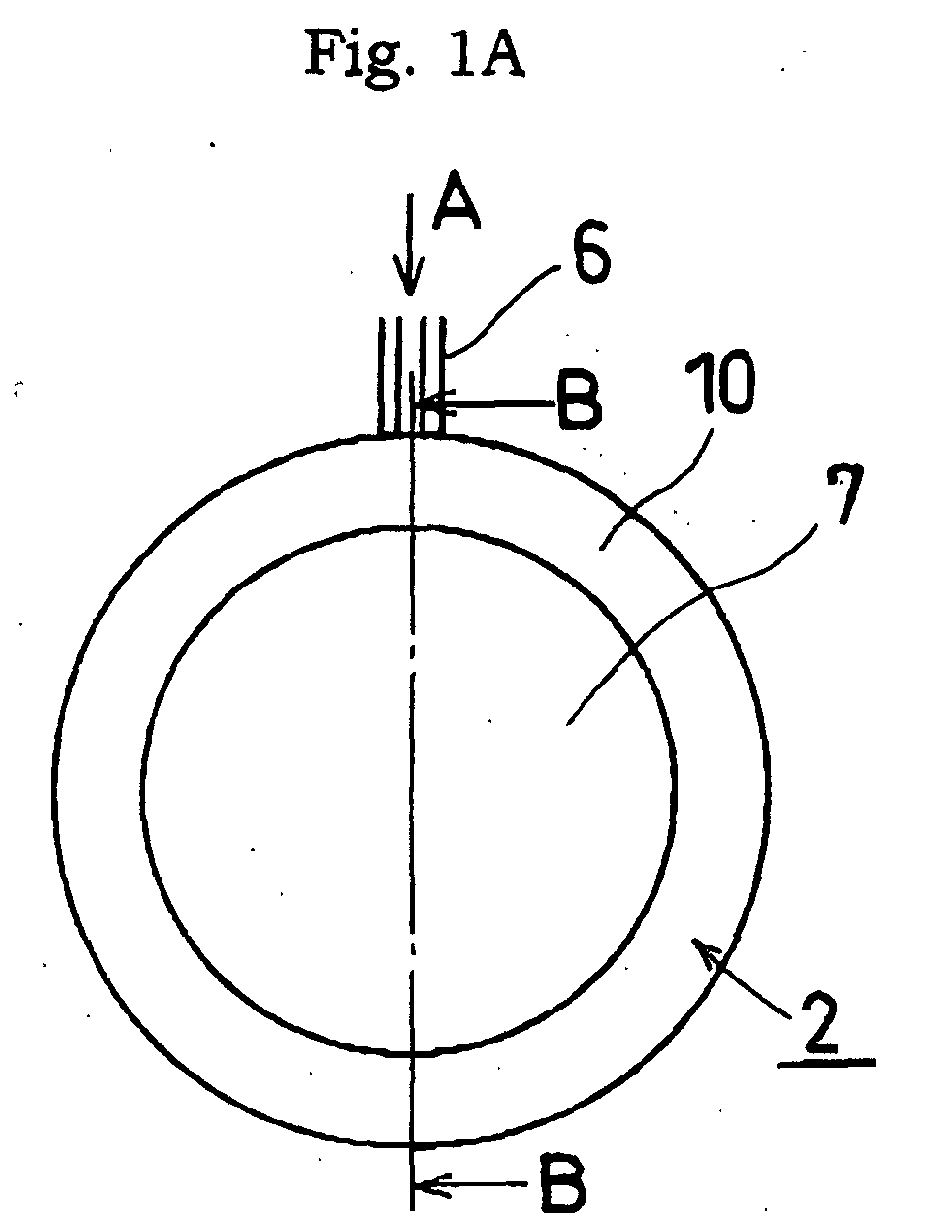
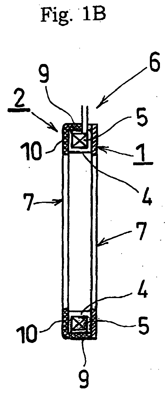
- Figs. 1A to 1C show a core structure of a stator transformer for a rotary transformer according to an embodiment of the present invention, wherein Fig. 1A is an front view thereof, Fig. 1B is a cross-sectional view taken along line B-B in Fig. 1A, and Fig. 1C is a top view seen from the direction of the arrow A in Fig. 1A.
- Figs. 2A to 2C are explanatory views of a concave metal ring, wherein Fig. 2A shows the concave metal ring before processing, Fig. 2B shows the concave metal ring after processing, and Fig. 2C is a top view of Fig. 2B seen from the direction of the arrow A.
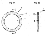
- Figs. 3A and 3B are explanatory views of a metal plate, wherein Fig. 3A is an front view thereof and Fig. 3B is a cross-sectional view taken along line C-C in Fig. 3A.
- Fig. 4 is a cross-sectional view of a conventional rotary transformer.
- Fig. 5 is a cross-sectional view of the conventional stator transformer for a rotary transformer.
- Figs. 1A to 1C show a core structure of a stator transformer for a rotary transformer according to an embodiment of the present invention, wherein Fig. 1A is an front view thereof, Fig. 1B is a cross-sectional view taken along line B-B in Fig. 1A, and Fig. 1C is a top view seen from the direction of the arrow A in Fig. 1A.
- An embodiment of the stator transformer for a rotary transformer of a resolver or the like according to the present invention will be specifically described hereinbelow with reference to the drawings. Since the structure of the resolver is identical to that of the conventional example, only a stator transformer different from the conventional one will be described.
- a stator transformer shown in Fig. 1 is formed of a concave metal ring 2 formed by drawing a sheet of metal plate produced by pressing and a planer metal plate 1 processed by pressing.
- the concave metal ring 2 includes a bottom 10 having a through hole 7 in which a rotor (not shown) is to be disposed, and a side part 9 formed in the upright condition at the bottom 10.
- the side part 9 has a guide hole 3 for guiding a lead wire 6 connected to a stator transformer coil 5 to the outside formed in a circular or elliptic shape.
- the metal plate 1 has the through hole 7 formed therein, in which the rotor (not shown) is to be disposed.
- the concave metal ring 2 has therein the stator transformer coil 5 wound around a bobbin 4.
- the stator transformer coil 5 wound around the bobbin 4 is secured in the inside of the concave metal ring 2 with an adhesive, a molding material or the like.
- the metal plate 1 and the end of the side part 9 formed in the upright condition at the bottom of the concave metal ring 2 are integrated with each other by, for example, welding or force-fitting such that the through hole 7 of the metal plate 1 and the through hole 7 of the concave metal ring 2 are concentric.
- Figs. 2A to 2C are explanatory views of the concave metal ring 2, wherein Fig. 2A shows the concave metal ring 2 before processing, Fig. 2B shows the concave metal ring 2 after processing, and Fig. 2C is a top view of Fig. 2B seen from the direction of the arrow A.
- the concave metal ring 2 is manufactured as follows. First, a planar metal plate made of a magnetic material is stamped out by a well-known method to form a circular plate P having the through hole 7, in which the rotor is to be disposed at the center thereof, and the circular or elliptic guide hole 3 for guiding the lead wire 6 to the outside as shown in Fig. 2A.
- the circular plate P is made of a magnetic material which has a drawing property according to the thickness of the concave metal ring, such as a nickel-iron alloy (Permalloy), an iron-cobalt alloy, and a silicon steel.
- a nickel-iron alloy Permal
- the outer dimension of the circular plate P in Fig. 2A is determined in consideration of the plate thickness so as to match the outer dimension of the concave metal ring 2.
- a diameter portion 8 indicated by alternate long and short dashed lines is drawn by a well-known method to form the concave metal ring 2 as shown in Fig. 2B.
- the diameter ⁇ R1 of the portion 8 indicated by the alternate long and short dashed lines is substantially identical to the outside diameter ⁇ R2 of the concave metal ring 2.
- the concave metal ring 2, subject to drawing as described above, includes the bottom 10 having the through hole 7 in which the rotor is to be disposed, and the side part 9 formed in the upright condition thereon, and the side part 9 has the guide hole 3 formed therein.
- Figs. 3A and 3B are explanatory views of the metal plate 1, wherein Fig. 3A is an front view thereof and Fig. 3B is a cross sectional view taken along line C-C in Fig. 3A.
- the metal plate 1 is made of the same magnetic material as the concave metal ring 2, the outer diameter of the metal plate 1 is equal to that of the concave metal ring 2 subject to drawing, and inner of which the through hole 7 having the rotor disposed therein is formed.
- the metal plate 1 is produced in a manner similar to the method of stamping out the circular plate P.
- the stator transformer coil 5 wound around the bobbin 4 is disposed inside the concave metal ring 2, and the metal plate 1 and the concave metal ring 2 are integrated by, for example, welding such that the through hole 7 of the metal plate 1 and the through hole 7 of the concave metal ring 2 are concentric thereby forming the stator transformer for the rotary transformer as described in Fig. 1.
- the guide hole 3 for guiding the lead wire 6 to the outside is circular or elliptic in the embodiment of the invention, it may be of other shapes, for example, a cut-out formed in the direction of the metal plate 1. In such a case, the guide hole 3 is formed when the concave metal ring 2 is integrated with the metal plate 1.
- the core structure of the rotary transformer according to the first aspect of the invention includes the concave metal ring formed by drawing a sheet of metal plate produced by pressing and the one planer metal plate formed by pressing, wherein the stator transformer coil is disposed inside the concave metal ring, and the concave metal ring and the metal plate are integrated with each other. Consequently, a core suitable for the rotary transformer of a small-sized resolver or the like can be provided at low cost.
- the guide hole is formed on the side of the concave metal ring. Accordingly, the lead wire can easily be guided to the outside.
- the guide hole is formed before the concave metal ring is subject to drawing. Consequently, the guide hole can be formed without the influence of drawing.
- the concave metal ring is made of a magnetic material having the property of being drawn according to the thickness of the concave metal ring. Consequently, the concave metal ring can be easily drawn depending on the size of the core of the rotary transformer.
Landscapes
- Engineering & Computer Science (AREA)
- Power Engineering (AREA)
- Transmission And Conversion Of Sensor Element Output (AREA)
- Coils Of Transformers For General Uses (AREA)
Abstract
Description
Claims (4)
- A core structure of a stator transformer for a rotary transformer having a stator transformer coil and a guide hole for guiding a lead wire connected to the stator transformer coil to the outside, comprising:a concave metal ring formed by drawing a sheet of metal plate produced by pressing; anda planer metal plate formed by pressing, wherein:the metal plate has a through hole in which a rotor is to be disposed;the concave metal ring has a bottom having the through hole in which the rotor is to be disposed, and a side part formed in an upstanding condition at the bottom;the stator transformer coil is disposed inside the concave metal ring; andthe end of the side of the concave metal ring and the metal plate are integrally formed.
- A core structure of the stator transformer for a rotary transformer according to Claim 1, wherein the guide hole is formed on the side of the concave metal ring.
- A core structure of the stator transformer for a rotary transformer according to Claim 1 or 2, wherein the guide hole is formed on the side of the concave metal ring which is formed by drawing the metal plate produced by pressing.
- A core structure of the stator transformer for a rotary transformer according to any one of Claims 1 to 3, wherein the concave metal ring is made of a magnetic material having a property of being able to be drawn according to a thickness of the concave metal ring.
Applications Claiming Priority (2)
| Application Number | Priority Date | Filing Date | Title |
|---|---|---|---|
| JP2001315778 | 2001-10-12 | ||
| JP2001315778A JP2003124044A (en) | 2001-10-12 | 2001-10-12 | Core structure of stator transformer in rotary transformer |
Publications (2)
| Publication Number | Publication Date |
|---|---|
| EP1302953A2 true EP1302953A2 (en) | 2003-04-16 |
| EP1302953A3 EP1302953A3 (en) | 2004-06-30 |
Family
ID=19133895
Family Applications (1)
| Application Number | Title | Priority Date | Filing Date |
|---|---|---|---|
| EP02022762A Withdrawn EP1302953A3 (en) | 2001-10-12 | 2002-10-11 | Core structure of stator transformer for rotary transformer |
Country Status (3)
| Country | Link |
|---|---|
| US (2) | US20030102949A1 (en) |
| EP (1) | EP1302953A3 (en) |
| JP (1) | JP2003124044A (en) |
Cited By (1)
| Publication number | Priority date | Publication date | Assignee | Title |
|---|---|---|---|---|
| DE102009020327A1 (en) | 2009-05-07 | 2010-11-11 | Ltn Servotechnik Gmbh | resolver |
Families Citing this family (6)
| Publication number | Priority date | Publication date | Assignee | Title |
|---|---|---|---|---|
| DK199901436A (en) * | 1999-10-07 | 2001-04-08 | Vestas Wind System As | Wind turbine |
| JP2003294487A (en) * | 2002-04-02 | 2003-10-15 | Minebea Co Ltd | Mechanism for positioning rotor transformer |
| JP3643960B2 (en) * | 2002-10-09 | 2005-04-27 | ミネベア株式会社 | Winding fixing structure of rotary transformer type resolver |
| JP4644055B2 (en) * | 2005-07-04 | 2011-03-02 | ミネベア株式会社 | High precision angle detector |
| WO2013185289A1 (en) * | 2012-06-12 | 2013-12-19 | 深圳市摩西尔电子有限公司 | Connector and signal transmission method |
| JP2017138222A (en) * | 2016-02-04 | 2017-08-10 | パナソニックIpマネジメント株式会社 | Rotation position detector |
Family Cites Families (11)
| Publication number | Priority date | Publication date | Assignee | Title |
|---|---|---|---|---|
| GB1239290A (en) * | 1968-10-17 | 1971-07-14 | ||
| US4117436A (en) * | 1976-08-23 | 1978-09-26 | The Charles Stark Draper Laboratory, Inc. | Torqueless relatively moving transformer windings |
| US4754180A (en) * | 1985-04-01 | 1988-06-28 | Honeywell Inc. | Forceless non-contacting power transformer |
| US4891567A (en) * | 1987-07-16 | 1990-01-02 | Minebea Co., Ltd. | Brushless DC motor having an outer rotor |
| US4910488A (en) * | 1989-07-17 | 1990-03-20 | Sarcos Group | Rotary variable differential transformer with eccentric rotor core |
| JP2539053B2 (en) * | 1989-09-25 | 1996-10-02 | 三菱電機株式会社 | Method of manufacturing rotating electric machine |
| US5881448A (en) * | 1992-04-06 | 1999-03-16 | General Electric Company | Method for making permanent magnet rotor |
| JPH05308768A (en) * | 1992-04-28 | 1993-11-19 | Minebea Co Ltd | Stator yoke for stepping motor |
| JP3060358B2 (en) * | 1994-06-24 | 2000-07-10 | 富士電気化学株式会社 | Method of manufacturing stator yoke and stator yoke |
| DE19527156C1 (en) * | 1995-07-25 | 1996-08-01 | Siemens Ag | Hollow shaft resolver with phase shift compensation |
| US5890277A (en) * | 1996-11-04 | 1999-04-06 | General Electric Company | Method for manufacturing a claw pole stator structure |
-
2001
- 2001-10-12 JP JP2001315778A patent/JP2003124044A/en active Pending
-
2002
- 2002-10-11 US US10/268,991 patent/US20030102949A1/en not_active Abandoned
- 2002-10-11 EP EP02022762A patent/EP1302953A3/en not_active Withdrawn
-
2005
- 2005-06-07 US US11/146,156 patent/US20050217107A1/en not_active Abandoned
Cited By (5)
| Publication number | Priority date | Publication date | Assignee | Title |
|---|---|---|---|---|
| DE102009020327A1 (en) | 2009-05-07 | 2010-11-11 | Ltn Servotechnik Gmbh | resolver |
| WO2010127728A1 (en) | 2009-05-07 | 2010-11-11 | Ltn Servotechnik Gmbh | Resolver |
| CN102395862A (en) * | 2009-05-07 | 2012-03-28 | Ltn伺服技术有限责任公司 | Resolver |
| US9013178B2 (en) | 2009-05-07 | 2015-04-21 | Ltn Servotechnik Gmbh | Resolver |
| CN102395862B (en) * | 2009-05-07 | 2015-05-20 | Ltn伺服技术有限责任公司 | Resolver |
Also Published As
| Publication number | Publication date |
|---|---|
| JP2003124044A (en) | 2003-04-25 |
| US20050217107A1 (en) | 2005-10-06 |
| US20030102949A1 (en) | 2003-06-05 |
| EP1302953A3 (en) | 2004-06-30 |
Similar Documents
| Publication | Publication Date | Title |
|---|---|---|
| US7626306B2 (en) | Laminated core structure of motor | |
| US7414348B2 (en) | Armature core of rotating electric machine | |
| JP2008211948A (en) | Manufacturing method of laminated rotor core | |
| US20050217107A1 (en) | Core structure of stator transformer for rotary transformer | |
| CN100568682C (en) | Stator of a reciprocating motor | |
| JP6250149B2 (en) | Armature core of rotating electrical machine and method for manufacturing armature | |
| JP3379461B2 (en) | Core member laminating mold apparatus, core member laminating method and electric motor | |
| US7592725B2 (en) | Motor and manufacturing method therefor | |
| US7197823B2 (en) | Method for manufacturing cylindrical members and method for manufacturing motors having the cylindrical member | |
| JP2005160138A (en) | Stator core | |
| US6759786B2 (en) | Stator of a brushless direct current motor and a method for making it | |
| JP2955804B2 (en) | Electric motor laminated iron core | |
| JP4657661B2 (en) | Manufacturing method of laminated stator core | |
| JP3795781B2 (en) | Core sheet, core sheet manufacturing method, stator and electric motor | |
| JP3186098U (en) | Core members and coil parts | |
| JP3671171B2 (en) | Coil device and manufacturing method thereof | |
| KR102040127B1 (en) | Method for setting up motor core plate concentricity | |
| JP7067564B2 (en) | Stator core manufacturing method | |
| JP2018042352A (en) | Manufacturing method for stator | |
| JP2016077154A (en) | Manufacturing method of core for rotary electric machine | |
| JP4002876B2 (en) | stator | |
| JPH0555062A (en) | Choke coil and fabrication thereof | |
| JPH11299134A (en) | Stator core | |
| JPH11176655A (en) | Coil having magnetic core | |
| JPH0470681B2 (en) |
Legal Events
| Date | Code | Title | Description |
|---|---|---|---|
| PUAI | Public reference made under article 153(3) epc to a published international application that has entered the european phase |
Free format text: ORIGINAL CODE: 0009012 |
|
| AK | Designated contracting states |
Designated state(s): AT BE BG CH CY CZ DE DK EE ES FI FR GB GR IE IT LI LU MC NL PT SE SK TR |
|
| AX | Request for extension of the european patent |
Extension state: AL LT LV MK RO SI |
|
| PUAL | Search report despatched |
Free format text: ORIGINAL CODE: 0009013 |
|
| AK | Designated contracting states |
Kind code of ref document: A3 Designated state(s): AT BE BG CH CY CZ DE DK EE ES FI FR GB GR IE IT LI LU MC NL PT SE SK TR |
|
| AX | Request for extension of the european patent |
Extension state: AL LT LV MK RO SI |
|
| RIC1 | Information provided on ipc code assigned before grant |
Ipc: 7H 01F 3/02 B Ipc: 7H 01F 38/18 A |
|
| 17P | Request for examination filed |
Effective date: 20040821 |
|
| AKX | Designation fees paid |
Designated state(s): DE FR GB IT |
|
| STAA | Information on the status of an ep patent application or granted ep patent |
Free format text: STATUS: THE APPLICATION IS DEEMED TO BE WITHDRAWN |
|
| 18D | Application deemed to be withdrawn |
Effective date: 20080503 |