US7414348B2 - Armature core of rotating electric machine - Google Patents
Armature core of rotating electric machine Download PDFInfo
- Publication number
- US7414348B2 US7414348B2 US11/855,218 US85521807A US7414348B2 US 7414348 B2 US7414348 B2 US 7414348B2 US 85521807 A US85521807 A US 85521807A US 7414348 B2 US7414348 B2 US 7414348B2
- Authority
- US
- United States
- Prior art keywords
- magnetic tooth
- sheet members
- portions
- electric machine
- rotating electric
- Prior art date
- Legal status (The legal status is an assumption and is not a legal conclusion. Google has not performed a legal analysis and makes no representation as to the accuracy of the status listed.)
- Expired - Lifetime
Links
- 238000010030 laminating Methods 0.000 claims abstract description 14
- 230000002093 peripheral effect Effects 0.000 claims description 6
- 238000000465 moulding Methods 0.000 claims description 5
- 239000011347 resin Substances 0.000 claims description 5
- 229920005989 resin Polymers 0.000 claims description 5
- 238000005520 cutting process Methods 0.000 claims description 3
- 239000011810 insulating material Substances 0.000 claims 2
- 238000004804 winding Methods 0.000 description 11
- 238000005304 joining Methods 0.000 description 10
- 238000000034 method Methods 0.000 description 6
- XEEYBQQBJWHFJM-UHFFFAOYSA-N Iron Chemical group [Fe] XEEYBQQBJWHFJM-UHFFFAOYSA-N 0.000 description 4
- 238000003466 welding Methods 0.000 description 4
- 238000003754 machining Methods 0.000 description 3
- 229910000831 Steel Inorganic materials 0.000 description 2
- 230000007423 decrease Effects 0.000 description 2
- 238000010586 diagram Methods 0.000 description 2
- 238000004519 manufacturing process Methods 0.000 description 2
- 239000010959 steel Substances 0.000 description 2
- 230000006835 compression Effects 0.000 description 1
- 238000007906 compression Methods 0.000 description 1
- 238000002788 crimping Methods 0.000 description 1
Images


Classifications
-
- H—ELECTRICITY
- H02—GENERATION; CONVERSION OR DISTRIBUTION OF ELECTRIC POWER
- H02K—DYNAMO-ELECTRIC MACHINES
- H02K1/00—Details of the magnetic circuit
- H02K1/06—Details of the magnetic circuit characterised by the shape, form or construction
- H02K1/12—Stationary parts of the magnetic circuit
- H02K1/14—Stator cores with salient poles
- H02K1/146—Stator cores with salient poles consisting of a generally annular yoke with salient poles
- H02K1/148—Sectional cores
-
- H—ELECTRICITY
- H02—GENERATION; CONVERSION OR DISTRIBUTION OF ELECTRIC POWER
- H02K—DYNAMO-ELECTRIC MACHINES
- H02K1/00—Details of the magnetic circuit
- H02K1/06—Details of the magnetic circuit characterised by the shape, form or construction
- H02K1/22—Rotating parts of the magnetic circuit
- H02K1/24—Rotor cores with salient poles ; Variable reluctance rotors
-
- H—ELECTRICITY
- H02—GENERATION; CONVERSION OR DISTRIBUTION OF ELECTRIC POWER
- H02K—DYNAMO-ELECTRIC MACHINES
- H02K15/00—Methods or apparatus specially adapted for manufacturing, assembling, maintaining or repairing of dynamo-electric machines
- H02K15/02—Methods or apparatus specially adapted for manufacturing, assembling, maintaining or repairing of dynamo-electric machines of stator or rotor bodies
- H02K15/022—Methods or apparatus specially adapted for manufacturing, assembling, maintaining or repairing of dynamo-electric machines of stator or rotor bodies with salient poles or claw-shaped poles
-
- H—ELECTRICITY
- H02—GENERATION; CONVERSION OR DISTRIBUTION OF ELECTRIC POWER
- H02K—DYNAMO-ELECTRIC MACHINES
- H02K1/00—Details of the magnetic circuit
- H02K1/06—Details of the magnetic circuit characterised by the shape, form or construction
- H02K1/22—Rotating parts of the magnetic circuit
- H02K1/28—Means for mounting or fastening rotating magnetic parts on to, or to, the rotor structures
-
- H—ELECTRICITY
- H02—GENERATION; CONVERSION OR DISTRIBUTION OF ELECTRIC POWER
- H02K—DYNAMO-ELECTRIC MACHINES
- H02K5/00—Casings; Enclosures; Supports
- H02K5/04—Casings or enclosures characterised by the shape, form or construction thereof
- H02K5/08—Insulating casings
Definitions
- the present invention relates to an armature core of a rotating electric machine, the armature core having a split structure of which components can be easily joined and fixed together to form a single body.
- a conventional rotating electric machine armature core is shown in Japanese Laid-open Patent Application No. 1999-155263, in which the armature core is structured by winding coils around tooth portions of a laminated iron core which is formed by laminating elemental iron core steel sheets having a plurality of tooth portions which are connected by joint parts and arranged in an annular shape, and then fixedly joining the elemental iron core steel sheets to a yoke portion located on an inner peripheral parts or an outer peripheral parts of the tooth portions to form a single body by compressing and deforming the laminated iron core to a predetermined outer diameter from outer peripheral directions thereof.
- the armature core is structured by winding armature coils around coil-winding pole portions of a plurality of divided cores, each of which includes a coil-winding pole portion and a divided yoke portion, and then fixedly joining the divided yoke portions of the individual divided cores to form a single body with the divided yoke portions fixed to a boss portion under conditions where joint surfaces of the divided yoke portions are magnetically connected to one another.
- the tooth portions are fixedly joined to the yoke portion by compressing and deforming the joint parts to form a single body after winding the coils around the tooth portions which are connected to the yoke portion via the joint parts. Therefore, in a case where the core is made compact, for example, there has been a problem that it is structurally difficult to form a space for accommodating the joint parts before and after the joint parts are deformed by compression, for instance, and the scope of application of this structure is limited.
- This invention has been made to solve the aforementioned problems. Accordingly, it is an object of the invention to provide a rotating electric machine armature core which makes it possible to achieve an improvement in the efficiency of assembly work for fixedly joining separate elements into a single body without limiting the scope of application of the armature core.
- a first rotating electric machine armature core includes such a number of magnetic tooth sections that corresponds to the number of magnetic poles, each of the magnetic tooth sections being formed by laminating a specific number of sheet members each of which has a magnetic tooth portion formed at one end and a back yoke portion formed at the other end, the magnetic tooth sections being combined in a radial form centering on the other end side and fixedly joined to together form a single body.
- Each of the magnetic tooth sections includes a plurality of first sheet members each of which includes the magnetic tooth portion formed at one end and a root portion formed at the other end with an end face of the root portion having a prescribed external shape, and at least one second sheet member inserted between the individual first sheet members in a laminating direction thereof at a location different from the locations of the other sheet members, the second sheet member including the magnetic tooth portion formed at one end and an overlapping portion formed at the other end, the overlapping portion forming the back yoke portion together with the root portion with a through hole formed at a specified position in the overlapping portion, the overlapping portion jutting out from the root portion in such a manner that the overlapping portion can fit on the end face of the root portion of the first sheet member.
- This rotating electric machine armature core is configured by combining the magnetic tooth sections with the through holes in the individual overlapping portions aligned at the same location.
- This structure makes it possible to provide a rotating electric machine armature core which allows for an improvement in the efficiency of assembly work for fixedly joining separate elements into a single body without limiting the scope of application of the armature core.
- a second rotating electric machine armature core includes a first magnetic tooth section including first sheet members each of which includes a ringlike portion having a through hole at a central part and a plurality of magnetic tooth portions formed to extend from around the aforesaid ringlike portion at specific intervals along a circumferential direction, and second sheet members each of which includes a second ringlike portion, a plurality of magnetic tooth portions formed to extend from around the aforesaid second ringlike portion at the specific intervals along the circumferential direction, and a cutout portion opening outward at a middle position along the circumferential direction between adjacent two of the aforesaid magnetic tooth portions, the aforesaid cutout portion being formed by cutting out a central part of the aforesaid second ringlike portion over an area large enough to encompass the through hole formed in the aforesaid first sheet members, wherein the aforesaid first magnetic tooth section is formed by laminating specific numbers of the aforesaid first magnetic tooth section is
- This rotating electric machine armature core is characterized in that the same is configured by combining the aforesaid first and second magnetic tooth sections with the overlapping portions of the aforesaid second magnetic tooth sections fitted in the corresponding cutout portions of the aforesaid first magnetic tooth section.
- This structure makes it possible to achieve an improvement in the efficiency of assembly work for fixedly joining separate elements into a single body without requiring difficult machining even when the core size is reduced.
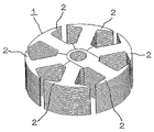
- FIG. 1 is a perspective view showing the structure of a rotating electric machine armature core according to a first embodiment of this invention
- FIG. 2 is an exploded perspective view showing the rotating electric machine armature core of FIG. 1 ;
- FIG. 3 is a perspective view showing a state in which one of magnetic tooth sections of the rotating electric machine armature core of FIG. 1 has been detached;
- FIG. 4 is a plan view showing the rotating electric machine armature core of FIG. 1 ;
- FIG. 5 is a cross-sectional view showing a cross section taken along a line V-V of FIG. 4 ;
- FIG. 6 is a diagram showing a process of winding coils on the rotating electric machine armature core of FIG. 1 ;
- FIG. 7 is a perspective view showing an example in which the magnetic tooth sections of the rotating electric machine armature core of FIG. 1 have been fixedly combined into a single body by forcibly inserting a rotary shaft;
- FIG. 8 is a cross-sectional view showing an example in which the rotating electric machine armature core sections of FIG. 1 have been fixedly combined into a single body by welding;
- FIG. 9 is an exploded perspective view showing the structure of a rotating electric machine armature core according to a second embodiment of this invention.
- FIG. 10 is a fragmentary cross-sectional view showing the structure of a principal part of the rotating electric machine armature core of FIG. 9 ;
- FIG. 11 is a perspective view showing a process of manufacturing a first magnetic tooth section shown in FIG. 9 ;
- FIG. 12 is a perspective view showing a process of manufacturing a second magnetic tooth section shown in FIG. 9 ;
- FIG. 13 is a fragmentary cross-sectional view showing the structure of a principal part of a rotating electric machine armature core according to a third embodiment of this invention.
- FIG. 1 is a perspective view showing the structure of an armature core of a rotating electric machine according to a first embodiment of this invention
- FIG. 2 is an exploded perspective view showing the rotating electric machine armature core of FIG. 1
- FIG. 3 is a perspective view showing a state in which one of magnetic tooth sections of the rotating electric machine armature core of FIG. 1 has been detached
- FIG. 4 is a plan view showing the rotating electric machine armature core of FIG. 1
- FIG. 5 is a cross-sectional view showing a cross section taken along a line V-V of FIG. 4
- FIG. 6 is a diagram showing a process of winding coils on the rotating electric machine armature core of FIG. 1
- FIG. 7 is a perspective view showing an example in which the magnetic tooth sections of the rotating electric machine armature core of FIG. 1 have been fixedly combined into a single body by forcibly inserting a rotary shaft
- FIG. 8 is a cross-sectional view showing an example in which the rotating electric machine armature core sections of FIG. 1 have been fixedly combined into a single body by welding.
- the rotating electric machine armature core 1 of the first embodiment is configured by combining such a number of magnetic tooth sections 2 that corresponds to the number of magnetic poles in a radial form as shown in FIG. 1 .
- Each of the magnetic tooth sections 2 includes first sheet members 6 and at least one second sheet member 10 inserted between the first sheet members 6 in a laminating direction thereof at a location different from the locations of the other magnetic tooth sections 2 .
- Each of the first sheet members 6 includes a magnetic tooth portion 3 formed at one end and a root portion 5 formed at the other end with an end face 4 of the root portion 5 having a prescribed external shape (arch shape as illustrated).
- the second sheet member 10 includes a magnetic tooth portion 3 formed at one end and an overlapping portion 9 formed at the other end, wherein the overlapping portion 9 forms a back yoke portion 8 together with a root portion 5 with a through hole 7 formed at a specified position in the overlapping portion 9 , the overlapping portion 9 jutting out from the root portion 5 in such a fashion that the overlapping portion 9 can fit on the end faces 4 of the root portions 5 of the pertinent first sheet members 6 .
- the individual magnetic tooth sections 2 structured as described above are fixedly combined into a single body by crimping the magnetic tooth sections 2 at specified locations marked by asterisks (*) in FIGS. 4 and 5 .
- the magnetic tooth sections 2 are combined in a radial form, centering on the individual overlapping portions 9 , in such a way that the through holes 7 of the individual overlapping portions 9 are aligned with one another, and end faces of the individual overlapping portions 9 fit on the end faces 4 of the root portions 5 of the other magnetic tooth sections 2 as shown in FIGS. 2 and 3 .
- the individual magnetic tooth sections 2 are joined into a single body by forcibly fitting the rotary shaft 11 into the through holes 7 , whereby the rotating electric machine armature core 1 is completed.
- each of the individual magnetic tooth sections 2 is pulled out in a radial direction from a state shown in FIG. 6(A) and subjected to coil-winding operation performed by a coil winding machine 12 as shown in FIG. 6(B) to wind a coil 13 around the magnetic tooth portion 3 as shown in FIG. 6(C) . Subsequently, the coils 13 are successively wound on the remaining magnetic tooth sections 2 as shown in FIG. 6(D) .
- the individual magnetic tooth sections 2 are structured as discussed above, such a number of magnetic tooth sections 2 that corresponds to the number of magnetic poles are combined in a radial form in such a way that locations of the individual through holes 7 of the overlapping portions 9 align one another, centering on a side where the overlapping portions 9 are formed, and the individual magnetic tooth sections 2 are fixedly combined into a single body by forcibly fitting the rotary shaft 11 into the through holes 7 in the individual overlapping portions 9 . Therefore, it is possible to achieve an improvement in the efficiency of assembly work for fixedly joining separate elements into a single body without requiring difficult machining even when the core size is reduced.
- the aforementioned structure allows for an improvement in the assembly work efficiency by forcibly fitting the rotary shaft 11 into the individual through holes 7 in the overlapping portions 9 to fixedly combine the individual magnetic tooth sections 2
- the invention is not limited to this structure.
- a rotating electric machine armature core 21 according to a second embodiment of this invention is configured by combining a first magnetic tooth section 22 disposed at a central position and a plurality of second magnetic tooth sections 31 disposed in surrounding areas of the first magnetic tooth section 22 as shown in FIG. 9 .
- FIG. 10 is a fragmentary cross-sectional view showing the structure of a principal part of the rotating electric machine armature core of FIG. 9 .
- the first magnetic tooth section 22 is configured by laminating specific numbers of first sheet members 26 and second sheet members 30 as shown in FIG. 11 .
- Each of the first sheet members 26 includes a ringlike portion 24 having a through hole 23 at a central part and a plurality of magnetic tooth portions 25 formed to extend from around this ringlike portion 24 at specific intervals along a circumferential direction.
- Each of the second sheet members 30 has the second sheet member 30 which includes a second ringlike portion 27 , a plurality of magnetic tooth portions 28 formed to extend from around this second ringlike portion 27 at the same intervals as the magnetic tooth portions 25 of the first sheet member 26 along the circumferential direction, and a cutout portion 29 opening outward at a middle position along the circumferential direction between adjacent two of the magnetic tooth portions 28 , the cutout portion 29 being formed by cutting out a central part of the second ringlike portion 27 over an area larger than the through hole 23 formed in the first sheet member 26 .
- the first sheet members 26 and the second sheet members 30 are laminated in such a manner that the individual magnetic tooth portions 25 , 28 are aligned and the cutout portion 29 of the second sheet member 30 exists at least at one location between the adjacent magnetic tooth portions 25 , 28 .
- the second magnetic tooth section 31 is configured by laminating specific numbers of third sheet members 34 and fourth sheet members 38 as shown in FIG. 12 .
- Each of the third sheet members 34 includes a magnetic tooth portion 32 formed at one end and an end portion 33 formed at the other end, the end portion 33 being capable of fitting on an outer peripheral surface of the ringlike portion 24 of the relevant first sheet member 26 .
- Each of the fourth sheet members 38 includes a magnetic tooth portion 35 formed at one end and an overlapping portion 37 formed at the other end with a through hole 36 formed at a specified position in the overlapping portion 37 , the overlapping portion 37 being capable of fitting in the cutout portion 29 of the relevant second sheet member 30 .
- the third sheet members 34 and the fourth sheet members 38 are laminated in such a manner that the individual magnetic tooth portions 32 , 35 are aligned and each of the fourth sheet members 38 is placed between the second sheet members 30 with the fourth sheet members 38 aligned at the same locations as the cutout portions 29 of the second sheet members 30 in their laminating direction and with the overlapping portions 37 of the fourth sheet members 38 jutting out farther beyond the end portions 33 of the third sheet members 34 .
- the first magnetic tooth section 22 and the second magnetic tooth sections 31 are combined by fitting the overlapping portions 37 of the second magnetic tooth sections 31 in the corresponding cutout portions 29 of the first magnetic tooth section 22 such that the through holes 23 , 36 on both sides are aligned together. Then, although not illustrated, the first magnetic tooth section 22 and the individual second magnetic tooth sections 31 are joined into a single body by forcibly fitting a rotary shaft into the through holes 23 , 36 or by welding the first magnetic tooth section 22 and the individual second magnetic tooth sections 31 from an inner periphery side of the individual through holes 23 , 36 , whereby the rotating electric machine armature core 21 is completed.
- coils are wound around the individual magnetic tooth portions 25 , 28 and 32 , 35 of both types of magnetic tooth sections 22 , 31 in the same way as in the first embodiment.
- the first and second magnetic tooth sections 22 , 31 are structured as discussed above and are fixedly joined into a single body with the overlapping portions 37 of the second magnetic tooth sections 31 fitted in the cutout portions 29 of the corresponding second sheet members 30 such that the through holes 36 in the overlapping portions 37 are aligned with the through holes 23 in the first sheet members 26 . Therefore, it is possible to achieve an improvement in the efficiency of assembly work for fixedly joining separate elements into a single body without requiring difficult machining even when the core size is reduced.
- FIG. 13 is a fragmentary cross-sectional view showing the structure of a principal part of a rotating electric machine armature core according to a third embodiment of this invention, in which elements similar to those of the aforementioned first embodiment are designated by the same reference numerals and a description of such elements is omitted.
- the rotating electric machine armature core of the third embodiment of this invention is configured in such a manner that surfaces of individual magnetic tooth sections 2 are covered with molding resin 42 and extreme end parts 43 of a magnetic tooth portion 3 of each magnetic tooth section 2 extend so that a slot opening between extreme ends of one magnetic tooth portion 3 and another is closed.
- the aforementioned structure makes it possible to decrease windage loss by reducing passage flow resistance of air gaps and thereby increase the efficiency of a rotating electric machine.
- the present invention provides a rotating electric machine armature core which makes it possible to achieve an improvement in the efficiency of assembly work for fixedly joining separate elements into a single body, the rotating electric machine armature core offering a wide range of applications.
Abstract
A rotating electric machine armature core is configured by combining such a number of magnetic tooth sections that corresponds to the number of magnetic poles, each of the magnetic tooth sections including a plurality of first sheet members each of which includes a magnetic tooth portion formed at one end and a root portion formed at the other end with an end face of the root portion having a prescribed external shape, and at least one second sheet member inserted between the individual first sheet members in a laminating direction thereof at a location different from the locations of the other sheet members, the second sheet member including the magnetic tooth portion formed at one end and an overlapping portion formed at the other end, the overlapping portion forming a back yoke portion together with the root portion with a through hole formed at a specified position in the overlapping portion, the overlapping portion jutting out from the root portion in such a manner that the overlapping portion can fit on the end face of the root portion of the first sheet member, wherein the magnetic tooth sections are combined in a radial form with the through holes in the individual overlapping portions aligned at the same location.
Description
This is a divisional of U.S. application Ser. No. 10/549,185, filed Sep. 16, 2005, now U.S. Published Application No. US-2007-0035199-A1, the entire contents of which is hereby incorporated by reference.
The present invention relates to an armature core of a rotating electric machine, the armature core having a split structure of which components can be easily joined and fixed together to form a single body.
An example of a conventional rotating electric machine armature core is shown in Japanese Laid-open Patent Application No. 1999-155263, in which the armature core is structured by winding coils around tooth portions of a laminated iron core which is formed by laminating elemental iron core steel sheets having a plurality of tooth portions which are connected by joint parts and arranged in an annular shape, and then fixedly joining the elemental iron core steel sheets to a yoke portion located on an inner peripheral parts or an outer peripheral parts of the tooth portions to form a single body by compressing and deforming the laminated iron core to a predetermined outer diameter from outer peripheral directions thereof.
Another example is shown in Japanese Laid-open Patent Application No. 1999-146581, in which the armature core is structured by winding armature coils around coil-winding pole portions of a plurality of divided cores, each of which includes a coil-winding pole portion and a divided yoke portion, and then fixedly joining the divided yoke portions of the individual divided cores to form a single body with the divided yoke portions fixed to a boss portion under conditions where joint surfaces of the divided yoke portions are magnetically connected to one another.
In the conventional rotating electric machine armature core described above with reference to Japanese Laid-open Patent Application No. 1999-155263, the tooth portions are fixedly joined to the yoke portion by compressing and deforming the joint parts to form a single body after winding the coils around the tooth portions which are connected to the yoke portion via the joint parts. Therefore, in a case where the core is made compact, for example, there has been a problem that it is structurally difficult to form a space for accommodating the joint parts before and after the joint parts are deformed by compression, for instance, and the scope of application of this structure is limited.
In the Japanese Laid-open Patent Application No. 1999-146581, on the other hand, the individual divided cores are fixedly joined by fixing the same to a boss to form a single body after winding the coils around the coil-winding pole portions of the individual divided cores. Thus, although the scope of application of this structure is not limited, there has been a problem that work for fixing the individual divided cores to the boss one by one is so complex that efficiency of assembly work for fixedly joining the divided cores into a single body decreases in this approach.
This invention has been made to solve the aforementioned problems. Accordingly, it is an object of the invention to provide a rotating electric machine armature core which makes it possible to achieve an improvement in the efficiency of assembly work for fixedly joining separate elements into a single body without limiting the scope of application of the armature core.
A first rotating electric machine armature core according to the present invention includes such a number of magnetic tooth sections that corresponds to the number of magnetic poles, each of the magnetic tooth sections being formed by laminating a specific number of sheet members each of which has a magnetic tooth portion formed at one end and a back yoke portion formed at the other end, the magnetic tooth sections being combined in a radial form centering on the other end side and fixedly joined to together form a single body. Each of the magnetic tooth sections includes a plurality of first sheet members each of which includes the magnetic tooth portion formed at one end and a root portion formed at the other end with an end face of the root portion having a prescribed external shape, and at least one second sheet member inserted between the individual first sheet members in a laminating direction thereof at a location different from the locations of the other sheet members, the second sheet member including the magnetic tooth portion formed at one end and an overlapping portion formed at the other end, the overlapping portion forming the back yoke portion together with the root portion with a through hole formed at a specified position in the overlapping portion, the overlapping portion jutting out from the root portion in such a manner that the overlapping portion can fit on the end face of the root portion of the first sheet member. This rotating electric machine armature core is configured by combining the magnetic tooth sections with the through holes in the individual overlapping portions aligned at the same location.
This structure makes it possible to provide a rotating electric machine armature core which allows for an improvement in the efficiency of assembly work for fixedly joining separate elements into a single body without limiting the scope of application of the armature core.
A second rotating electric machine armature core according to the present invention includes a first magnetic tooth section including first sheet members each of which includes a ringlike portion having a through hole at a central part and a plurality of magnetic tooth portions formed to extend from around the aforesaid ringlike portion at specific intervals along a circumferential direction, and second sheet members each of which includes a second ringlike portion, a plurality of magnetic tooth portions formed to extend from around the aforesaid second ringlike portion at the specific intervals along the circumferential direction, and a cutout portion opening outward at a middle position along the circumferential direction between adjacent two of the aforesaid magnetic tooth portions, the aforesaid cutout portion being formed by cutting out a central part of the aforesaid second ringlike portion over an area large enough to encompass the through hole formed in the aforesaid first sheet members, wherein the aforesaid first magnetic tooth section is formed by laminating specific numbers of the aforesaid first and second sheet members in such a manner that the individual magnetic tooth portions of the aforesaid first and second laminated members are aligned and the cutout portion of the aforesaid second sheet member exists at least at one location between the aforesaid adjacent magnetic tooth portions, and a plurality of second magnetic tooth sections each including third sheet members each of which includes a magnetic tooth portion formed at one end and an end portion formed at the other end, the end portion being capable of fitting on an outer peripheral surface of the ringlike portion of the aforesaid first sheet member, and fourth sheet members each of which includes a magnetic tooth portion formed at one end and an overlapping portion formed at the other end with a through hole formed at a specified position in the overlapping portion, the overlapping portion being capable of fitting in the cutout portion of the aforesaid second sheet member, wherein each of the aforesaid second magnetic tooth sections is formed by laminating the specific numbers of the aforesaid third and fourth sheet members in such a manner that the individual magnetic tooth portions of the aforesaid third and fourth sheet members are aligned and each of the aforesaid fourth sheet members is placed between the aforesaid second sheet members with the aforesaid fourth sheet members aligned at the same locations as the cutout portions of the aforesaid second sheet members in a laminating direction and with the overlapping portions of the aforesaid fourth sheet members jutting out farther beyond the end portions of the aforesaid third sheet members. This rotating electric machine armature core is characterized in that the same is configured by combining the aforesaid first and second magnetic tooth sections with the overlapping portions of the aforesaid second magnetic tooth sections fitted in the corresponding cutout portions of the aforesaid first magnetic tooth section.
This structure makes it possible to achieve an improvement in the efficiency of assembly work for fixedly joining separate elements into a single body without requiring difficult machining even when the core size is reduced.
Now, best modes for carrying out the present invention are described in the following with reference to the drawings.
The rotating electric machine armature core 1 of the first embodiment is configured by combining such a number of magnetic tooth sections 2 that corresponds to the number of magnetic poles in a radial form as shown in FIG. 1 .
Each of the magnetic tooth sections 2 includes first sheet members 6 and at least one second sheet member 10 inserted between the first sheet members 6 in a laminating direction thereof at a location different from the locations of the other magnetic tooth sections 2. Each of the first sheet members 6 includes a magnetic tooth portion 3 formed at one end and a root portion 5 formed at the other end with an end face 4 of the root portion 5 having a prescribed external shape (arch shape as illustrated). The second sheet member 10 includes a magnetic tooth portion 3 formed at one end and an overlapping portion 9 formed at the other end, wherein the overlapping portion 9 forms a back yoke portion 8 together with a root portion 5 with a through hole 7 formed at a specified position in the overlapping portion 9, the overlapping portion 9 jutting out from the root portion 5 in such a fashion that the overlapping portion 9 can fit on the end faces 4 of the root portions 5 of the pertinent first sheet members 6.
The individual magnetic tooth sections 2 structured as described above are fixedly combined into a single body by crimping the magnetic tooth sections 2 at specified locations marked by asterisks (*) in FIGS. 4 and 5 .
Next, the magnetic tooth sections 2 are combined in a radial form, centering on the individual overlapping portions 9, in such a way that the through holes 7 of the individual overlapping portions 9 are aligned with one another, and end faces of the individual overlapping portions 9 fit on the end faces 4 of the root portions 5 of the other magnetic tooth sections 2 as shown in FIGS. 2 and 3 . Then, as shown in FIG. 7 , the individual magnetic tooth sections 2 are joined into a single body by forcibly fitting the rotary shaft 11 into the through holes 7, whereby the rotating electric machine armature core 1 is completed.
In a stage preceding the process of combining the individual magnetic tooth sections 2 into a single body by forcibly fitting the rotary shaft 11, each of the individual magnetic tooth sections 2 is pulled out in a radial direction from a state shown in FIG. 6(A) and subjected to coil-winding operation performed by a coil winding machine 12 as shown in FIG. 6(B) to wind a coil 13 around the magnetic tooth portion 3 as shown in FIG. 6(C) . Subsequently, the coils 13 are successively wound on the remaining magnetic tooth sections 2 as shown in FIG. 6(D) .
In the foregoing first embodiment, the individual magnetic tooth sections 2 are structured as discussed above, such a number of magnetic tooth sections 2 that corresponds to the number of magnetic poles are combined in a radial form in such a way that locations of the individual through holes 7 of the overlapping portions 9 align one another, centering on a side where the overlapping portions 9 are formed, and the individual magnetic tooth sections 2 are fixedly combined into a single body by forcibly fitting the rotary shaft 11 into the through holes 7 in the individual overlapping portions 9. Therefore, it is possible to achieve an improvement in the efficiency of assembly work for fixedly joining separate elements into a single body without requiring difficult machining even when the core size is reduced.
While the aforementioned structure allows for an improvement in the assembly work efficiency by forcibly fitting the rotary shaft 11 into the individual through holes 7 in the overlapping portions 9 to fixedly combine the individual magnetic tooth sections 2, the invention is not limited to this structure. As an alternative, it is possible to achieve an improvement in the assembly work efficiency by fixedly joining the individual magnetic tooth sections 2 by welding the same from an inner periphery side of the individual through holes 7 as shown by an arrow in FIG. 8 .
A rotating electric machine armature core 21 according to a second embodiment of this invention is configured by combining a first magnetic tooth section 22 disposed at a central position and a plurality of second magnetic tooth sections 31 disposed in surrounding areas of the first magnetic tooth section 22 as shown in FIG. 9 . FIG. 10 is a fragmentary cross-sectional view showing the structure of a principal part of the rotating electric machine armature core of FIG. 9 .
The first magnetic tooth section 22 is configured by laminating specific numbers of first sheet members 26 and second sheet members 30 as shown in FIG. 11 . Each of the first sheet members 26 includes a ringlike portion 24 having a through hole 23 at a central part and a plurality of magnetic tooth portions 25 formed to extend from around this ringlike portion 24 at specific intervals along a circumferential direction. Each of the second sheet members 30 has the second sheet member 30 which includes a second ringlike portion 27, a plurality of magnetic tooth portions 28 formed to extend from around this second ringlike portion 27 at the same intervals as the magnetic tooth portions 25 of the first sheet member 26 along the circumferential direction, and a cutout portion 29 opening outward at a middle position along the circumferential direction between adjacent two of the magnetic tooth portions 28, the cutout portion 29 being formed by cutting out a central part of the second ringlike portion 27 over an area larger than the through hole 23 formed in the first sheet member 26. The first sheet members 26 and the second sheet members 30 are laminated in such a manner that the individual magnetic tooth portions 25, 28 are aligned and the cutout portion 29 of the second sheet member 30 exists at least at one location between the adjacent magnetic tooth portions 25, 28.
The second magnetic tooth section 31 is configured by laminating specific numbers of third sheet members 34 and fourth sheet members 38 as shown in FIG. 12 . Each of the third sheet members 34 includes a magnetic tooth portion 32 formed at one end and an end portion 33 formed at the other end, the end portion 33 being capable of fitting on an outer peripheral surface of the ringlike portion 24 of the relevant first sheet member 26. Each of the fourth sheet members 38 includes a magnetic tooth portion 35 formed at one end and an overlapping portion 37 formed at the other end with a through hole 36 formed at a specified position in the overlapping portion 37, the overlapping portion 37 being capable of fitting in the cutout portion 29 of the relevant second sheet member 30. The third sheet members 34 and the fourth sheet members 38 are laminated in such a manner that the individual magnetic tooth portions 32, 35 are aligned and each of the fourth sheet members 38 is placed between the second sheet members 30 with the fourth sheet members 38 aligned at the same locations as the cutout portions 29 of the second sheet members 30 in their laminating direction and with the overlapping portions 37 of the fourth sheet members 38 jutting out farther beyond the end portions 33 of the third sheet members 34.
The first magnetic tooth section 22 and the second magnetic tooth sections 31 thus configured are combined by fitting the overlapping portions 37 of the second magnetic tooth sections 31 in the corresponding cutout portions 29 of the first magnetic tooth section 22 such that the through holes 23, 36 on both sides are aligned together. Then, although not illustrated, the first magnetic tooth section 22 and the individual second magnetic tooth sections 31 are joined into a single body by forcibly fitting a rotary shaft into the through holes 23, 36 or by welding the first magnetic tooth section 22 and the individual second magnetic tooth sections 31 from an inner periphery side of the individual through holes 23, 36, whereby the rotating electric machine armature core 21 is completed.
In a stage preceding the process of combining the second magnetic tooth sections 31 with the first magnetic tooth section 22 to form a single body, coils are wound around the individual magnetic tooth portions 25, 28 and 32, 35 of both types of magnetic tooth sections 22, 31 in the same way as in the first embodiment.
In the foregoing second embodiment, the first and second magnetic tooth sections 22, 31 are structured as discussed above and are fixedly joined into a single body with the overlapping portions 37 of the second magnetic tooth sections 31 fitted in the cutout portions 29 of the corresponding second sheet members 30 such that the through holes 36 in the overlapping portions 37 are aligned with the through holes 23 in the first sheet members 26. Therefore, it is possible to achieve an improvement in the efficiency of assembly work for fixedly joining separate elements into a single body without requiring difficult machining even when the core size is reduced.
The rotating electric machine armature core of the third embodiment of this invention is configured in such a manner that surfaces of individual magnetic tooth sections 2 are covered with molding resin 42 and extreme end parts 43 of a magnetic tooth portion 3 of each magnetic tooth section 2 extend so that a slot opening between extreme ends of one magnetic tooth portion 3 and another is closed. The aforementioned structure makes it possible to decrease windage loss by reducing passage flow resistance of air gaps and thereby increase the efficiency of a rotating electric machine.
As thus far discussed, the present invention provides a rotating electric machine armature core which makes it possible to achieve an improvement in the efficiency of assembly work for fixedly joining separate elements into a single body, the rotating electric machine armature core offering a wide range of applications.
Claims (4)
1. A rotating electric machine armature core comprising:
a first magnetic tooth section including:
first sheet members each of which includes a ringlike portion having a through hole at a central part and a plurality of magnetic tooth portions formed to extend from around said ringlike portion at specific intervals along a circumferential direction; and
second sheet members each of which includes a second ringlike portion, a plurality of magnetic tooth portions formed to extend from around said second ringlike portion at the specific intervals along the circumferential direction, and a cutout portion opening outward at a middle position along the circumferential direction between adjacent two of said magnetic tooth portions, said cutout portion being formed by cutting out a central part of said second ringlike portion over an area large enough to encompass the through hole formed in said first sheet members;
wherein said first magnetic tooth section is formed by laminating specific numbers of said first and second sheet members in such a manner that the individual magnetic tooth portions of said first and second laminated members are aligned and the cutout portion of said second sheet member exists at least at one location between said adjacent magnetic tooth portions; and
a plurality of second magnetic tooth sections each including:
third sheet members each of which includes a magnetic tooth portion formed at one end and an end portion formed at the other end, the end portion being capable of fitting on an outer peripheral surface of the ringlike portion of said first sheet member; and
fourth sheet members each of which includes a magnetic tooth portion formed at one end and an overlapping portion formed at the other end with a through hole formed at a specified position in the overlapping portion, the overlapping portion being capable of fitting in the cutout portion of said second sheet member;
wherein each of said second magnetic tooth sections is formed by laminating the specific numbers of said third and fourth sheet members in such a manner that the individual magnetic tooth portions of said third and fourth sheet members are aligned and each of said fourth sheet members is placed between said second sheet members with said fourth sheet members aligned at the same locations as the cutout portions of said second sheet members in a laminating direction and with the overlapping portions of said fourth sheet members jutting out farther beyond the end portions of said third sheet members; and
wherein said rotating electric machine armature core is configured by combining said first and second magnetic tooth sections with the overlapping portions of said second magnetic tooth sections fitted in the corresponding cutout portions of said first magnetic tooth section.
2. The rotating electric machine armature core according to claim 1 , wherein said magnetic tooth sections are fixedly joined to together form a single body by forcibly fitting a rotary shaft into said individual through holes.
3. The rotating electric machine armature core according to claim 1 , wherein the same is configured by using molding resin as an insulating material to cover said magnetic tooth portions in such a manner that parts of said molding resin extend to close a slot opening between extreme ends of one magnetic tooth portion and another.
4. The rotating electric machine armature core according to claim 1 , wherein
said magnetic tooth sections are fixedly joined to together form a single body by forcibly fitting a rotary shaft into said individual through holes, and
the same is configured by using molding resin as an insulating material to cover said magnetic tooth portions in such a manner that parts of said molding resin extend to close a slot opening between extreme ends of one magnetic tooth portion and another.
Priority Applications (1)
| Application Number | Priority Date | Filing Date | Title |
|---|---|---|---|
| US11/855,218 US7414348B2 (en) | 2004-03-03 | 2007-09-14 | Armature core of rotating electric machine |
Applications Claiming Priority (3)
| Application Number | Priority Date | Filing Date | Title |
|---|---|---|---|
| PCT/JP2004/002658 WO2005086318A1 (en) | 2004-03-03 | 2004-03-03 | Armature core for dynamo-electric machine |
| US54918505A | 2005-09-16 | 2005-09-16 | |
| US11/855,218 US7414348B2 (en) | 2004-03-03 | 2007-09-14 | Armature core of rotating electric machine |
Related Parent Applications (3)
| Application Number | Title | Priority Date | Filing Date |
|---|---|---|---|
| US10/549,185 Division US7285891B2 (en) | 2004-03-03 | 2004-03-03 | Armature core of rotating electric machine |
| PCT/JP2004/002658 Division WO2005086318A1 (en) | 2002-12-24 | 2004-03-03 | Armature core for dynamo-electric machine |
| US54918505A Division | 2004-03-03 | 2005-09-16 |
Publications (2)
| Publication Number | Publication Date |
|---|---|
| US20080018197A1 US20080018197A1 (en) | 2008-01-24 |
| US7414348B2 true US7414348B2 (en) | 2008-08-19 |
Family
ID=34917817
Family Applications (2)
| Application Number | Title | Priority Date | Filing Date |
|---|---|---|---|
| US10/549,185 Active 2024-08-30 US7285891B2 (en) | 2004-03-03 | 2004-03-03 | Armature core of rotating electric machine |
| US11/855,218 Expired - Lifetime US7414348B2 (en) | 2004-03-03 | 2007-09-14 | Armature core of rotating electric machine |
Family Applications Before (1)
| Application Number | Title | Priority Date | Filing Date |
|---|---|---|---|
| US10/549,185 Active 2024-08-30 US7285891B2 (en) | 2004-03-03 | 2004-03-03 | Armature core of rotating electric machine |
Country Status (4)
| Country | Link |
|---|---|
| US (2) | US7285891B2 (en) |
| EP (1) | EP1722458B1 (en) |
| CN (1) | CN100365914C (en) |
| WO (1) | WO2005086318A1 (en) |
Cited By (4)
| Publication number | Priority date | Publication date | Assignee | Title |
|---|---|---|---|---|
| US20110278983A1 (en) * | 2009-03-23 | 2011-11-17 | Harmonic Drive Systems Inc. | Segmented core motor stator |
| US20130134823A1 (en) * | 2011-11-29 | 2013-05-30 | Eiji Yamada | Rotor for rotary electric machine |
| US20130181571A1 (en) * | 2012-01-17 | 2013-07-18 | Hsiu-Mei Chang | Structure for Electrical Machines |
| WO2023232532A1 (en) * | 2022-06-03 | 2023-12-07 | Robert Bosch Gmbh | Rotor of an electric machine |
Families Citing this family (14)
| Publication number | Priority date | Publication date | Assignee | Title |
|---|---|---|---|---|
| WO2006137125A1 (en) * | 2005-06-21 | 2006-12-28 | Mitsubishi Denki Kabushiki Kaisha | Armature for rotary electric motor, rotary electric motor, and method of producing the rotary electric motor |
| US9653967B2 (en) * | 2013-03-15 | 2017-05-16 | Techtronic Power Tools Technology Limited | Cooling arrangement for an electric motor |
| FR3005807B1 (en) * | 2013-05-14 | 2015-05-15 | Sagem Defense Securite | PREDETERMINED INDUCTOR STATOR, ELECTRIC MOTOR COMPRISING SUCH STATOR AND METHOD FOR MANUFACTURING SUCH STATOR |
| KR101539849B1 (en) * | 2013-09-23 | 2015-07-28 | 뉴모텍(주) | A Laminated Core for Motor having Structure Compatible with Insulation Coating |
| JP6248965B2 (en) * | 2015-02-18 | 2017-12-20 | トヨタ自動車株式会社 | Manufacturing method of core of rotating electrical machine |
| DE102015206541A1 (en) * | 2015-04-13 | 2016-10-13 | Wobben Properties Gmbh | Wind turbine and Polpaket for a synchronous generator of a wind turbine and synchronous generator |
| KR102452160B1 (en) * | 2015-07-21 | 2022-10-11 | 엘지이노텍 주식회사 | Rotor and Motor having the same |
| DE102015218421A1 (en) * | 2015-09-24 | 2017-03-30 | Continental Automotive Gmbh | Magnetic armature for an electromagnetic actuator and injection valve for metering a fluid |
| CN107040057A (en) * | 2016-02-03 | 2017-08-11 | 德昌电机(深圳)有限公司 | Blower fan |
| EP3276797A1 (en) * | 2016-07-25 | 2018-01-31 | Siemens Aktiengesellschaft | Rotor for an electric rotating machine |
| CN110637404B (en) * | 2017-05-11 | 2021-08-13 | 三菱电机株式会社 | Armature core of rotating electrical machine |
| FR3105633B1 (en) * | 2019-12-20 | 2022-06-24 | Nidec Psa Emotors | ROTOR OF ELECTRIC ROTATING MACHINE |
| CN114793027A (en) * | 2022-06-21 | 2022-07-26 | 宁波震裕科技股份有限公司 | Drawing type wound rotor core |
| CN114793046B (en) * | 2022-06-21 | 2022-12-02 | 宁波震裕科技股份有限公司 | Manufacturing process of inner rotor of motor |
Citations (10)
| Publication number | Priority date | Publication date | Assignee | Title |
|---|---|---|---|---|
| US3495106A (en) * | 1967-02-14 | 1970-02-10 | Philips Corp | Salient pole rotor assembly |
| JPS4826482A (en) | 1971-08-11 | 1973-04-07 | ||
| US4616151A (en) * | 1984-12-07 | 1986-10-07 | General Motors Corporation | Armature with quiet core construction |
| JPH073253U (en) | 1993-06-10 | 1995-01-17 | 株式会社三協精機製作所 | Rotating electric machine iron core |
| JPH11146581A (en) | 1997-11-04 | 1999-05-28 | Kokusan Denki Co Ltd | Armature for magnet-type generator |
| JPH11155263A (en) | 1997-11-25 | 1999-06-08 | Hitachi Ltd | Stator for dynamo electric machine |
| US6034461A (en) * | 1998-11-30 | 2000-03-07 | Shu-Chen Huang | Stator of motor |
| US20030127933A1 (en) | 1998-02-27 | 2003-07-10 | Yuji Enomoto | Coil mold piece, manufacturing method thereof, core, manufacturing method thereof, and rotating machine |
| US6718616B2 (en) * | 2000-05-18 | 2004-04-13 | Mitsui High-Tec, Inc. | Method of producing laminated iron cores |
| US20070040467A1 (en) * | 2005-08-17 | 2007-02-22 | Minebea Co., Ltd. | Stator arrangement for an electric machine and a method for manufacturing the stator arrangement |
Family Cites Families (4)
| Publication number | Priority date | Publication date | Assignee | Title |
|---|---|---|---|---|
| JPH09219943A (en) * | 1996-02-14 | 1997-08-19 | Hitachi Ltd | Rotating electric machine |
| JP4045038B2 (en) * | 1998-09-02 | 2008-02-13 | 株式会社東芝 | Stator for rotating electrical machine and method for manufacturing stator |
| JP3943338B2 (en) * | 2001-02-02 | 2007-07-11 | 三菱電機株式会社 | Iron core material |
| JP3790442B2 (en) * | 2001-05-29 | 2006-06-28 | 建準電機工業股▲分▼有限公司 | Radial winding stator device |
-
2004
- 2004-03-03 CN CNB2004800099543A patent/CN100365914C/en not_active Expired - Lifetime
- 2004-03-03 WO PCT/JP2004/002658 patent/WO2005086318A1/en not_active Application Discontinuation
- 2004-03-03 EP EP04716717.6A patent/EP1722458B1/en not_active Expired - Lifetime
- 2004-03-03 US US10/549,185 patent/US7285891B2/en active Active
-
2007
- 2007-09-14 US US11/855,218 patent/US7414348B2/en not_active Expired - Lifetime
Patent Citations (10)
| Publication number | Priority date | Publication date | Assignee | Title |
|---|---|---|---|---|
| US3495106A (en) * | 1967-02-14 | 1970-02-10 | Philips Corp | Salient pole rotor assembly |
| JPS4826482A (en) | 1971-08-11 | 1973-04-07 | ||
| US4616151A (en) * | 1984-12-07 | 1986-10-07 | General Motors Corporation | Armature with quiet core construction |
| JPH073253U (en) | 1993-06-10 | 1995-01-17 | 株式会社三協精機製作所 | Rotating electric machine iron core |
| JPH11146581A (en) | 1997-11-04 | 1999-05-28 | Kokusan Denki Co Ltd | Armature for magnet-type generator |
| JPH11155263A (en) | 1997-11-25 | 1999-06-08 | Hitachi Ltd | Stator for dynamo electric machine |
| US20030127933A1 (en) | 1998-02-27 | 2003-07-10 | Yuji Enomoto | Coil mold piece, manufacturing method thereof, core, manufacturing method thereof, and rotating machine |
| US6034461A (en) * | 1998-11-30 | 2000-03-07 | Shu-Chen Huang | Stator of motor |
| US6718616B2 (en) * | 2000-05-18 | 2004-04-13 | Mitsui High-Tec, Inc. | Method of producing laminated iron cores |
| US20070040467A1 (en) * | 2005-08-17 | 2007-02-22 | Minebea Co., Ltd. | Stator arrangement for an electric machine and a method for manufacturing the stator arrangement |
Cited By (6)
| Publication number | Priority date | Publication date | Assignee | Title |
|---|---|---|---|---|
| US20110278983A1 (en) * | 2009-03-23 | 2011-11-17 | Harmonic Drive Systems Inc. | Segmented core motor stator |
| US8390166B2 (en) * | 2009-03-23 | 2013-03-05 | Harmonic Drive Systems Inc. | Segmented core motor stator |
| US20130134823A1 (en) * | 2011-11-29 | 2013-05-30 | Eiji Yamada | Rotor for rotary electric machine |
| US9577480B2 (en) * | 2011-11-29 | 2017-02-21 | Toyota Jidosha Kabushiki Kaisha | Rotor for rotary electric machine |
| US20130181571A1 (en) * | 2012-01-17 | 2013-07-18 | Hsiu-Mei Chang | Structure for Electrical Machines |
| WO2023232532A1 (en) * | 2022-06-03 | 2023-12-07 | Robert Bosch Gmbh | Rotor of an electric machine |
Also Published As
| Publication number | Publication date |
|---|---|
| WO2005086318A1 (en) | 2005-09-15 |
| US7285891B2 (en) | 2007-10-23 |
| US20070035199A1 (en) | 2007-02-15 |
| EP1722458A4 (en) | 2009-07-08 |
| EP1722458A1 (en) | 2006-11-15 |
| CN100365914C (en) | 2008-01-30 |
| EP1722458B1 (en) | 2017-05-31 |
| CN1774849A (en) | 2006-05-17 |
| US20080018197A1 (en) | 2008-01-24 |
Similar Documents
| Publication | Publication Date | Title |
|---|---|---|
| US7414348B2 (en) | Armature core of rotating electric machine | |
| EP2026448B1 (en) | Split core and manufacturing method of the same, and stator core | |
| US6960861B2 (en) | Combined stator core for an electric rotary machine | |
| KR100401083B1 (en) | Stator iron core of electric motor, manufacturing method thereof, electric motor, and compressor | |
| US6646535B2 (en) | Magnetic core | |
| JP2012023861A (en) | Armature core and motor | |
| JPH08196061A (en) | Laminated core for stator | |
| JPH04344137A (en) | Stator for motor and manufacture of the stator | |
| JP2001186697A (en) | Stator of rotary electric machine | |
| US20040201303A1 (en) | Armature of electric rotating machine, electric rotating machine using the same and manufacturing method for armature of electric rotating machine | |
| EP1836760B1 (en) | Rotating electric machine | |
| JP2006304590A (en) | Stator unit and method of manufacturing the same | |
| JP2008199711A (en) | Stator | |
| US20070267932A1 (en) | Stator for inner rotor type rotating electric machine | |
| EP1420498B1 (en) | Stator assembly for an electrical machine and method of manufacturing the same | |
| JPH11178259A (en) | Motor stator and its manufacture | |
| JP2005160138A (en) | Stator core | |
| CN108702044B (en) | Stator for rotating electrical machine, rotating electrical machine using same, and method for manufacturing stator for rotating electrical machine | |
| JP4295691B2 (en) | Rotating machine armature | |
| JP3735343B2 (en) | Armature core for rotating electrical machines | |
| JPH11346446A (en) | Stator for rotating electric machine | |
| JP2002354718A (en) | Stator of motor | |
| JP2001224143A (en) | Stator of outer rotor type motor | |
| JP5907833B2 (en) | Rotating electric machine stator | |
| JPS6130939A (en) | Manufacture of stator core |
Legal Events
| Date | Code | Title | Description |
|---|---|---|---|
| STCF | Information on status: patent grant |
Free format text: PATENTED CASE |
|
| FEPP | Fee payment procedure |
Free format text: PAYOR NUMBER ASSIGNED (ORIGINAL EVENT CODE: ASPN); ENTITY STATUS OF PATENT OWNER: LARGE ENTITY |
|
| FPAY | Fee payment |
Year of fee payment: 4 |
|
| FPAY | Fee payment |
Year of fee payment: 8 |
|
| MAFP | Maintenance fee payment |
Free format text: PAYMENT OF MAINTENANCE FEE, 12TH YEAR, LARGE ENTITY (ORIGINAL EVENT CODE: M1553); ENTITY STATUS OF PATENT OWNER: LARGE ENTITY Year of fee payment: 12 |