EP1302898A2 - System and method for digital image tone mapping using an adaptive sigmoidal function based on perceptual preference guidelines - Google Patents
System and method for digital image tone mapping using an adaptive sigmoidal function based on perceptual preference guidelines Download PDFInfo
- Publication number
- EP1302898A2 EP1302898A2 EP02000691A EP02000691A EP1302898A2 EP 1302898 A2 EP1302898 A2 EP 1302898A2 EP 02000691 A EP02000691 A EP 02000691A EP 02000691 A EP02000691 A EP 02000691A EP 1302898 A2 EP1302898 A2 EP 1302898A2
- Authority
- EP
- European Patent Office
- Prior art keywords
- tone curve
- value
- parameter
- image data
- digital image
- Prior art date
- Legal status (The legal status is an assumption and is not a legal conclusion. Google has not performed a legal analysis and makes no representation as to the accuracy of the status listed.)
- Granted
Links
Images




Classifications
-
- G—PHYSICS
- G06—COMPUTING OR CALCULATING; COUNTING
- G06T—IMAGE DATA PROCESSING OR GENERATION, IN GENERAL
- G06T5/00—Image enhancement or restoration
- G06T5/90—Dynamic range modification of images or parts thereof
- G06T5/92—Dynamic range modification of images or parts thereof based on global image properties
-
- G—PHYSICS
- G06—COMPUTING OR CALCULATING; COUNTING
- G06T—IMAGE DATA PROCESSING OR GENERATION, IN GENERAL
- G06T5/00—Image enhancement or restoration
- G06T5/40—Image enhancement or restoration using histogram techniques
-
- H—ELECTRICITY
- H04—ELECTRIC COMMUNICATION TECHNIQUE
- H04N—PICTORIAL COMMUNICATION, e.g. TELEVISION
- H04N1/00—Scanning, transmission or reproduction of documents or the like, e.g. facsimile transmission; Details thereof
- H04N1/40—Picture signal circuits
- H04N1/407—Control or modification of tonal gradation or of extreme levels, e.g. background level
- H04N1/4072—Control or modification of tonal gradation or of extreme levels, e.g. background level dependent on the contents of the original
- H04N1/4074—Control or modification of tonal gradation or of extreme levels, e.g. background level dependent on the contents of the original using histograms
Definitions
- the present invention relates generally to digital image tone mapping algorithms, and specifically to digital image tone mapping algorithms based on perceptual preference guidelines.
- Digital image tone mapping refers to the process of mapping captured scene luminance levels to the luminance or density levels of an output device (display or printer). Digital image tone mapping is necessary due to the fact that scene luminance ranges very seldom match the luminance range of the output device. Digital image tone mapping algorithms can be implemented within any digital device to produce visually pleasing output images. For example, such devices can include digital cameras, scanners, digital camcorders, printers capable of printing digital images and digital televisions. In addition, digital tone mapping algorithms are frequently used in image enhancement software applications.
- image tone mapping typically has one of three goals: (1) appearance match; (2) subjective preference; or (3) information preservation.
- the goal of appearance matching strives to make the rendered image as perceptually similar as possible to the original scene. This is usually an implicit goal in consumer imaging and image synthesis applications. Taking into account subjective preferences allows the image to look as pleasing as possible to the viewer. This is usually desirable in consumer imaging and commercial photography.
- the goal is information preservation, the algorithm seeks to preserve or enhance the details at all regions and all luminance levels of an image. This is most often requested in medical imaging, satellite imaging, and archiving.
- tone mapping algorithms focus on achieving an appearance match between the original image and the rendered image.
- the overall global luminance level of the scene influences the adaptation state of the eye. Two aspects of such global luminance adaptation have significant impact on tone mapping, brightness and spatial contrast.
- the brightness function is different at different scene luminance levels. Perceived brightness, which corresponds to the viewer's perceived strength of light, is roughly a power function of physical luminance (Steven's law). The exponent for such a power function is larger when the overall luminance level is higher. When rendering an image on a lower luminance device, the exponent must be adjusted to accommodate such differences.
- the spatial contrast sensitivity of the eye also changes as it adapts to different ambient luminance levels. When the ambience is bright, the eye perceives the high spatial frequency components (details) of an image better than when the ambience is dark, i.e., the visual acuity of the eye improves with better ambient lighting.
- the contrast threshold i.e., the minimum contrast needed to detect components of the image
- the luminance contrast of the details in the image can be enhanced to account for these effects.
- the widely used histogram equalization method can be categorized as such an algorithm.
- the histogram method is based on the observation that most "good" images have a luminance histogram that fully occupies the output dynamic range.
- the algorithm adjusts image gray levels to move the histogram shape toward a flat, Gaussian, or some other predetermined shape.
- how well such a method works depends on whether the assumption is true that every "good" image has the same histogram.
- the method does well on images that have a symmetric and well-distributed histogram, but makes images look unnatural when there are large areas of dark or light background in the image, which bias the histogram toward one side.
- a modified histogram equalization method developed by Larson, et al. is more robust than traditional histogram equalization methods. Larson's method limits the amount of gray level adjustments allowed in the tone mapping. The amount of gray level adjustments are limited based on luminance contrast sensitivity measurements. In addition, one variation of this method also accounts for the change in visual acuity under different illumination levels. Reference is made to Larson, G. W., Rushmeier, H. and Piatko, C., "A Visibility Matching Tone Reproduction Operator for High Dynamic Range Scenes," IEEE Transactions on Visualization and Computer Graphics, 3(4):291-306 (1997), which is incorporated by reference. However, the computation is iterative, and thus the implementation is costly and slow. In addition, the modified histogram equalization method also requires accurate absolute luminance level information. Thus, although this modified histogram equalization method creates a more accurate appearance match, it does so at the cost of higher computational complexity.
- the local luminance adaptation perceptual factor considers the fact that the eye looks at an image by scanning around.
- the eye can rapidly adapt to the luminance level of small regions in the original scene to enable regions in the shadows and in the highlights to be clearly visible to the eye.
- both the dynamic range and the adaptation environment are different. Therefore, to fully imitate the eye's adaptation process, the luminance levels of an image are adjusted according to its local luminance levels.
- a system and method for implementing an adaptive digital image tone mapping algorithm that is based on perceptual preference guidelines is provided.
- the tone curve is generated as a sigmoidal function having sigmoidal function parameters (slope and shift) that are determined by original image statistics. Since the parameters are based on original image statistics, the algorithm is adaptive. Tone curves generated for different images each have a smooth sigmoidal shape, so that the tone mapping process does not change the image histogram shape drastically. Therefore, the algorithm is both robust and conservative (e.g., while improving the appearance for most images, the algorithm does not make any images look worse).
- the input value x in the sigmoidal function varies in the range [0, 100], because the tone curve is generated on an L * scale, which has values from 0 to 100.
- the sigmoidal tone curve calculation can be implemented efficiently using simple arithmetic operations by pre-calculating and storing various factors used in the calculation of ⁇ and ⁇ and by pre-generating a pair of fixed tone curves with two extreme slopes and interpolating between the curves.
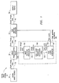
- FIGURE 1 is a block diagram illustrating a system utilizing a preferred embodiment of the tone mapping algorithm of the present invention
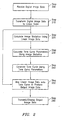
- FIGURE 2 is a flow chart illustrating the steps involved in the tone mapping algorithm shown in FIGURE 1 of the drawings;
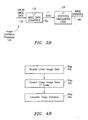
- FIGURES 3A-3C are block diagrams illustrating alternative embodiments for implementing the image statistics processor shown in FIGURE 1 of the drawings;
- FIGURES 4A-4C are flow charts illustrating the steps involved in each of the embodiments shown in FIGURES 3A-3C, respectively;
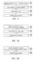
- FIGURE 5 is a flow chart illustrating the steps for calculating the slope parameter of the tone mapping algorithm of FIGURE 1;
- FIGURES 6A and 6B are flow charts illustrating alternative embodiments for calculating the shift parameter of the tone mapping algorithm of FIGURE 1;
- FIGURES 7A and 7B are block diagrams illustrating alternative embodiments for generating the tone curve of the tone mapping algorithm of the present invention.
- FIGURES 8A and 8B are flow charts illustrating the steps involved in the alternative embodiments shown in FIGURES 7A and 7B, respectively;
- FIGURE 9 is a graphical representation of a sample tone curve of the type generated by the tone mapping algorithm of the present invention.
- FIGURE 10 is a graphical representation of two pre-generated tone curves plotted on L* axes, in accordance with the embodiment shown in FIGURE 7B and 8B;
- FIGURE 11A is a graphical representation of output L *levels plotted as a function of the slope parameter, in accordance with the embodiment shown in FIGURE 7B and 8B;
- FIGURE 11B is a graphical representation of gamma corrected output levels plotted as a function of the slope parameter, in accordance with the embodiment shown in FIGURE 7B and 8B.
- the digital image system 10 can be any digital device, including, but not limited to, a digital camera, scanner, digital camcorder, printer capable of printing digital images or digital television.
- the algorithm 100 can be included within an image processing chip of the digital device, such as a low-end CMOS sensor chip, a CCD sensor chip or a separate image processing chip packaged together with the sensor chip, or within a software package (driver) associated with the digital device.
- the digital image system 10 can be a computer system having an image enhancement software package installed thereon in order to enhance tonal characteristics of digital images.
- the tone mapping algorithm 100 is simple and fast in terms of memory and processing time, and uses a global tone mapping method, with one tone curve for all color channels. It should be noted that the tone mapping algorithm 100 can be applied to both color images and monochrome images. The tone mapping algorithm 100 produces a smooth and consistent tone curve, with gentle curvature, which avoids the extreme contrast changes evident in some histogram equalization methods. In addition, the tone mapping algorithm 100 is ideal for video applications since the tone curve remains relatively stable from frame to frame by using an adaptive tone which is always sigmoidal in shape. Furthermore, the tone mapping algorithm 100 generates images that look pleasing to the user (in terms of brightness, contrast and color constancy) without requiring an estimation of the absolute luminance levels of the original image.
- the tone mapping algorithm 100 is based on perceptual preference guidelines, such as the preservation of general histogram shape at the middle range by using a centering function on L* n th and (100- n )th percentile values, an L * standard deviation of around 20 and a mean L * value of around 50. It should be understood that the L * scale is simply a transformation from a linear scale based on received linear image data. It should be noted that other perceptual preference guidelines can be used based on the requirements of the user or the specific digital image system 10 in which the tone mapping algorithm is implemented. In order to produce a tone mapping algorithm 100 that takes into consideration perceptual preferences and that complies with computation complexity constraints, a sigmoidal function tone mapping method is used, which will be described in more detail hereinbelow with respect to FIGURES 2-8.
- a digital image source 20 such as a digital image capture device or a digital image file, provides digital image data 25 associated with a digital image to a linear transformation device 30 (step 200), which transforms the digital image data 25 into linear image data 130 on a linear scale (step 210).
- a linear transformation device 30 provides digital image data 25 associated with a digital image to a linear transformation device 30 (step 200), which transforms the digital image data 25 into linear image data 130 on a linear scale (step 210).
- the original digital image data 25 may be on any scale.
- the digital image data 25 may already be on a linear scale, which obviates the need for the linear transformation device 30.
- This linear image data 130 is later used by a tone mapping operator 40 to map the linear image data 130 onto the luminance range of the output device 50 (step 250).
- the linear image data 130 is passed to an image statistics processor 120, which determines one or more image statistics 149 based on the original linear image data 130 (step 220). These image statistics 149 are used by tone curve parameter calculation logic 140, along with one or more predefined perceptual preferences in the calculation of two tone curve parameters 150, namely, the slope parameter and the shift parameter (step 230).
- the pre-defined perceptual preferences may be defined by an operator (e.g., a user or manufacturer of the digital image system 10).
- the shift parameter shifts the tone curve so that under or over-exposed images are brought closer to the right range.
- the slope parameter stretches or compresses the tone curve to achieve a desired histogram spread.
- tone curve generator 160 uses these two tone curve parameters 150 to generate a tone curve 170 for the image (step 240).
- the input value x in the sigmoidal function varies in the range [0, 100], because the tone curve 170 is generated on an L* scale, which is a measure of the brightness level of the image pixels and has values from 0 to 100.
- the L * scale is the preferred scale in the generation of the tone curve 170 for several reasons.
- a linear scale may be used by the tone curve generator 160 instead of the L * scale described herein.
- the sigmoidal tone curve 170 asymptotes to 0 and 100 at negative and positive infinity.
- the sigmoidal shaped tone curve 170 of the type shown in FIGURE 9 that is produced by the tone curve generator 160 has several properties that satisfy the constraints and perceptual preferences discussed above.
- the sigmoidal shaped tone curve 170 is mostly linear at the mid range, with saturation at the dark and bright end if the slope is high.
- a mostly linear segment at the mid range means that for most images, the bulk of the pixels will be mapped more or less linearly, thus preserving the shape of the original histogram.
- the parameters of the sigmoidal tone curve 170 can be set to achieve the desired L* standard deviation level.
- the sigmoidal function is smooth, with rather consistent curvature across different parameter settings (accelerating before the ⁇ point, decelerating after). Therefore, the sigmoidal function is unlikely to generate tone curves 170 that have wild bends and peaks.
- the received linear image data 130 is mapped onto this tone curve 170 by the tone mapping operator 40 to produce output image data 45 corresponding to the levels of the output device 50 (step 250).
- the output device 50 can be a display, printer or other image processing device. It should also be noted that additional processing may be performed on the output image data 45 prior to being sent to the output device 50 (step 260).
- the linear image data 130 (step 400) is passed to a histogram generator 122, which produces a histogram 145 (e.g., a table) describing the distribution of the digital values of the data 130 (step 405).
- a histogram generator 122 which produces a histogram 145 (e.g., a table) describing the distribution of the digital values of the data 130 (step 405).
- a histogram 145 e.g., a table
- red, blue and green values e.g., one of each for each pixel in the image.
- the histogram generator 122 determines a bin size (e.g., range of values, such as 0-10, 11-20, 21-30, etc.) and counts the number of occurrences of green pixel values in each bin. To create a graphical representation of the histogram, the data in each bin is plotted as a function of the bin centers (e.g., 5, 15, 25, etc.).
- a bin size e.g., range of values, such as 0-10, 11-20, 21-30, etc.
- the histogram bin center values 135 are transmitted to an L * bin center converter 124 to transform the linear bin center values 135 into L * bin center values 135a (step 410).
- the conversion is performed using equation (2) above, with Y being the bin center values, and Y n being the largest possible digital value for the pixel values.
- the L * bin center values 135a and the histogram 145, which includes the count of the number of values in each bin are transmitted to L * statistics calculation logic 128, which calculates the image statistics 149 (step 420) that are subsequently used in the calculation of the slope parameter ⁇ and the shift parameter ⁇ for the sigmoidal tone curve.
- the L * image statistics 149 used for calculation of the slope parameter ⁇ and the shift parameter ⁇ include the current L * standard deviation and either the current mean L * value or the L * percentile values of the histogram ( n th and (100- n )th percentiles).
- the L * percentile values of the histogram represent the end points of the histogram. Therefore, n is chosen to be relatively small (preferably less than 5). For example, if 5% of all L * pixel values have values less than 18, then the 5 th percentile is 18, thus the low end point would be 18. The high end point would then just be the L * value corresponding to the 95 th percentile (e.g., 95% of all L * pixel values have values lower than the high end point).
- the current L * standard deviation ⁇ current can be calculated from the histogram as follows: where B i s are histogram bin centers in L * values, n i is the pixel count in the ith bin of the histogram, n b is the number of histogram bins, n is the total number of pixels in the image, and L is the mean pixel L * value, which can also be calculated from the image histogram as follows:
- ⁇ current is calculated from the histogram on the green color plane only.
- the green channel is the color plane that approximately captures the luminance information.
- some combination of the RGB pixel values can be used instead to calculate the image L * standard deviation.
- the resulting tone curve should not vary significantly as long as the choice is a reasonable representation of the luminance.
- the image statistics 149 can be calculated from the image pixel values themselves. Therefore, when linear image data 130 arrives at the image statistics processor 120 (step 430), the linear image data 130 is converted into L * image values 130a by an L * image data converter 125 (step 435), and the L * image values 130a are passed onto the L * statistics calculation logic 128, where the image statistic 149 (e.g., current L * standard deviation and either the current mean L * value or the L * percentiles) are calculated (step 440).
- the current mean L * value can be calculated by taking the average of all of the L * image values.
- the histogram bin center values 135 can be converted into L * bin center values 135a prior to receiving the linear image data 130. Therefore, in this embodiment, once the histogram bin center values 135 are determined (step 450), the bin center values 135 are converted to L * bin center values 135a by the L * bin center converter 124 (step 455) and these L * bin center values 135a are stored in a memory 129 accessible to or within the image statistics processor 120 (the latter being illustrated) (step 460). As a further alternative, the conversion to L * bin center values 135a can be performed externally, and the L * bin center values 135a can be pre-loaded into the memory 129.
- the linear image data 130 arrives at the image statistics processor 120 (step 465), the linear image data 130 is sent to the histogram generator 122 (described above), which counts the number of pixel values in each bin (step 470). Once counted, the table 145, which includes the count of the number of pixel values in each bin is sent to the L * statistics calculation logic 128, which retrieves the L * bin center values 135a from the memory 129 (step 480) to calculate the image statistics 149 (step 485).
- the image statistics 149 e.g., L * standard deviation and mean L* value
- the image statistics 149 can be calculated with only simple addition, subtraction and multiplication.
- various perceptual preference guidelines can be used to produce an output image that is pleasing to the viewer.
- the perceptual preference guidelines can be chosen by the user or can be selected by the manufacturer of the specific digital image system in which the tone mapping algorithm is implemented. As an example, the following discussion is based on three preferred perceptual preferences, including the preservation of general histogram shape at the middle range, a desired L * standard deviation level of around 20 and a desired mean L * level of around 50. It should be understood that other perceptual preferences can be used instead of these preferred preferences.
- the current L * standard deviation calculated by the image statistics processor is transmitted to the tone curve parameter calculation logic (shown in FIGURE 1) (step 500).
- the desired L * standard deviation is pre-selected by the user or the manufacturer and stored within a memory (not shown) accessible to or within the tone curve parameter calculation logic (step 510).
- the desired L * standard deviation is chosen to be about 20. However, other values can be chosen, depending upon the requirements of the user or the manufacturer. Values greater than 20 produce a more contrasty image, while values less than 20 produce a less contrasty image.
- a default slope value is also pre-selected (step 520).
- the standard deviation can be changed from one value ( p ) to another value ( q ) by using a tone curve slope of q / p.
- the slope parameter ⁇ can be calculated based on the current L * standard deviation, the desired L* standard deviation and the default slope (step 530).
- the shift parameter ⁇ shifts the histogram to affect the general brightness of the output image.
- FIGURES 6A and 6B illustrate two such alternative embodiments for calculating the shift parameter ⁇ .
- the shift parameter ⁇ is calculated based on the mean L * value.
- the current mean L * value calculated by the image statistics processor is sent to the tone curve parameter calculation logic (shown in FIGURE 1) (step 600).
- the desired mean L * value is pre-selected by the user or the manufacturer and stored within a memory (not shown) accessible to or within the tone curve parameter calculation logic (step 610). Under some circumstances, however, this pre-selected desired mean L * value may be adjusted based on additional information about the image being processed. For example, if the content of the image is known to the image processor to be predominantly black objects, then the desired L * value can be adjusted to be lower than 50, to avoid over-brightening the image. Or, if the image data is known to have a high level of noise, the desired L * value can be biased to be closer to the original image mean L * value, to avoid amplification of the noise through tone mapping.
- the desired mean L * value of the whole image can be pre-selected to be around 50 (medium brightness).
- the desired mean L * value can be selected to be 50 in a certain area of the image.
- the L * mean value at the face area can be set to 50.
- the mean L * value of the center part of an image, or some other area of interest in the image can be brought to a level of around 50. This latter method of determining the shift parameter is more practical for a low cost imaging system. It should be understood that any other desired mean L * value can be used instead of 50.
- the shift parameter ⁇ is calculated based on the L * percentile values.
- the shift parameter can be determined by shifting the histogram to make it occupy as much of the output device dynamic range as possible, while bringing as little disturbance to the shape of the histogram as possible to avoid saturation of a lot of points at either end of the distribution. This is done by using a centering function in which the tone curve is centered at midway between the end points of the histogram. This is a conservative choice, typically resulting in only small changes to the mean luminance of the image if the original RGB histogram is somewhat "normal" (values are not concentrated on a small section of the full range).
- the combined histogram of RGB values is preferably used to determine the perceritiles, so that no color plane is ignored when calculating the shift of the tone curve. This is especially important for tone mapping performed on images with a strong color cast, to avoid color shifts after tone mapping.
- the first method ( ⁇ calculated from mean L * value) is simpler to implement, and works well on most indoor and outdoor images.
- mean L * value of the whole image When the mean L * value of the whole image is used as ⁇ , it tends to over-brighten night-time or dark images, i.e., images that are meant to have a low mean L * value, such as candlelight scenes.
- the second method (using the average of the top and bottom percentile of the histogram as ⁇ ) works better for dark images. It tends to change the image brightness less than the first method, so it is a more conservative method.
- the shift parameter ⁇ can deviate from 0.5.
- the extent the shift parameter ⁇ can deviate from 0.5.
- the value of the shift parameter can be limited depending on the mean pixel values of the original image.
- the shift parameter ⁇ is adjusted to deviate less from the midpoint 0.5 in order to reduce noise amplification.
- a series of ⁇ value upper limits T j are pre-selected, each corresponding to one mean level M j of the original image pixel values.
- the ⁇ value is limited to be at least T j , i.e., if the value calculated from Equation 7 or Equation 8 is less than T j , then ⁇ is set to be equal to T j .
- a series of lower limits T k can also be pre-selected, each corresponding to one mean pixel level M k .
- ⁇ is limited to be no greater than T k .
- FIGURES 7A and 7B there are illustrated alternative embodiments for implementing the tone curve generator 160 shown in FIGURE 1 of the drawings.
- the tone curve parameters 150 e.g., slope parameter ⁇ and the shift parameter ⁇
- these parameters are sent to the tone curve generator 160 (step 800).
- the sigmoidal tone curve 170 is generated by sigmoidal function logic 162 within the tone curve generator 160 using the received tone curve parameters 150 and equations (1) and (3) listed above (steps 805 and 810).
- the resulting tone curve 170 resembles the tone curve shown in FIGURE 9.
- the tone curve 170 shown in FIGURE 9 is capable of mapping L * image input values onto L * image output values for the appropriate output device.
- L * is not a commonly used scale in output devices
- the output digital image data is converted to linear form before conversion to the scale required by specific output devices.
- the Y-axis ( L * image output values) is converted by a Y-axis converter 164 from an L * scale to a linear scale (step 815), which is approximately a power of three transformation, as discussed above, to produce tone curve 170a.
- gamma correction is performed after mapping.
- gamma correction can either be performed separately after tone mapping, or can be combined with the tone mapping step.
- the gamma correction is performed together with tone mapping by applying gamma correction logic 166 to the Y-axis to produce tone curve 170b (step 820).
- the combined effect of linear transformation and gamma correction of the Y-axis (output) is a power of 3/ ⁇ , where y is the intended display gamma value, such as 2.4, if the output device is an sRGB (standard color space) display.
- the tone mapping is applied to linear RGB input pixel values (e.g., linear image data 130 is supplied by the linear transformation device 30 to the tone mapping operator 40 in FIGURE 1).
- the sigmoidal tone curve is generated assuming an L * scale on the X-axis, i.e., X-axis values uniformly sampled on the L * scale. Therefore, in order to properly map linear input values onto the tone curve, the tone curve's X-axis sampling has to be converted to be uniform on a linear scale for easy table lookup operation when applying the tone curve to images.
- tone curve 170c This is done by an X-axis converter 168 to produce tone curve 170c (step 825), using a simple linear interpolation process, which requires only arithmetic operations, as described above in connection with the Y-axis converter.
- This final tone curve 170c is used by the tone mapping operator (shown in FIGURE 1) to map the linear image data onto the luminance of the output device.
- ⁇ max and ⁇ min are set to be 2.5 and ⁇ max is set to be 6.5.
- sigmoidal function logic 162 can pre-calculate the two tone curves (step 855), one with a slope of 2.5 (curve P 1 ), which gives an almost linear tone curve (on the L * scale), and one with a steep slope of 6.5 (curve P 2 ), which gives a lot of contrast enhancement to the image.
- the two pre-generated tone curves are shown in FIGURE 10. It should be noted that the two curves are generated for a shift value ⁇ of 0. (The X-axis range for different ⁇ values are later determined by translating the X origin on the X-axis, as discussed hereinbelow.)
- the tone curve is generated by linear interpolation between P 1 and P 2 .
- the tone curve output L * values are plotted as a function of ⁇ for 11 different input pixel levels (represented by the 11 lines). As can be seen, the output L * values are close to linearly related to ⁇ .
- the tone mapping output is gamma-corrected linear RGB values ready for display on a screen. Therefore, as described above in connection with FIGURES 7A and 8A, the Y-axis of P 1 and P 2 158 may be converted to gamma-corrected linear RGB values (steps 860 and 865) by the Y-axis converter 164 and gamma correction logic 166 of the tone curve generator 160.
- the tone curve output P a ( x ) is gamma corrected linear RGB values
- the relationship with ⁇ is still quite linear, as shown in FIGURE 11B. Therefore, by pre-calculating P 1 and P 2 158 as gamma corrected pixel values, the interpolated tone values will be gamma corrected as well.
- tone curve calculation only requires the arithmetic operations used in interpolation (equation 9 above).
- the tone curve generator 160 receives the current slope parameter ⁇ current 150a and the current shift parameter ⁇ current 150b (step 875) from the tone curve parameter calculation logic (shown in FIGURE 1), calculation logic 163 within the tone curve generator 160 determines P a ( x ) 159 using the gamma corrected tone curves P 1 and P 2 158 and the current slope parameter 150a and equation 9 above (step 880). Thereafter, to select a section of P a ( x ), the current shift parameter 150b and P a ( x ) 159 are transmitted to shifting logic 165 within the tone curve generator 160 (step 885). Since the shift parameter 150b simply translates the tone curve on the X-axis, tone curves with different shift parameters can be obtained by translation on the X-axis of P a ( x ).
- the two ends of the tone curve need to be scaled to the full Y range. This again only requires arithmetic operations on each entry of the tone mapping table that was previously cut out from the pre-generated table.
- the X-axis converter 168 converts the X-axis from an L * scale to a linear scale (step 890) to produce the final tone curve 170.
- the translation of the tone curve can happen before or after the interpolation step required to get the correct slope by translating tone curves P 1 and P 2 158. For the least amount of computation, the translation is performed first, so that the interpolation only needs to be done on the "cut out" section of the pre-generated tone curves P 1 and P 2 158.
Landscapes
- Engineering & Computer Science (AREA)
- Physics & Mathematics (AREA)
- General Physics & Mathematics (AREA)
- Theoretical Computer Science (AREA)
- Multimedia (AREA)
- Signal Processing (AREA)
- Image Processing (AREA)
- Facsimile Image Signal Circuits (AREA)
- Color Image Communication Systems (AREA)
Abstract
Description


Claims (20)
- A digital image system (100) capable of receiving digital image data (25) representing at least part of a digital image and mapping said digital image data (25) onto the range of an output device (50), said digital image system (100) comprising:an image statistics processor (120) capable of calculating at least one current image statistic (149) based on said digital image data (25);calculation logic (140) connected to receive said at least one current image statistic (149) from said image statistics processor (120) and further being capable of calculating at least one tone curve parameter (150) based on said at least one current image. statistic (149) and at least one perceptual preference associated with said digital image system (100); anda tone curve generator (160) connected to receive said at least one tone curve parameter (150) from said calculation logic (140) and further being capable of generating a tone curve (170) using said at least one tone curve parameter (150) and a sigmoidal function, said tone curve (170) being used to map said digital image data (25) onto the range of said output device (50).
- The system (100) of Claim 1, further comprising:a linear transformation device (30) connected to receive said digital image data (25), convert said digital image data (25) into linear image data (130) and transmit said linear image data (130) to said image statistics processor (120), said image statistics processor (120) using said linear image data (130) in calculating said at least one current image statistic (149).
- The system (100) of Claim 1 or 2, wherein said image statistics processor comprises:a histogram generator (122) connected to receive said linear image data (130) and generate a histogram (145) of the pixel values represented by said linear image data (135), said histogram (145) containing a plurality of bins representing respective ranges of pixel values and a count of the number of pixel values represented by said linear image data (130) within each of said plurality of bins;a converter (124) capable of converting a bin center value (135) for each of said bins associated with said histogram (145) from a linear scale to an L * scale to produce a plurality of L * bin center values (135a); andstatistics calculation logic (128) connected to receive said count from said histogram generator (122) and said plurality of L * bin center values (135a) from said converter (124) and calculate said at least one current image statistic (149) using said count and said plurality of L * bin center values (135a).
- The system (100) of Claim 3, further comprising:a memory (129) for storing said plurality of L * bin center values (135a) prior to said histogram (145) being generated, said statistics calculation logic (128) retrieving said plurality of L * bin center values (135a) in response to receiving said count.
- The system (100) of one of the preceding Claims, wherein said at least one tone curve parameter (150) includes a slope parameter and a shift parameter and wherein said at least one current image statistic (149) includes a current L* standard deviation and one of a current mean L * value or low and high L * percentile values.
- The system (100) of Claim 5, wherein said at least one perceptual preference includes a desired L * standard deviation and one of a desired mean L * value or a centering function, said slope parameter being calculated using said current L * standard deviation and said desired L * standard deviation, said shift parameter being calculated using either said current mean L * value and said desired mean L * value or said low and high L * percentile values and said centering function.
- The system (100) of Claim 6, further comprising:an upper pre-selected mean L * value and an associated upper pre-selected shift value, said shift parameter being set to said upper pre-selected shift value when said current mean L * value is less than said upper pre-selected mean L * value and said calculated shift parameter is less than said upper pre-selected shift value; anda lower pre-selected mean L * value and an associated lower pre-selected shift value, said shift parameter being set to said lower pre-selected shift value when said current mean L * value is greater than said lower pre-selected mean L * value and said calculated shift parameter is greater than said lower pre-selected shift value.
- The system (100) of one of Claims 5 - 7, further comprising a memory (169) for storing first and second pre-calculated tone curves (158) generated by said tone curve generator (160) prior to said digital image system (100) receiving said digital image data (25), said first pre-calculated tone curve having a minimum slope and said second pre-calculated tone curve having a maximum slope.
- The system of Claim 8, wherein said tone curve generator comprises:calculation logic (163) connected to receive said slope parameter (150a) and said first and second pre-calculated tone curves (158), said calculation logic (163) being further capable of interpolating between said first and second pre-calculated tone curves (158) using said slope parameter (150a) to obtain an initial tone curve (159); andshifting logic (165) connected to receive said initial tone curve (159) and said shift parameter (150b), said shifting logic (165) being further capable of shifting said initial tone curve (159) on the X-axis using said shift parameter (150b) to produce said tone curve (170) used in mapping said digital image data (25) onto the range of said output device (50).
- The system of one of the preceding Claims, wherein said tone curve generator further comprises:gamma correction logic (166) for applying gamma correction to the Y-axis of said tone curve (170); anda converter (168) for converting theX-axis of said tone curve (170) to the scale of said digital image data (25).
- A method for mapping digital image data (25) representing at least part of a digital image onto the range of an output device (50), said method comprising:receiving said digital image data (25) at a digital image system (100);calculating at least one current image statistic (149) based on said digital image data (25);calculating at least one tone curve parameter (150) based on said at least one current image statistic (149) and at least one perceptual preference; andgenerating a tone curve (170) using said at least one tone curve parameter (150) and a sigmoidal function, and using said tone curve (170) to map said digital image data (25) onto the range of said output device (50).
- The method of Claim 11, wherein said step of calculating said at least one current image statistic (149) further comprises:converting said digital image data (25) into linear image data (130); andcalculating said at least one current image statistic (149) using said linear image data (130).
- The method of Claim 12, wherein calculating said at least one current image statistic (149) further comprises:generating a histogram (145) of the pixel values represented by said linear image data (130), said histogram (145) containing a plurality of bins representing respective ranges of pixel values and a count of the number of pixel values represented by said linear image data (130) within each of said plurality of bins;converting a bin center value (135) for each of said bins associated with said histogram (145) from a linear scale to an L * scale to produce a plurality of L * bin center values (135a); andcalculating said at least one current image statistic (149) using said count and said plurality of L * bin center values (135a).
- The method of Claim 13, wherein converting said bin centers further comprises:converting said bin center values (135) to produce a plurality of L * bin center values (135a) prior to said step of generating; andstoring said plurality of L * bin center values (135a) within a memory (129).
- The method of one of Claims 11 - 14, wherein said at least one tone curve parameter (150) includes a slope parameter and a shift parameter and wherein said at least one current image statistic (149) includes a current L * standard deviation and one of a current mean L * value or low and high L * percentile values.
- The method of Claim 15, wherein said at least one perceptual preference includes a desired L * standard deviation and one of a desired mean L * value or a centering function, calculating said at least one tone curve parameter (150) further comprising:calculating said slope parameter using said current L * standard deviation and said desired L * standard deviation; andcalculating said shift parameter using either said current mean L * value and said desired mean L * value or said low and high L * percentile values and said centering function.
- The method of Claim 16, wherein calculating said at least one tone curve parameter (150) further comprises:setting said shift parameter to be equal to an upper pre-selected shift value when said current mean L * value is less than an upper pre-selected mean L * value associated with said upper pre-selected shift value and said calculated shift parameter is less than said upper pre-selected shift value; andsetting said shift parameter to be equal to a lower pre-selected shift value when said current mean L * value is greater than a lower pre-selected mean L * value associated with said lower pre-selected shift value and said calculated shift parameter is greater than said lower pre-selected shift value.
- The method of one of Claims 15 - 17, wherein generating further comprises:generating first and second pre-calculated tone curves (158) prior to said step of receiving said digital image data (25), said first pre-calculated tone curve having a minimum slope and said second pre-calculated tone curve having a maximum slope.
- The method of Claim 18, wherein generating said tone curve (170) used in mapping said digital image data (25) onto the range of said output device (50) comprises:interpolating between said first and second pre-calculated tone curves (158) using said slope parameter (150a) to obtain an initial tone curve (159); andshifting said initial tone curve (159) on the X-axis using said shift parameter (150b) to produce said tone curve (170) used in mapping said digital image data (25) onto the range of said output device (50).
- The method of one of Claims 11 - 19, wherein generating said tone curve (170) comprises:applying gamma correction to the Y-axis of said tone curve (170); andconverting the X-axis of said tone curve (170) to the scale of said digital image data (25).
Applications Claiming Priority (2)
| Application Number | Priority Date | Filing Date | Title |
|---|---|---|---|
| US839335 | 2001-04-20 | ||
| US09/839,335 US7023580B2 (en) | 2001-04-20 | 2001-04-20 | System and method for digital image tone mapping using an adaptive sigmoidal function based on perceptual preference guidelines |
Publications (3)
| Publication Number | Publication Date |
|---|---|
| EP1302898A2 true EP1302898A2 (en) | 2003-04-16 |
| EP1302898A3 EP1302898A3 (en) | 2005-01-19 |
| EP1302898B1 EP1302898B1 (en) | 2006-10-04 |
Family
ID=25279458
Family Applications (1)
| Application Number | Title | Priority Date | Filing Date |
|---|---|---|---|
| EP02000691A Expired - Lifetime EP1302898B1 (en) | 2001-04-20 | 2002-01-11 | System and method for digital image tone mapping using an adaptive sigmoidal function based on perceptual preference guidelines |
Country Status (4)
| Country | Link |
|---|---|
| US (1) | US7023580B2 (en) |
| EP (1) | EP1302898B1 (en) |
| JP (1) | JP2003044846A (en) |
| DE (1) | DE60215097T2 (en) |
Cited By (7)
| Publication number | Priority date | Publication date | Assignee | Title |
|---|---|---|---|---|
| EP1667064A4 (en) * | 2003-09-11 | 2009-06-10 | Panasonic Corp | VISUAL PROCESSING DEVICE, HABITUAL PROCESSING METHOD, VISUAL PROCESSING PROGRAM, AND SEMICONDUCTOR DEVICE |
| US7860339B2 (en) | 2003-09-11 | 2010-12-28 | Panasonic Corporation | Visual processing device, visual processing method, visual processing program, intergrated circuit, display device, image-capturing device, and portable information terminal |
| US8958638B2 (en) | 2012-06-10 | 2015-02-17 | Apple Inc. | Method and system for multi-stage auto-enhancement of photographs |
| CN105324997A (en) * | 2013-06-17 | 2016-02-10 | 杜比实验室特许公司 | Adaptive Shaping for Layered Coding of Enhanced Dynamic Range Signals |
| US9536290B2 (en) | 2012-06-10 | 2017-01-03 | Apple Inc. | Tempered auto-adjusting, image-editing operation |
| US10225485B1 (en) | 2014-10-12 | 2019-03-05 | Oliver Markus Haynold | Method and apparatus for accelerated tonemapping |
| US11290612B1 (en) | 2014-08-21 | 2022-03-29 | Oliver Markus Haynold | Long-exposure camera |
Families Citing this family (83)
| Publication number | Priority date | Publication date | Assignee | Title |
|---|---|---|---|---|
| JP4210026B2 (en) * | 1999-09-30 | 2009-01-14 | セイコーエプソン株式会社 | COLOR CORRECTION DEVICE, COLOR CORRECTION METHOD, AND RECORDING MEDIUM CONTAINING COLOR CORRECTION CONTROL PROGRAM |
| US6873729B2 (en) * | 2000-07-14 | 2005-03-29 | Ricoh Company, Ltd. | Method, apparatus and computer program product for processing image data |
| ITTO20011080A1 (en) * | 2001-11-19 | 2003-05-19 | Olivetti Tecnost Spa | ,, METHOD AND DEVICE FOR DETERMINING A CHROMATIC DOMINANT IN AN IMAGE ,, |
| US20030160800A1 (en) * | 2002-02-22 | 2003-08-28 | Agfa-Gevaert | Multiscale gradation processing method |
| US7221807B2 (en) * | 2002-03-29 | 2007-05-22 | Sharp Laboratories Of America, Inc. | Methods and systems for digital image characteristic adjustment using a neural network |
| US20050008262A1 (en) * | 2003-06-03 | 2005-01-13 | Konica Minolta Medical & Graphic, Inc. | Medical image system, and medical image processing method |
| US7768500B2 (en) * | 2003-06-16 | 2010-08-03 | Humanscale Corporation | Ergonomic pointing device |
| EP1667065B1 (en) * | 2003-09-11 | 2018-06-06 | Panasonic Intellectual Property Corporation of America | Visual processing apparatus, visual processing method, visual processing program, and semiconductor device |
| US7512286B2 (en) * | 2003-10-27 | 2009-03-31 | Hewlett-Packard Development Company, L.P. | Assessing image quality |
| JP2005141527A (en) * | 2003-11-07 | 2005-06-02 | Sony Corp | Image processing apparatus, image processing method, and computer program |
| JP4610182B2 (en) * | 2003-12-05 | 2011-01-12 | 株式会社日立ハイテクノロジーズ | Scanning electron microscope |
| US7557799B2 (en) * | 2004-06-17 | 2009-07-07 | Avago Technologies Ecbu Ip (Singapore) Pte. Ltd. | System for determining pointer position, movement, and angle |
| US7386155B2 (en) * | 2004-11-22 | 2008-06-10 | Carestream Health, Inc. | Transforming visual preference terminology for radiographic images |
| JP4359844B2 (en) * | 2004-11-24 | 2009-11-11 | ノーリツ鋼機株式会社 | Film base density detection method and apparatus |
| US7522781B2 (en) * | 2005-02-11 | 2009-04-21 | Samsung Electronics Co., Ltd. | Method and apparatus for image processing based on a mapping function |
| JP2006289951A (en) * | 2005-03-16 | 2006-10-26 | Seiko Epson Corp | Printing method, printing apparatus, printing program, computer-readable recording medium, printing apparatus control program, printing apparatus control method, printing data generation apparatus, printing data generation program, and printing data generation method |
| US7433514B2 (en) * | 2005-07-13 | 2008-10-07 | Canon Kabushiki Kaisha | Tone mapping of high dynamic range images |
| CN100407765C (en) * | 2005-09-07 | 2008-07-30 | 逐点半导体(上海)有限公司 | Image contrast enhancement device and enhancement method |
| US7684639B2 (en) * | 2005-10-20 | 2010-03-23 | Sharp Laboratories Of America, Inc. | Methods and systems for automatic digital image enhancement |
| US7684640B2 (en) * | 2005-10-20 | 2010-03-23 | Sharp Laboratories Of America, Inc. | Methods and systems for automatic digital image enhancement with local adjustment |
| US8194997B2 (en) * | 2006-03-24 | 2012-06-05 | Sharp Laboratories Of America, Inc. | Methods and systems for tone mapping messaging |
| US7830418B2 (en) * | 2006-04-28 | 2010-11-09 | Hewlett-Packard Development Company, L.P. | Perceptually-derived red-eye correction |
| JP4997846B2 (en) * | 2006-06-30 | 2012-08-08 | ブラザー工業株式会社 | Image processing program and image processing apparatus |
| US7822289B2 (en) * | 2006-07-25 | 2010-10-26 | Microsoft Corporation | Locally adapted hierarchical basis preconditioning |
| KR100843088B1 (en) * | 2006-08-16 | 2008-07-02 | 삼성전자주식회사 | Apparatus and method for outputting image of wide color gamut |
| US7714903B2 (en) * | 2006-08-29 | 2010-05-11 | Zoran Corporation | Wide dynamic range image capturing system method and apparatus |
| US8687087B2 (en) * | 2006-08-29 | 2014-04-01 | Csr Technology Inc. | Digital camera with selectively increased dynamic range by control of parameters during image acquisition |
| JP4848903B2 (en) * | 2006-09-11 | 2011-12-28 | 富士ゼロックス株式会社 | Color processing apparatus, color processing method, and program |
| WO2008064349A1 (en) * | 2006-11-22 | 2008-05-29 | Nik Software, Inc. | Method for dynamic range editing |
| TW200828210A (en) * | 2006-12-18 | 2008-07-01 | Wistron Corp | Method and device of rapidly building a gray-level and brightness curve of displayer |
| US8355595B2 (en) * | 2007-05-15 | 2013-01-15 | Xerox Corporation | Contrast enhancement methods and apparatuses |
| US7983502B2 (en) * | 2007-08-06 | 2011-07-19 | Microsoft Corporation | Viewing wide angle images using dynamic tone mapping |
| US8411983B2 (en) * | 2007-08-31 | 2013-04-02 | Ati Technologies Ulc | Method and apparatus for producing a contrast enhanced image |
| US20090317017A1 (en) * | 2008-06-20 | 2009-12-24 | The Hong Kong University Of Science And Technology | Image characteristic oriented tone mapping for high dynamic range images |
| US8111935B2 (en) * | 2007-10-03 | 2012-02-07 | Himax Technologies Limited | Image processing methods and image processing apparatus utilizing the same |
| US8107756B2 (en) * | 2007-10-11 | 2012-01-31 | Himax Technologies Limited | Digital image tone remapping method and apparatus |
| US8130236B2 (en) * | 2008-02-05 | 2012-03-06 | Aptina Imaging Corporation | Systems and methods to achieve preferred imager color reproduction |
| US8311361B2 (en) * | 2008-08-21 | 2012-11-13 | Hong Kong Applied Science and Technology Research Institute Company Limited | Digital image enhancement |
| JP5756404B2 (en) * | 2008-09-30 | 2015-07-29 | ドルビー ラボラトリーズ ライセンシング コーポレイション | System and method for adaptive gamma application in image processing for high brightness and high dynamic range displays and computer readable medium |
| US20100149207A1 (en) * | 2008-11-21 | 2010-06-17 | Madden Thomas E | Grayscale characteristic for color display device |
| US8125569B2 (en) * | 2008-12-03 | 2012-02-28 | Sony Corporation | Dynamic contrast on displays using average picture level and histogram analysis |
| US8363131B2 (en) * | 2009-01-15 | 2013-01-29 | Aptina Imaging Corporation | Apparatus and method for local contrast enhanced tone mapping |
| US8290295B2 (en) * | 2009-03-03 | 2012-10-16 | Microsoft Corporation | Multi-modal tone-mapping of images |
| JP5430218B2 (en) * | 2009-05-07 | 2014-02-26 | キヤノン株式会社 | Image processing apparatus and image processing method |
| US8537175B1 (en) * | 2009-05-07 | 2013-09-17 | Google Inc. | Video enhancement for large scale applications |
| US8358351B2 (en) * | 2009-06-05 | 2013-01-22 | Apple Inc. | Automatic tone mapping for cameras |
| JP2011005050A (en) * | 2009-06-26 | 2011-01-13 | Canon Inc | Image processing method and image processing apparatus |
| US8457398B2 (en) * | 2009-10-27 | 2013-06-04 | Himax Media Solutions, Inc. | Image enhancement method and apparatuses utilizing the same |
| EP2355037A1 (en) * | 2009-12-18 | 2011-08-10 | Nxp B.V. | Method of and system for determining an average colour value for pixels |
| JP5537995B2 (en) * | 2010-03-01 | 2014-07-02 | 東芝テリー株式会社 | Image processing apparatus and image processing program |
| CN102783132B (en) * | 2010-03-03 | 2016-08-03 | 皇家飞利浦电子股份有限公司 | Apparatus and method for defining color states |
| US8280184B2 (en) * | 2010-04-01 | 2012-10-02 | Himax Media Solutions, Inc. | Image enhancement method and apparatuses utilizing the same |
| US8314847B2 (en) * | 2010-05-25 | 2012-11-20 | Apple Inc. | Automatic tone mapping curve generation based on dynamically stretched image histogram distribution |
| US8538148B2 (en) * | 2010-09-24 | 2013-09-17 | Intel Corporation | Brightness enhancement method, system and apparatus for low power architectures |
| US20120114265A1 (en) * | 2010-11-05 | 2012-05-10 | Toshiba Tec Kabushiki Kaisha | Image Contrast Enhancement |
| PT3742715T (en) * | 2011-05-27 | 2024-10-21 | Dolby Laboratories Licensing Corp | Scalable systems for controlling color management comprising varying levels of metadata |
| US8988552B2 (en) | 2011-09-26 | 2015-03-24 | Dolby Laboratories Licensing Corporation | Image formats and related methods and apparatuses |
| KR20130035019A (en) * | 2011-09-29 | 2013-04-08 | 삼성전기주식회사 | Image processing device and method for processing image |
| US10242650B2 (en) | 2011-12-06 | 2019-03-26 | Dolby Laboratories Licensing Corporation | Perceptual luminance nonlinearity-based image data exchange across different display capabilities |
| ES2995169T3 (en) | 2011-12-06 | 2025-02-07 | Dolby Laboratories Licensing Corp | Method of improving the perceptual luminance nonlinearity-based image data exchange across different display capabilities |
| US9621762B2 (en) * | 2012-01-09 | 2017-04-11 | Ricoh Company, Ltd. | Halftone calibration mechanism employing an ink model |
| KR101354767B1 (en) * | 2012-06-07 | 2014-01-23 | 엘에스산전 주식회사 | Apparatus and method for controlling output |
| WO2014043005A1 (en) * | 2012-09-12 | 2014-03-20 | Dolby Laboratories Licensing Corporation | Display management for images with enhanced dynamic range |
| US9955084B1 (en) | 2013-05-23 | 2018-04-24 | Oliver Markus Haynold | HDR video camera |
| US20140368531A1 (en) * | 2013-06-12 | 2014-12-18 | Synaptics Incorporated | Dynamic contrast enhancement using dithered gamma remapping |
| JP2015011585A (en) | 2013-06-28 | 2015-01-19 | 株式会社リコー | Image processing apparatus, image forming apparatus, image forming system, image processing method, and program |
| US9275445B2 (en) | 2013-08-26 | 2016-03-01 | Disney Enterprises, Inc. | High dynamic range and tone mapping imaging techniques |
| GB201410635D0 (en) * | 2014-06-13 | 2014-07-30 | Univ Bangor | Improvements in and relating to the display of images |
| US9418311B2 (en) * | 2014-09-04 | 2016-08-16 | Apple Inc. | Multi-scale tone mapping |
| KR102631484B1 (en) | 2015-01-27 | 2024-01-30 | 인터디지털 매디슨 페턴트 홀딩스 에스에이에스 | Methods, systems and devices for electro-optical and optical-electrical conversion of images and videos |
| WO2016153896A1 (en) * | 2015-03-20 | 2016-09-29 | Dolby Laboratories Licensing Corporation | Signal reshaping approximation |
| US10885614B2 (en) | 2015-08-19 | 2021-01-05 | Samsung Electronics Co., Ltd. | Electronic device performing image conversion, and method thereof |
| EP3369241B1 (en) | 2015-10-28 | 2020-12-09 | InterDigital VC Holdings, Inc. | Method and device for selecting a process to be applied on video data from a set of candidate processes driven by a common set of information data |
| US10726619B2 (en) | 2015-10-29 | 2020-07-28 | Sony Interactive Entertainment Inc. | Foveated geometry tessellation |
| US10442211B2 (en) | 2017-02-21 | 2019-10-15 | Ricoh Company, Ltd. | Dual pass uniformity printing compensation mechanism |
| CN107316279B (en) * | 2017-05-23 | 2019-11-22 | 天津大学 | Low-light Image Enhancement Method Based on Tone Mapping and Regularization Model |
| CN108564633B (en) * | 2018-01-05 | 2022-03-22 | 珠海市杰理科技股份有限公司 | Gray scale image compression method and device and computer equipment |
| CN112514359B (en) * | 2018-06-18 | 2022-02-18 | 杜比实验室特许公司 | Image capture method, apparatus, machine-readable storage device |
| WO2021020627A1 (en) * | 2019-07-31 | 2021-02-04 | 엘지전자 주식회사 | Display device and operation method thereof |
| US11430093B2 (en) * | 2019-10-01 | 2022-08-30 | Microsoft Technology Licensing, Llc | Face-based tone curve adjustment |
| CN110890063B (en) * | 2019-11-22 | 2021-10-08 | 深圳市华星光电半导体显示技术有限公司 | Method and device for reducing power consumption of display panel |
| CN115804080B (en) | 2020-07-13 | 2025-01-03 | 高通股份有限公司 | Correction of color-tinted pixels captured in low-light conditions |
| CN117078676B (en) * | 2023-10-16 | 2024-01-12 | 青岛盛鑫达机械有限公司 | Breaking hammer shell visual detection method based on image processing |
Family Cites Families (11)
| Publication number | Priority date | Publication date | Assignee | Title |
|---|---|---|---|---|
| US4975970A (en) | 1987-03-18 | 1990-12-04 | General Electric Company | Image display having automatic image adjustment |
| DE69130275T2 (en) | 1990-07-31 | 1999-04-08 | Canon K.K., Tokio/Tokyo | Image processing method and apparatus |
| WO1996009717A1 (en) * | 1994-09-19 | 1996-03-28 | Apple Computer, Inc. | Generation of tone reproduction curves using psychophysical data |
| US5581370A (en) * | 1995-06-05 | 1996-12-03 | Xerox Corporation | Image-dependent automatic area of interest enhancement |
| US5991456A (en) | 1996-05-29 | 1999-11-23 | Science And Technology Corporation | Method of improving a digital image |
| US5822453A (en) | 1996-12-10 | 1998-10-13 | Eastman Kodak Company | Method for estimating and adjusting digital image contrast |
| JP3639405B2 (en) | 1997-03-07 | 2005-04-20 | 東洋インキ製造株式会社 | Color gamut compression method and apparatus |
| US6198842B1 (en) | 1997-06-19 | 2001-03-06 | International Business Machines Corporation | Multi-spectral image compression with bounded loss |
| US6393148B1 (en) * | 1999-05-13 | 2002-05-21 | Hewlett-Packard Company | Contrast enhancement of an image using luminance and RGB statistical metrics |
| US6822762B2 (en) * | 2000-03-31 | 2004-11-23 | Hewlett-Packard Development Company, L.P. | Local color correction |
| US6826310B2 (en) * | 2001-07-06 | 2004-11-30 | Jasc Software, Inc. | Automatic contrast enhancement |
-
2001
- 2001-04-20 US US09/839,335 patent/US7023580B2/en not_active Expired - Fee Related
-
2002
- 2002-01-11 DE DE60215097T patent/DE60215097T2/en not_active Expired - Fee Related
- 2002-01-11 EP EP02000691A patent/EP1302898B1/en not_active Expired - Lifetime
- 2002-04-16 JP JP2002113090A patent/JP2003044846A/en not_active Withdrawn
Cited By (13)
| Publication number | Priority date | Publication date | Assignee | Title |
|---|---|---|---|---|
| EP1667064A4 (en) * | 2003-09-11 | 2009-06-10 | Panasonic Corp | VISUAL PROCESSING DEVICE, HABITUAL PROCESSING METHOD, VISUAL PROCESSING PROGRAM, AND SEMICONDUCTOR DEVICE |
| US7783126B2 (en) | 2003-09-11 | 2010-08-24 | Panasonic Corporation | Visual processing device, visual processing method, visual processing program, and semiconductor device |
| US7860339B2 (en) | 2003-09-11 | 2010-12-28 | Panasonic Corporation | Visual processing device, visual processing method, visual processing program, intergrated circuit, display device, image-capturing device, and portable information terminal |
| US7945115B2 (en) | 2003-09-11 | 2011-05-17 | Panasonic Corporation | Visual processing device, visual processing method, visual processing program, and semiconductor device |
| US8165417B2 (en) | 2003-09-11 | 2012-04-24 | Panasonic Corporation | Visual processing device, visual processing method, visual processing program, integrated circuit, display device, image-capturing device, and portable information terminal |
| US8983186B2 (en) | 2012-06-10 | 2015-03-17 | Apple Inc. | Method and system for auto-enhancing photographs with shadow lift adjustments |
| US8958638B2 (en) | 2012-06-10 | 2015-02-17 | Apple Inc. | Method and system for multi-stage auto-enhancement of photographs |
| US9536290B2 (en) | 2012-06-10 | 2017-01-03 | Apple Inc. | Tempered auto-adjusting, image-editing operation |
| CN105324997A (en) * | 2013-06-17 | 2016-02-10 | 杜比实验室特许公司 | Adaptive Shaping for Layered Coding of Enhanced Dynamic Range Signals |
| CN105324997B (en) * | 2013-06-17 | 2018-06-29 | 杜比实验室特许公司 | Adaptive Shaping for Layered Coding of Enhanced Dynamic Range Signals |
| US11290612B1 (en) | 2014-08-21 | 2022-03-29 | Oliver Markus Haynold | Long-exposure camera |
| US10225485B1 (en) | 2014-10-12 | 2019-03-05 | Oliver Markus Haynold | Method and apparatus for accelerated tonemapping |
| US10868969B1 (en) | 2014-10-12 | 2020-12-15 | Promanthan Brains Llc, Series Gaze Only | Method and apparatus for accelerated tonemapping and display |
Also Published As
| Publication number | Publication date |
|---|---|
| DE60215097T2 (en) | 2007-04-05 |
| US20020171852A1 (en) | 2002-11-21 |
| US7023580B2 (en) | 2006-04-04 |
| EP1302898B1 (en) | 2006-10-04 |
| JP2003044846A (en) | 2003-02-14 |
| EP1302898A3 (en) | 2005-01-19 |
| DE60215097D1 (en) | 2006-11-16 |
Similar Documents
| Publication | Publication Date | Title |
|---|---|---|
| EP1302898B1 (en) | System and method for digital image tone mapping using an adaptive sigmoidal function based on perceptual preference guidelines | |
| US12238427B2 (en) | Global tone mapping | |
| JP5100565B2 (en) | Image processing apparatus and image processing method | |
| KR101051604B1 (en) | Image processing apparatus and method | |
| US10469760B2 (en) | High dynamic range imaging | |
| US6825884B1 (en) | Imaging processing apparatus for generating a wide dynamic range image | |
| JP5105209B2 (en) | Image processing apparatus and method, program, and recording medium | |
| JP3759761B2 (en) | Method and apparatus for changing sharpness | |
| US8665348B2 (en) | Image processing apparatus and method using forward and inverse local adaptation processing and dynamic range processing | |
| JP2000228747A (en) | Image processing device | |
| JP5901667B2 (en) | Image processing apparatus and method, image processing program, and imaging apparatus | |
| JP6004757B2 (en) | Image processing apparatus and image processing method | |
| JP2020145553A (en) | Image processing equipment, image processing methods, and programs | |
| CN106575434A (en) | Image processing device, image capturing device, image processing method, and program | |
| US7755670B2 (en) | Tone-conversion device for image, program, electronic camera, and tone-conversion method | |
| JP2018112936A (en) | HDR image processing apparatus and method | |
| JP4479527B2 (en) | Image processing method, image processing apparatus, image processing program, and electronic camera | |
| JP6335614B2 (en) | Image processing apparatus, control method thereof, and program | |
| JP2002223355A (en) | Image processing apparatus and recording medium recording image processing program | |
| JP5225491B2 (en) | Image processing apparatus and image processing method | |
| JP4992379B2 (en) | Image gradation conversion apparatus, program, electronic camera, and method thereof | |
| JP2012044560A (en) | Image processing apparatus, image processing method, and imaging apparatus | |
| JP5627730B2 (en) | Image processing apparatus and image processing method | |
| KR101073497B1 (en) | Apparatus for enhancing image and method therefor | |
| Kyung et al. | Improved color reproduction based on CIELAB color space in integrated multi-scale retinex |
Legal Events
| Date | Code | Title | Description |
|---|---|---|---|
| PUAI | Public reference made under article 153(3) epc to a published international application that has entered the european phase |
Free format text: ORIGINAL CODE: 0009012 |
|
| AK | Designated contracting states |
Designated state(s): AT BE CH CY DE DK ES FI FR GB GR IE IT LI LU MC NL PT SE TR |
|
| AX | Request for extension of the european patent |
Extension state: AL LT LV MK RO SI |
|
| PUAL | Search report despatched |
Free format text: ORIGINAL CODE: 0009013 |
|
| AK | Designated contracting states |
Kind code of ref document: A3 Designated state(s): AT BE CH CY DE DK ES FI FR GB GR IE IT LI LU MC NL PT SE TR |
|
| AX | Request for extension of the european patent |
Extension state: AL LT LV MK RO SI |
|
| 17P | Request for examination filed |
Effective date: 20050210 |
|
| 17Q | First examination report despatched |
Effective date: 20050705 |
|
| AKX | Designation fees paid |
Designated state(s): DE FR GB |
|
| GRAP | Despatch of communication of intention to grant a patent |
Free format text: ORIGINAL CODE: EPIDOSNIGR1 |
|
| GRAS | Grant fee paid |
Free format text: ORIGINAL CODE: EPIDOSNIGR3 |
|
| GRAA | (expected) grant |
Free format text: ORIGINAL CODE: 0009210 |
|
| AK | Designated contracting states |
Kind code of ref document: B1 Designated state(s): DE FR GB |
|
| REG | Reference to a national code |
Ref country code: GB Ref legal event code: FG4D |
|
| REF | Corresponds to: |
Ref document number: 60215097 Country of ref document: DE Date of ref document: 20061116 Kind code of ref document: P |
|
| RAP2 | Party data changed (patent owner data changed or rights of a patent transferred) |
Owner name: AGILENT TECHNOLOGIES, INC. |
|
| ET | Fr: translation filed | ||
| PGFP | Annual fee paid to national office [announced via postgrant information from national office to epo] |
Ref country code: DE Payment date: 20070712 Year of fee payment: 6 |
|
| PLBE | No opposition filed within time limit |
Free format text: ORIGINAL CODE: 0009261 |
|
| STAA | Information on the status of an ep patent application or granted ep patent |
Free format text: STATUS: NO OPPOSITION FILED WITHIN TIME LIMIT |
|
| 26N | No opposition filed |
Effective date: 20070705 |
|
| GBPC | Gb: european patent ceased through non-payment of renewal fee |
Effective date: 20070111 |
|
| REG | Reference to a national code |
Ref country code: FR Ref legal event code: ST Effective date: 20070930 |
|
| PG25 | Lapsed in a contracting state [announced via postgrant information from national office to epo] |
Ref country code: GB Free format text: LAPSE BECAUSE OF NON-PAYMENT OF DUE FEES Effective date: 20070111 |
|
| PG25 | Lapsed in a contracting state [announced via postgrant information from national office to epo] |
Ref country code: FR Free format text: LAPSE BECAUSE OF NON-PAYMENT OF DUE FEES Effective date: 20070131 |
|
| PG25 | Lapsed in a contracting state [announced via postgrant information from national office to epo] |
Ref country code: DE Free format text: LAPSE BECAUSE OF NON-PAYMENT OF DUE FEES Effective date: 20080801 |