EP1302817A2 - Fixing device - Google Patents
Fixing device Download PDFInfo
- Publication number
- EP1302817A2 EP1302817A2 EP02022697A EP02022697A EP1302817A2 EP 1302817 A2 EP1302817 A2 EP 1302817A2 EP 02022697 A EP02022697 A EP 02022697A EP 02022697 A EP02022697 A EP 02022697A EP 1302817 A2 EP1302817 A2 EP 1302817A2
- Authority
- EP
- European Patent Office
- Prior art keywords
- electric power
- power supply
- heater
- temperature
- waves
- Prior art date
- Legal status (The legal status is an assumption and is not a legal conclusion. Google has not performed a legal analysis and makes no representation as to the accuracy of the status listed.)
- Granted
Links
- 125000004122 cyclic group Chemical group 0.000 claims abstract description 13
- 238000000034 method Methods 0.000 description 15
- 101710112672 Probable tape measure protein Proteins 0.000 description 13
- 101710204224 Tape measure protein Proteins 0.000 description 13
- 230000008859 change Effects 0.000 description 13
- 230000008569 process Effects 0.000 description 8
- 230000003247 decreasing effect Effects 0.000 description 3
- 229910052736 halogen Inorganic materials 0.000 description 3
- 150000002367 halogens Chemical class 0.000 description 3
- 238000005286 illumination Methods 0.000 description 3
- 230000009467 reduction Effects 0.000 description 3
- 238000006243 chemical reaction Methods 0.000 description 2
- 238000010586 diagram Methods 0.000 description 2
- 206010016173 Fall Diseases 0.000 description 1
- 239000003990 capacitor Substances 0.000 description 1
- 238000007796 conventional method Methods 0.000 description 1
- 230000000694 effects Effects 0.000 description 1
- 238000011835 investigation Methods 0.000 description 1
- 238000012986 modification Methods 0.000 description 1
- 230000004048 modification Effects 0.000 description 1
- 238000012544 monitoring process Methods 0.000 description 1
- 230000002265 prevention Effects 0.000 description 1
- 238000012545 processing Methods 0.000 description 1
- 230000004044 response Effects 0.000 description 1
Images





Classifications
-
- G—PHYSICS
- G03—PHOTOGRAPHY; CINEMATOGRAPHY; ANALOGOUS TECHNIQUES USING WAVES OTHER THAN OPTICAL WAVES; ELECTROGRAPHY; HOLOGRAPHY
- G03G—ELECTROGRAPHY; ELECTROPHOTOGRAPHY; MAGNETOGRAPHY
- G03G15/00—Apparatus for electrographic processes using a charge pattern
- G03G15/20—Apparatus for electrographic processes using a charge pattern for fixing, e.g. by using heat
- G03G15/2003—Apparatus for electrographic processes using a charge pattern for fixing, e.g. by using heat using heat
- G03G15/2014—Apparatus for electrographic processes using a charge pattern for fixing, e.g. by using heat using heat using contact heat
- G03G15/2039—Apparatus for electrographic processes using a charge pattern for fixing, e.g. by using heat using heat using contact heat with means for controlling the fixing temperature
-
- G—PHYSICS
- G03—PHOTOGRAPHY; CINEMATOGRAPHY; ANALOGOUS TECHNIQUES USING WAVES OTHER THAN OPTICAL WAVES; ELECTROGRAPHY; HOLOGRAPHY
- G03G—ELECTROGRAPHY; ELECTROPHOTOGRAPHY; MAGNETOGRAPHY
- G03G15/00—Apparatus for electrographic processes using a charge pattern
- G03G15/50—Machine control of apparatus for electrographic processes using a charge pattern, e.g. regulating differents parts of the machine, multimode copiers, microprocessor control
- G03G15/5004—Power supply control, e.g. power-saving mode, automatic power turn-off
Definitions
- the present invention relates to a fixing device for use with an image forming apparatus such as a copying machine, printer or the like using an electrophotographic type or electrostatic recording type process.
- An addition heat fixing type is widely used for a fixing device in the image forming apparatus, and the heater of the heat-fixing device uses a halogen lamp which requires a relatively consumption current. Upon actuation thereof, a large current suchh as an inrush current flows, with the result of large current variation.
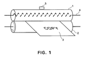
- FIG. 1 shows a general fixing roller.
- the fixing roller comprises a heater roller 1 containing a heater 4 therein, and a pressing roller 2 urged to the heater roller 1.
- a sheet 3 between the rollers 1, 2 By passing a sheet 3 between the rollers 1, 2, the toner image is fused on the sheet 3.
- a thermister 5 temperature sensor
- Figure 2 show a heater electric power supply current waveform in a conventional ON/OFF control for temperature adjustment of the heater roller 1.
- portions P1 and P2 indicate portions of abrupt current change corresponding to points of switching between OFF state and ON state.
- the current variation produces a voltage variation of the supply AC voltage source itself, with the result of flickering of illumination or the like which is energized by the same voltage source.
- there is, in general, a relatively small voltage source impedance Rs as the voltage is seen from the outside an electrical outlet of the voltage source. Therefore, when the consumption current of the connection equipment (copying machine) D to the voltage source AC significantly and abruptly changes, the power source voltage changes due to the voltage drop through the voltage source impedance Rs.
- the abrupt change of the current is ⁇ I
- the abrupt power source voltage variation causes flickering of the illumination, It is desired to reduce the power source voltage variation due to abrupt current change.
- the abrupt current change portion at the ON or OFF portion P1, P2 of the halogen heater power supplying current is required to be mitigated.
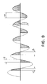
- one of the conventional methods to accomplish this is to control the electric power supply to the heater using a phase control (conduction angle control) as shown in Figure 3.
- the applied voltage is gradually, in effect, increased.
- the electric power supply time in each of he half wave of t AC power source voltage is first set at a small level, and it is gradually increased (t1, t2, t3...tn), in accordance with a heater electric power supply current waveform as shown in Figure 3.
- Japanese Patent Application No.2000 237162 discloses a wave number control proposed by the inventors of the subject application.
- a skipping control is effected with unit three waves, with which the electric power supplying current can be selectable from four stepwise levels.
- this method it is possible to reduce the harmonic current and/or the contact noise appearing in the voltage source line.
- the flickering could be reduced to a certain extent.
- the change in the current changes with increment of 1/3 of full power supply, and therefore, it is effective from the standpoint of reduction of the flickering value.
- this is not sufficient.
- the usable electric power supply levels are four, and in order to increase the number of levels, it is necessary to increase the number of waves.
- a fixing device comprising a fixing heater for being supplied with an AC voltage to generate heat; control means for variably controlling power of supplied electric energy to the fixing heater, wherein one cyclic period for changing the electric power comprises a plurality of waves, and the one cyclic period including a portion in which an electric power supply phase is changed and a portion in which a number of waves of the electric power supply is controlled.
- Figure 1 is a substantial view of a fixing device.
- Figure 2 shows a heater electric power supply current waveform in a conventional ON/OFF control operation for temperature adjustment of the heater roller shown in Figure 1.
- Figure 3 illustrates electric power supply to the heater in a conventional phase control (conduction angle control).
- Figure 4 illustrates a relatively small voltage source impedance Rs as the power source is seen from outside of the voltage source electrical outlet.
- Figure 5 shows all of the electric power supply patterns in this embodiment.
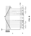
- Figure 6 illustrates a proportional control at seven different levels in this embodiment.
- Figure 7 is a circuit diagram of a system implementing the seven level proportional controlling operation shown in Figure 6.
- Figure 8 is a flow chart of process steps of the interruption routine by a CPU shown in Figure 7.
- FIG. 9 illustrates another embodiment of the present invention.
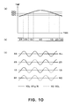
- Figure 10 illustrates a basic operation of a multi-level proportional control.
- a basic unit for which the power of supplied electric energy is variable is constituted by continuous 3 half waves and which forms one period.
- the half waves only one half wave is subjected to a phase control, and the two half waves are subjected to a wave number control (full power supply or no power supply to each of the half waves).
- Figure 5 shows all of the electric power supply patterns.
- an indicates a non-electric power supply pattern.
- Indicated by b is a pattern (p/3) in which only the phase control half waves in the unit three half waves (one cyclic period of control).
- Indicated by c is a pattern in which the power is full supplied in half waves (1/3).
- d is a pattern in which the half wave full power and the phase control half wave supply ((1+p) /3); e is a pattern in which the full power is supplied for two half waves out of three half waves (2/3); f is a pattern in which the full power is supplied for two half waves out of three half waves and the rest is phase-controlled ((2+P)/3); g is a pattern of full power supply. Using the seven electric power supply patterns a-g, a continuous electric power control is accomplished.
- the phase control portion comes once in three half waves, an amount of contact noise appearing in the high investigation wave current and voltage source line is reduced. Therefore, the capacities of a choke coil and a voltage source line filter which are provided in series with the heater, can be reduced.
- Vrp/3 (1/ 3 )(Vm/ 2 ) ( 1-2t1/T+(1/2 ⁇ )sin4 ⁇ t1/T)
- Vrms is an effective value of the total electric power supply pattern g
- Vm is a peak voltage
- Vr (1+p)/3 (1/ 3 ) (Vm/ 2 ) ( 2-2t1/T+(1/2 ⁇ )sin4 ⁇ t1/T)
- Vr (2+p)/3 (1/ 3 )(Vm/ 2 ) ( 3-2t1/T+(1/2 ⁇ )sin4 ⁇ t1/T)
- seven voltage levels (electric power supply patterns a) can be produced including zero voltage.
- t four-value control can be expanded to seven-value proportional control, despite the fact that three half wave periods are equally used.
- the roller detected temperature level is divided by six thresholds TMPa, TMPb, TMPc, TMPd, TMPe and TMPf (TMPa>TMPb>TMPc>TMPd>TMPe> TMPf).
- TMPa, TMPb, TMPc, TMPd, TMPe and TMPf TMPa>TMPb>TMPc>TMPd>TMPe> TMPf.
- the heater when the temperature is TMP ⁇ TMPa, the heater is supplied with the voltage having the electric power supply pattern a (no electric power supply (0/3).
- TMPa ⁇ TMP>TMPb the heater is supplied with the electric power supply pattern b (p/3).
- TMPb ⁇ TMP>TMPc the electric power of the supply pattern c (1/3) is supplied.
- TMPc ⁇ TMP>TMPd the electric power supply pattern d of (1+p)/3 is used.
- the electric power supply pattern e of (2/3) is used.
- TMPe ⁇ TMP> TMPf electric power supply pattern f (2+p)) /3 is used.
- t temperature becomes lower than or equal to TMPf the heater is supplied with full power using the electric power supply pattern g of (3/3).
- the electric power supply pattern changes in the order of a, b, c, d, e, f and g in accordance with the temperature change.
- the electric power supply pattern changes in the opposite direction, too.
- the change of the temperature of the fixing roller is normally much gradual as compared with the current change relating to flickering, and therefore, the stepwise current change of the effective voltage applied by the electric power supply patterns corresponding to the temperature change is gradual. This is considered sufficiently effective to reduction the flickering value.
- FIG 7 is a circuit diagram for accomplishing the proportional controlling operation using seven levels in this embodiment.
- Designated by TH in the Figure is a thermister (5 in Figure 1) for detecting a temperature of a heater roller (1 in Figure 1).
- the thermister 5 is connected with a resistance R1, and a partial potential is inputted to an analog input contact A/D of a CPU.
- the signal supplied to the A/D contact is subjected to an analog/digital conversion and then processed in the CPU.
- the INT input contact of the CPU is supplied with a zero-cross pulse in relation to the power source voltage.
- the zero-cross pulse is generated by a comparator COM and a photo-coupler PC which receives an AC voltage inputted thereto from the power source voltage input ends a, b through resistance R5.
- the zero-cross pulse generation circuit per se is known.
- an interruption routine (which will be described hereinafter) in the CPU is started.
- an internal delay timer TIM is rest.
- the output T0 is H level, and a delay timer value t is set and started.
- the timer output T0 of the delay timer TIM becomes Low when time t elapses after the start.
- the timer output of the L level functions to generate a heater turn on signal to control the heater HT.
- a transistor TR when the T0 output is at the H level, a transistor TR is rendered OFF, so that emission side of a photo-TRIAC PT is OFF. A receipt side of the photo-TRIAC PT is also OFF, no gate current flows in t TRIAC T. Therefore, the TRIAC T is in the OFF, and heater HT is not energized.
- the timer output T0 when the timer output T0 is at the LOW level, the operation is opposite to the above-described. More particularly, the transistor TR is ON, and the light emitting diode of the photo-TRIAC PT lights on, and the light receiving side of the photo-TRIAC PT is also ON.
- the gate of the TRIAC T is supplied with a gate current limited by a resistance R2 or R3. Therefore, the TRIAC T becomes conductive, and the heater HT is supplied with electric energy.
- a resistance R4 and a capacitor C1 connected in parallel with the TRIAC T constitutes a RC circuit, and it is effective to prevent sponteneous actuation of the TRIAC T when the power source voltage changes abruptly due to an external noise.
- an output delay timer TIM is stopped (reset) (S1).
- the output T0 at this time is at H level, and therefore, the emission side of the photo-TRIAC PT is rendered OFF. Therefore, the photo-TRIAC T is in the OFF state, and the heater is light OFF.
- a skipping counter is incremented (+1) (S2).
- the thinning or skipping counter is incremented for each interrupting operation (INT), but is reset to zero when it reaches 2. Namely, the count changes 0, 1, 2,0, 1.... By monitoring the counts, the one of the three consecutive half waves which is the current object of control can be known.
- step S3 the discrimination is made as to whether the count of the counter added immediately before, has reached 3 or not. If so, it is reset to the initial level 0, and if not, the operation goes to step S7.
- the counter is reset to 0, that is, at a rate of once three interruptions, the partial potential of the roller temperature thermister TH is taken after A/D conversion (S5).
- temperature level data is set correspondingly to the taken temperature value. This corresponds to the temperature threshold shown in Figure 6.
- TMP> TMPa the temperature level data is set to 0.
- TMPa ⁇ TMP>TMPb it is set to 1. Similar discriminations and settings are carried out, and finally, if TMP ⁇ TMPf, 6 is set.
- TMP ⁇ TMPf 6 is set.
- TMP ⁇ TMPf 6 is set.
- the discrimination is made as to whether or not the temperature level data is 0, that is, whether or not the roller temperature exceeds TMPa. If it exceeds TMPa, the operation goes to No side, and then nothing is done (the heater is kept unengergized), and the operation returns. If it is not more than TMPa, the operation proceeds to a discrimination step S8.
- the discrimination is first made as to whether or not the skipping counter is 0 (S9). If so, a proper timer value T/4 (the time required for the phase angle of 90° to be reached) (S22), and the timer TIM is started (S23). The timer TIM switches the output T0 to the L level from the H level T/4 after the start. In this manner, the heater energizing time control of phase 90° is carried out when the count of the skipping counter is 0.
- step S8 The operation returns to step S8, and if the TMPLVL data indicate 2, the operation goes to No side, and in the subsequent discrimination step S10, it goes to Yes side. If the skipping counter is 0 in the subsequent discrimination step S11, the operation goes to Yes side, and 0 is set in the delay timer TIM (S24). Then, as soon as the timer starts (S25), the output T0 switches from the H level to the L level, so that heater is actuated.
- the heater is actuated the seven level (value) proportional control responsive to the temperature range shown in Figure 6, according to this embodiment. These operation are controlled by software.
- the electric power supply pattern which is a combination of the wave number control and the phase control shown for example in Figure 5 may be used for the ON/OFF control (bi-level control) of the heater.
- TMPs temperature threshold
- the electric power supply pattern an of non- electric power supply 0/3 is selected for the heater.
- the heater in a conventional bi-level control system, is supplied with the full-power.
- the current is gradually increased using seven electric power supply patterns shown in Figure 5, which is a combination of a wave number control and a phase control for a predetermined period Sn immediately after start of actuation.
- the current is gradually decreased to the state of electric power supply 0/3, using the seven electric power supply patterns shown in Figure 5 for a predetermined period S0 immediately after that.
- the phase control and the wave number control are combined in a segmentalized manner so that current can be more finely set in a cyclic period.
- the flickering can be further decreased, and generations of the harmonic current and noise at the power source line contact can be further reduced.
- the number of unit waves may be four or larger. By doing so, the flickering can be further reduced. As compared with a general phase control, the generations of the harmonic current and the noise at the power source line contact can be reduced.
- a fixing device includes a fixing heater for being supplied with an AC voltage to generate heat; control means for variably controlling power of supplied electric energy to the fixing heater, wherein one cyclic period for changing the electric power comprises a plurality of waves, and the one cyclic period including a portion in which an electric power supply phase is changed and a portion in which a number of waves of the electric power supply is controlled.
Landscapes
- Physics & Mathematics (AREA)
- General Physics & Mathematics (AREA)
- Engineering & Computer Science (AREA)
- Microelectronics & Electronic Packaging (AREA)
- Control Of Resistance Heating (AREA)
- Fixing For Electrophotography (AREA)
- Control Of Temperature (AREA)
- Control Of Electrical Variables (AREA)
Abstract
Description
- The present invention relates to a fixing device for use with an image forming apparatus such as a copying machine, printer or the like using an electrophotographic type or electrostatic recording type process. An addition heat fixing type is widely used for a fixing device in the image forming apparatus, and the heater of the heat-fixing device uses a halogen lamp which requires a relatively consumption current. Upon actuation thereof, a large current suchh as an inrush current flows, with the result of large current variation.
- Figure 1 shows a general fixing roller. The fixing roller comprises a
heater roller 1 containing aheater 4 therein, and apressing roller 2 urged to theheater roller 1. By passing asheet 3 between therollers sheet 3. In order to detect the temperature of theheater roller 1, there is provided a thermister 5 (temperature sensor). - Figure 2 show a heater electric power supply current waveform in a conventional ON/OFF control for temperature adjustment of the
heater roller 1. In the waveform, portions P1 and P2 indicate portions of abrupt current change corresponding to points of switching between OFF state and ON state. The current variation produces a voltage variation of the supply AC voltage source itself, with the result of flickering of illumination or the like which is energized by the same voltage source. More particularly, as shown in Figure 4, there is, in general, a relatively small voltage source impedance Rs, as the voltage is seen from the outside an electrical outlet of the voltage source. Therefore, when the consumption current of the connection equipment (copying machine) D to the voltage source AC significantly and abruptly changes, the power source voltage changes due to the voltage drop through the voltage source impedance Rs. When the abrupt change of the current is δI, the abrupt variation minute δ V of the power source voltage is as follows: - For example, if an illumination device L is connected with the electrical outlet line, the abrupt power source voltage variation causes flickering of the illumination, It is desired to reduce the power source voltage variation due to abrupt current change.
- In order to reduce the abrupt current change (reduction of the flickering value) due to t halogen heater used with the fixing device in a copying machine or the like, the abrupt current change portion at the ON or OFF portion P1, P2 of the halogen heater power supplying current is required to be mitigated.
one of the conventional methods to accomplish this is to control the electric power supply to the heater using a phase control (conduction angle control) as shown in Figure 3. As described in the foregoing, in order to prevention an abrupt current change as in the case of the generation of the abutment entering current immediately after actuation of the heater, the applied voltage is gradually, in effect, increased. For example, the electric power supply time in each of he half wave of t AC power source voltage is first set at a small level, and it is gradually increased (t1, t2, t3...tn), in accordance with a heater electric power supply current waveform as shown in Figure 3. - It is possible to provide a gradual current change. However, the conduction of the heater begins not at the zero-cross starting point but in the middle of the half wave, therefore the harmonic current and the contact noise in the voltage source line is not avoidable.
- As a method for solving the problem, Japanese Patent Application No.2000 237162 discloses a wave number control proposed by the inventors of the subject application. In this method, a skipping control is effected with unit three waves, with which the electric power supplying current can be selectable from four stepwise levels. With this method, it is possible to reduce the harmonic current and/or the contact noise appearing in the voltage source line. In addition, the flickering could be reduced to a certain extent.
- Figure 10 shows this method.
- As shown in the Figure, (a), four boundary temperature values TMPa, TMPb, TMPc (TMPa>TMPb> TMPc) at which the electric power supply pattern is switched in each of the unit cyclic period, and the electric power supply patterns are assigned to the rep temperature ranges as shown in the Figure at (c). As shown in the Figure, (a), when the temperature changes sequentially in the increasing order, namely, TMPc, TMPb, TMPa, and then changes in the decreasing order, namely, TMPa, TMPb, TMPc, the electric power supply pattern changes in the order of 3/3, 2/3, 1/3,0/3, 1/3, 2/3, 3/3. The temperature of the fixing roller relatively gradually changes, and therefore, the voltage applied to the heater has stepwisely different electric power supply pattern.
- With this method, the change in the current changes with increment of 1/3 of full power supply, and therefore, it is effective from the standpoint of reduction of the flickering value. However, this is not sufficient. However, the usable electric power supply levels are four, and in order to increase the number of levels, it is necessary to increase the number of waves.
- Accordingly, it is a principal object of the present invention to provide a fixing device wherein the flickering can be reduced. It is another object of the present invention to provide a fixing device wherein the electric power supply level can be changed to a great number of levels with a small number of waves. According to an aspect of the present invention, there is provided a fixing device comprising a fixing heater for being supplied with an AC voltage to generate heat; control means for variably controlling power of supplied electric energy to the fixing heater, wherein one cyclic period for changing the electric power comprises a plurality of waves, and the one cyclic period including a portion in which an electric power supply phase is changed and a portion in which a number of waves of the electric power supply is controlled.
- These and other objects, features and advantages of the present invention will become more apparent upon a consideration of the following description of the preferred embodiments of the present invention taken in conjunction with the accompanying drawings.
- Figure 1 is a substantial view of a fixing device.
- Figure 2 shows a heater electric power supply current waveform in a conventional ON/OFF control operation for temperature adjustment of the heater roller shown in Figure 1.
- Figure 3 illustrates electric power supply to the heater in a conventional phase control (conduction angle control).
- Figure 4 illustrates a relatively small voltage source impedance Rs as the power source is seen from outside of the voltage source electrical outlet.
- Figure 5 shows all of the electric power supply patterns in this embodiment.
- Figure 6 illustrates a proportional control at seven different levels in this embodiment.
- Figure 7 is a circuit diagram of a system implementing the seven level proportional controlling operation shown in Figure 6.
- Figure 8 is a flow chart of process steps of the interruption routine by a CPU shown in Figure 7.
- Figure 9 illustrates another embodiment of the present invention.
- Figure 10 illustrates a basic operation of a multi-level proportional control.
- The preferred embodiments of the present invention will be described in conjunction with the accompanying drawings.
- The structure shown in Figure 1 is used in this embodiment.
- In this embodiment, a basic unit for which the power of supplied electric energy is variable is constituted by continuous 3 half waves and which forms one period. Among the half waves, only one half wave is subjected to a phase control, and the two half waves are subjected to a wave number control (full power supply or no power supply to each of the half waves). Figure 5 shows all of the electric power supply patterns. In Figure 5, an indicates a non-electric power supply pattern. Indicated by b is a pattern (p/3) in which only the phase control half waves in the unit three half waves (one cyclic period of control). Indicated by c is a pattern in which the power is full supplied in half waves (1/3). Similarly, d is a pattern in which the half wave full power and the phase control half wave supply ((1+p) /3); e is a pattern in which the full power is supplied for two half waves out of three half waves (2/3); f is a pattern in which the full power is supplied for two half waves out of three half waves and the rest is phase-controlled ((2+P)/3); g is a pattern of full power supply. Using the seven electric power supply patterns a-g, a continuous electric power control is accomplished.
- With such an electric power supply pattern, the phase control portion comes once in three half waves, an amount of contact noise appearing in the high investigation wave current and voltage source line is reduced. Therefore, the capacities of a choke coil and a voltage source line filter which are provided in series with the heater, can be reduced.
- For this reason, it is advantages in terms of flickering over a multi-value proportional control disclosed in Japanese Patent Application No.2000237162. This point will be described.
- Effective value voltages of each of the electric power supply patterns shown in Figure 5 will be taken. The electric power supply patterns b, d, f including partial half waves will be considered.
- The effective value voltage Vrp/3 of the three half wave phase control p/3 shown in the electric power supply pattern b is expressed as follows:
- In this equation, when 0 ≤ t1< T/2, 0 ≤ Vrp/3< (1/
- In (1+p)/3 waveform of electric power supply pattern d, the effective value vr(1+p)/3 is:
- When 0 ≤ t1< T/2, it is (1/ v3) Vrms ≤ Vr(1+p)/3<
- In (2+p)/3 waveform of electric power supply pattern d, the effective value Vr(2+p)/3 is:
- When 0 ≤ t1< T/2, it is (1/
- By making selection from the seven electric power supply patterns a-g shown in Figure 5, and t1 is changed in the region of 0 T/2, zero to full levels voltage can be generated.
- For example, in t electric power supply patterns b, d, f in Figure 5, when the phase angle of the partial wave is 90° (the corresponding time t= (cyclic period T) /4), the effective value (effective voltage) is as follows:
- a: (0) effective value= 0
- b: (p/3) effective value = (√(1/6)) Vrms
- c: (1/3) effective value = (√(2/6)) Vrms
- d: (1+p) /3 effective value = (√(3/6)) Vrms
- e: (2/3) effective value = (√(4/6)) Vrms
- f: (2+p) /3 effective value = (√(5/6)) Vrms
- g: (3/3) effective value= Vrms
-
- Thus, seven voltage levels (electric power supply patterns a) can be produced including zero voltage. Here, p/3 is based on a phase angle of 90° (t=AC cyclic period T/4).
- In this embodiment, by using such electric power supply patterns, t four-value control can be expanded to seven-value proportional control, despite the fact that three half wave periods are equally used. Referring to Figure 6, the description will be made as to application of the control. As shown in Figure 6, (a), the roller detected temperature level is divided by six thresholds TMPa, TMPb, TMPc, TMPd, TMPe and TMPf (TMPa>TMPb>TMPc>TMPd>TMPe> TMPf). For the resultant seven temperature levels, the electric power supply patterns a, b, c, d, e, f and g are assigned, as shown in Figure 6, (b), that is, higher temperatures are assigned with lower voltage levels. More particularly, when the temperature is TMP ≥ TMPa, the heater is supplied with the voltage having the electric power supply pattern a (no electric power supply (0/3). When TMPa ≥ TMP>TMPb, the heater is supplied with the electric power supply pattern b (p/3). When TMPb ≥ TMP>TMPc, the electric power of the supply pattern c (1/3) is supplied. When TMPc ≥ TMP>TMPd, the electric power supply pattern d of (1+p)/3 is used. When the temperature level satisfies TMPd ≥ TMP> TMPe, the electric power supply pattern e of (2/3) is used. and when TMPe ≥ TMP> TMPf, electric power supply pattern f (2+p)) /3 is used. When t temperature becomes lower than or equal to TMPf, the heater is supplied with full power using the electric power supply pattern g of (3/3).
- In the case that temperature changes from a point P1 in the highest temperature region to a point P2 in the lowest temperature region, the electric power supply pattern changes in the order of a, b, c, d, e, f and g in accordance with the temperature change. When the temperature changes in the opposite direction, the electric power supply pattern changes in the opposite direction, too.
- The change of the temperature of the fixing roller is normally much gradual as compared with the current change relating to flickering, and therefore, the stepwise current change of the effective voltage applied by the electric power supply patterns corresponding to the temperature change is gradual. This is considered sufficiently effective to reduction the flickering value.
- Figure 7 is a circuit diagram for accomplishing the proportional controlling operation using seven levels in this embodiment. Designated by TH in the Figure is a thermister (5 in Figure 1) for detecting a temperature of a heater roller (1 in Figure 1). The
thermister 5 is connected with a resistance R1, and a partial potential is inputted to an analog input contact A/D of a CPU. The signal supplied to the A/D contact is subjected to an analog/digital conversion and then processed in the CPU. The INT input contact of the CPU is supplied with a zero-cross pulse in relation to the power source voltage. The zero-cross pulse is generated by a comparator COM and a photo-coupler PC which receives an AC voltage inputted thereto from the power source voltage input ends a, b through resistance R5. The zero-cross pulse generation circuit per se is known. In response to a falling of the zero-cross pulse input signal, an interruption routine (which will be described hereinafter) in the CPU is started. Immediately after the falling of the zero-cross signal, an internal delay timer TIM is rest. The output T0 is H level, and a delay timer value t is set and started. The timer output T0 of the delay timer TIM becomes Low when time t elapses after the start. The timer output of the L level functions to generate a heater turn on signal to control the heater HT. - More particularly, when the T0 output is at the H level, a transistor TR is rendered OFF, so that emission side of a photo-TRIAC PT is OFF. A receipt side of the photo-TRIAC PT is also OFF, no gate current flows in t TRIAC T. Therefore, the TRIAC T is in the OFF, and heater HT is not energized. On the contrary, when the timer output T0 is at the LOW level, the operation is opposite to the above-described. More particularly, the transistor TR is ON, and the light emitting diode of the photo-TRIAC PT lights on, and the light receiving side of the photo-TRIAC PT is also ON. Since the light receiving side of the photo-TRIAC PT becomes conductive, the gate of the TRIAC T is supplied with a gate current limited by a resistance R2 or R3. Therefore, the TRIAC T becomes conductive, and the heater HT is supplied with electric energy. A resistance R4 and a capacitor C1 connected in parallel with the TRIAC T constitutes a RC circuit, and it is effective to prevent sponteneous actuation of the TRIAC T when the power source voltage changes abruptly due to an external noise.
- Referring to Figure 8 (flow chart), the description will be made as to the process steps of the interruption routine of the CPU in the circuit shown in Figure 7.
- To the interruption input contact INT to the CPU (Figure 7), a zero-cross pulse in the form of an AC power source voltage, and therefore, for each of the generations of the pulses (here, pulse fallings), the processing in the CPU is interrupted, and the flow process shown in Figure 8 is carried out.
- At the start of the interruption process, an output delay timer TIM is stopped (reset) (S1). The output T0 at this time is at H level, and therefore, the emission side of the photo-TRIAC PT is rendered OFF. Therefore, the photo-TRIAC T is in the OFF state, and the heater is light OFF.
- Then, a skipping counter is incremented (+1) (S2). The thinning or skipping counter is incremented for each interrupting operation (INT), but is reset to zero when it reaches 2. Namely, the count changes 0, 1, 2,0, 1.... By monitoring the counts, the one of the three consecutive half waves which is the current object of control can be known.
- In the next discrimination step S3, the discrimination is made as to whether the count of the counter added immediately before, has reached 3 or not. If so, it is reset to the
initial level 0, and if not, the operation goes to step S7. Each time the counter is reset to 0, that is, at a rate of once three interruptions, the partial potential of the roller temperature thermister TH is taken after A/D conversion (S5). In the next process, temperature level data is set correspondingly to the taken temperature value. This corresponds to the temperature threshold shown in Figure 6. Here, if the temperature satisfies TMP> TMPa, the temperature level data is set to 0. - If TMPa ≥ TMP>TMPb, it is set to 1. Similar discriminations and settings are carried out, and finally, if TMP ≤ TMPf, 6 is set. Thus, one of temperature level (TMPLVL)
data 0 6 is set in accordance with the detected temperature value (temperature region) in this process. - At the next discrimination step S7, the discrimination is made as to whether or not the temperature level data is 0, that is, whether or not the roller temperature exceeds TMPa. If it exceeds TMPa, the operation goes to No side, and then nothing is done (the heater is kept unengergized), and the operation returns. If it is not more than TMPa, the operation proceeds to a discrimination step S8.
- At discrimination step S8, if the TMPLVL data is 1 (TMPa ≥ TMP> TMPb), the discrimination is first made as to whether or not the skipping counter is 0 (S9). If so, a proper timer value T/4 (the time required for the phase angle of 90° to be reached) (S22), and the timer TIM is started (S23). The timer TIM switches the output T0 to the L level from the H level T/4 after the start. In this manner, the heater energizing time control of phase 90° is carried out when the count of the skipping counter is 0.
- When the count of the skipping counter is not 0 at said discrimination step S9, nothing is done, and the operation returns. As a result, the timer output T0 remains unchanged (keeps H level), and therefore, the heater is in the OFF state. Therefore, in the first one of the half waves in which the counts of the skipping counters are 0, the heater is energized with 90° phase, and in the subsequent periods in which the counts of the skipping counter are 1 or 2, the heater is not energized. This corresponds to the electric power supply pattern b in Figure 5.
- The operation returns to step S8, and if the TMPLVL data indicate 2, the operation goes to No side, and in the subsequent discrimination step S10, it goes to Yes side. If the skipping counter is 0 in the subsequent discrimination step S11, the operation goes to Yes side, and 0 is set in the delay timer TIM (S24). Then, as soon as the timer starts (S25), the output T0 switches from the H level to the L level, so that heater is actuated.
- If the result of discrimination at said discrimination step S11 is negative, that is, the count is 1 or 2, nothing is done, and the operation returns. Therefore, the heater remains unactuated. In this manner, the electric power is supplied in the first half wave, and not supplied in the subsequent half waves. This corresponds to the electric power supply pattern c shown in Figure 5.
- When TMPLVL data indicate 3, similar processes are executed at discrimination steps S12, S13, S14, so that heater is controlled with the electric power supply pattern d.
- When TMPLVL data indicate 4, similar processes are executed at discrimination steps S15, S16, S17, so that heater is controlled with the electric power supply patter e.
- When TMPLVL data indicate 5, similar processes are executed at discrimination steps S18, S19, S20, S21, so that heater is controlled with the electric power supply patter f.
- When TMPLVL data indicate 6, the operation branches out to the No side in the discrimination step S18, so that steps S24, S25 are executed irrespective of the count of counter. As a result, the electric power supply pattern g can be accomplished.
- By repeating the above-described operations, the heater is actuated the seven level (value) proportional control responsive to the temperature range shown in Figure 6, according to this embodiment. These operation are controlled by software.
- Referring to Figure 9, another embodiment of the present invention will be described. In the foregoing embodiment, multi-value proportional is used. In this embodiment, the electric power supply pattern which is a combination of the wave number control and the phase control shown for example in Figure 5 may be used for the ON/OFF control (bi-level control) of the heater. In this case, when the roller temperature is higher than a target temperature TMPs (temperature threshold), the electric power supply pattern an of non-
electric power supply 0/3 is selected for the heater. When the temperature is lower than TMPs, the heater, in a conventional bi-level control system, is supplied with the full-power. However, in this embodiment, the current is gradually increased using seven electric power supply patterns shown in Figure 5, which is a combination of a wave number control and a phase control for a predetermined period Sn immediately after start of actuation. When t roller temperature becomes higher than a target temperature TMPs, the current is gradually decreased to the state ofelectric power supply 0/3, using the seven electric power supply patterns shown in Figure 5 for a predetermined period S0 immediately after that. - According to the present invention, the phase control and the wave number control are combined in a segmentalized manner so that current can be more finely set in a cyclic period. By doing so, the flickering can be further decreased, and generations of the harmonic current and noise at the power source line contact can be further reduced.
- In the foregoing, the description has been made as to the preferred embodiments of the present invention. The number of unit waves may be four or larger. By doing so, the flickering can be further reduced. As compared with a general phase control, the generations of the harmonic current and the noise at the power source line contact can be reduced.
- While the invention has been described with reference to the structures disclosed herein, it is not confined to the details set forth and this application is intended to cover such modifications or changes as may come within the purpose of the improvements or the scope of the following claims.
- A fixing device includes a fixing heater for being supplied with an AC voltage to generate heat; control means for variably controlling power of supplied electric energy to the fixing heater, wherein one cyclic period for changing the electric power comprises a plurality of waves, and the one cyclic period including a portion in which an electric power supply phase is changed and a portion in which a number of waves of the electric power supply is controlled.
Claims (4)
- A fixing device comprising:wherein one cyclic period for changing the electric power comprises a plurality of waves, and the one cyclic period including a portion in which an electric power supply phase is changed and a portion in which a number of waves of the electric power supply is controlled.a fixing heater for being supplied with an AC voltage to generate heat;control means for variably controlling power of supplied electric energy to the fixing heater,
- A device according to Claim 1, further comprising a fixing member for applying heat from the fixing heater to an unfixed image, and a temperature detecting member for detecting a temperature of said fixing member, wherein said control means temperatures the power of supplied electric energy on the basis of an output of said temperature detecting member.
- A device according to Claim 1, wherein the portion for changing the electric power supply phase is constituted by one wave.
- A device according to Claim 3, wherein the portion for changing the electric power supply phase is constituted by two waves.
Applications Claiming Priority (2)
| Application Number | Priority Date | Filing Date | Title |
|---|---|---|---|
| JP2001314510A JP2003123941A (en) | 2001-10-11 | 2001-10-11 | Heater control method and image forming apparatus |
| JP2001314510 | 2001-10-11 |
Publications (3)
| Publication Number | Publication Date |
|---|---|
| EP1302817A2 true EP1302817A2 (en) | 2003-04-16 |
| EP1302817A3 EP1302817A3 (en) | 2006-11-15 |
| EP1302817B1 EP1302817B1 (en) | 2013-06-05 |
Family
ID=19132813
Family Applications (1)
| Application Number | Title | Priority Date | Filing Date |
|---|---|---|---|
| EP02022697.3A Expired - Lifetime EP1302817B1 (en) | 2001-10-11 | 2002-10-10 | Fixing device |
Country Status (5)
| Country | Link |
|---|---|
| US (1) | US6853818B2 (en) |
| EP (1) | EP1302817B1 (en) |
| JP (1) | JP2003123941A (en) |
| KR (1) | KR100503843B1 (en) |
| CN (1) | CN100485547C (en) |
Cited By (6)
| Publication number | Priority date | Publication date | Assignee | Title |
|---|---|---|---|---|
| EP1882992A1 (en) * | 2006-06-29 | 2008-01-30 | Samsung Electronics Co., Ltd. | Method and apparatus for controlling fusing temperature, and image forming apparatus |
| EP1698948A4 (en) * | 2003-12-26 | 2010-04-07 | Canon Finetech Inc | Fixation heater control method and image formation device |
| EP2261754A1 (en) * | 2009-06-08 | 2010-12-15 | Canon Kabushiki Kaisha | Image forming apparatus |
| US8213822B2 (en) * | 2008-12-30 | 2012-07-03 | Lexmark International, Inc. | Power control for a printer fuser |
| WO2018010785A1 (en) * | 2016-07-13 | 2018-01-18 | Hewlett-Packard Development Company, L.P. | Ac power control |
| EP2261755B1 (en) * | 2009-06-11 | 2019-08-07 | Canon Kabushiki Kaisha | Image forming apparatus |
Families Citing this family (40)
| Publication number | Priority date | Publication date | Assignee | Title |
|---|---|---|---|---|
| JP2004303469A (en) * | 2003-03-28 | 2004-10-28 | Brother Ind Ltd | Heating device and image forming device |
| JP2007163603A (en) * | 2005-12-09 | 2007-06-28 | Harison Toshiba Lighting Corp | Fixing device driving device |
| KR100739796B1 (en) * | 2006-02-16 | 2007-07-13 | 삼성전자주식회사 | Power control method and apparatus for heating roller |
| KR100846785B1 (en) * | 2006-03-14 | 2008-07-16 | 삼성전자주식회사 | Power control method and apparatus for heating roller and phase control circuit for same |
| KR101309785B1 (en) * | 2006-07-28 | 2013-09-23 | 삼성전자주식회사 | Phase controlling device and fuser controlling device having the same and method of the phase controlling |
| KR20080072531A (en) * | 2007-02-01 | 2008-08-06 | 삼성전자주식회사 | Fuser and image forming apparatus and control method thereof |
| US7912397B2 (en) * | 2007-02-01 | 2011-03-22 | Samsung Electronics Co., Ltd. | Fuser, image forming apparatus, and method to control the apparatus |
| JP5110904B2 (en) * | 2007-02-26 | 2012-12-26 | キヤノン株式会社 | Power control apparatus and image forming apparatus |
| JP5305982B2 (en) | 2008-03-07 | 2013-10-02 | キヤノン株式会社 | Energization control device and image forming apparatus |
| JP2009237070A (en) | 2008-03-26 | 2009-10-15 | Brother Ind Ltd | Heater controller and image forming apparatus |
| EP2146546A1 (en) * | 2008-07-17 | 2010-01-20 | Microlife Intellectual Property GmbH | Heater wire control circuit and method to operate a heating element |
| KR101273509B1 (en) * | 2008-08-01 | 2013-06-17 | 삼성전자주식회사 | Image forming apparatus and control mehtod of fuser of the same |
| JP2010237283A (en) | 2009-03-30 | 2010-10-21 | Canon Inc | Image forming apparatus |
| JP5847874B2 (en) * | 2009-06-08 | 2016-01-27 | キヤノン株式会社 | Image forming apparatus |
| JP5550263B2 (en) * | 2009-06-11 | 2014-07-16 | キヤノン株式会社 | Image forming apparatus |
| JP5350087B2 (en) * | 2009-06-11 | 2013-11-27 | キヤノン株式会社 | Image forming apparatus |
| US8530800B2 (en) * | 2009-09-15 | 2013-09-10 | Ricoh Company, Limited | Heater control device, image forming apparatus, and computer program product |
| KR101082722B1 (en) * | 2009-09-24 | 2011-11-10 | (주)엘지하우시스 | A Heat Control Device of Generating Heat Glass |
| JP5471618B2 (en) * | 2010-03-05 | 2014-04-16 | 株式会社リコー | HEATER CONTROL DEVICE, IMAGE FORMING DEVICE, HEATER CONTROL METHOD, AND PROGRAM |
| JP5465092B2 (en) * | 2010-06-03 | 2014-04-09 | キヤノン株式会社 | Fixing apparatus and image forming apparatus |
| JP5713648B2 (en) * | 2010-11-29 | 2015-05-07 | キヤノン株式会社 | Image forming apparatus |
| JP5744497B2 (en) * | 2010-12-09 | 2015-07-08 | キヤノン株式会社 | Image forming apparatus |
| JP2012123244A (en) | 2010-12-09 | 2012-06-28 | Canon Inc | Image forming apparatus |
| JP5761983B2 (en) * | 2010-12-15 | 2015-08-12 | キヤノン株式会社 | Image forming apparatus |
| JP5424066B2 (en) | 2011-03-08 | 2014-02-26 | ブラザー工業株式会社 | Heating apparatus and image forming apparatus |
| JP5370782B2 (en) | 2011-03-08 | 2013-12-18 | ブラザー工業株式会社 | Image forming apparatus |
| JP6039219B2 (en) * | 2012-04-06 | 2016-12-07 | キヤノン株式会社 | Heating apparatus and image forming apparatus |
| JP6071645B2 (en) * | 2013-02-28 | 2017-02-01 | キヤノン株式会社 | Fixing apparatus, image forming apparatus, and power supply control method |
| JP6572605B2 (en) * | 2014-08-07 | 2019-09-11 | 株式会社リコー | HEATER CONTROL DEVICE, IMAGE FORMING DEVICE, HEATER CONTROL METHOD, AND PROGRAM |
| KR20160028232A (en) | 2014-09-03 | 2016-03-11 | 삼성전자주식회사 | image forming apparatus and phase control method |
| US9639038B1 (en) * | 2015-12-31 | 2017-05-02 | Lexmark International, Inc. | Power management and control for a fuser of an electrophotographic imaging device |
| US10524312B2 (en) | 2016-07-01 | 2019-12-31 | Weber-Stephen Products Llc | Electric grill with current protection circuitry |
| US10537199B2 (en) | 2016-07-01 | 2020-01-21 | Weber-Stephen Products Llc | Digital power supply |
| US10551893B2 (en) | 2016-07-01 | 2020-02-04 | Weber-Stephen Products Llc | Digital power supply with wireless monitoring and control |
| WO2018182735A1 (en) | 2017-03-31 | 2018-10-04 | Hewlett-Packard Development Company, L.P. | Simultaneous use of phase control and integral half cycle (ihc) control |
| CA3000542C (en) * | 2017-05-05 | 2021-11-02 | Weber-Stephen Products Llc | Digital power supply with wireless monitoring and control |
| KR20200014067A (en) * | 2018-07-31 | 2020-02-10 | 휴렛-팩커드 디벨롭먼트 컴퍼니, 엘.피. | Method for controlling fuser |
| JP7621806B2 (en) | 2021-01-25 | 2025-01-27 | キヤノン株式会社 | Image forming device |
| WO2023112233A1 (en) * | 2021-12-15 | 2023-06-22 | 住友電気工業株式会社 | Heater control device and power control method |
| JP2023160288A (en) | 2022-04-22 | 2023-11-02 | キヤノン株式会社 | Image forming device |
Citations (4)
| Publication number | Priority date | Publication date | Assignee | Title |
|---|---|---|---|---|
| DE2419035A1 (en) | 1973-04-19 | 1974-11-07 | Canon Kk | TEMPERATURE CONTROL SYSTEM |
| EP0797130A2 (en) | 1996-03-21 | 1997-09-24 | Canon Kabushiki Kaisha | Image heating apparatus |
| JPH11272103A (en) | 1998-03-26 | 1999-10-08 | Konica Corp | Heater driving device |
| JP2000237162A (en) | 1999-02-22 | 2000-09-05 | Toshiba Corp | MR image continuous reconstruction method and MRI apparatus |
Family Cites Families (19)
| Publication number | Priority date | Publication date | Assignee | Title |
|---|---|---|---|---|
| GB8432542D0 (en) * | 1984-12-21 | 1985-02-06 | Micropore International Ltd | Power control arrangement |
| JPH0320651Y2 (en) * | 1986-06-30 | 1991-05-02 | ||
| JPH05257545A (en) * | 1992-03-16 | 1993-10-08 | Minolta Camera Co Ltd | Heater driving device |
| JP3170857B2 (en) * | 1992-03-27 | 2001-05-28 | キヤノン株式会社 | Heating equipment |
| JP3226967B2 (en) * | 1992-06-29 | 2001-11-12 | キヤノン株式会社 | Fixing device |
| JPH07324756A (en) * | 1994-05-31 | 1995-12-12 | Toshiba Corp | Heater |
| US5669038A (en) * | 1995-04-27 | 1997-09-16 | Konica Corporation | Heater controlling apparatus and a fixing apparatus of an electrophotographic apparatus in use therewith |
| JPH0980961A (en) * | 1995-09-07 | 1997-03-28 | Konica Corp | Fixing device and electrophotographic device |
| JPH09329991A (en) * | 1996-06-10 | 1997-12-22 | Canon Inc | Image forming device |
| JPH1010917A (en) * | 1996-06-20 | 1998-01-16 | Canon Inc | Heat fixing device |
| US6037576A (en) * | 1996-08-30 | 2000-03-14 | Minolta Co., Ltd. | Apparatus and method for detecting a condition in an inductive heating device |
| JPH10177319A (en) * | 1996-12-18 | 1998-06-30 | Canon Inc | Fixing device and image forming device |
| JPH10312133A (en) * | 1997-05-13 | 1998-11-24 | Canon Inc | Heating device and image forming device |
| US6301454B1 (en) | 1997-09-18 | 2001-10-09 | Copyer Co., Ltd. | Fixing heater controlling method and an image forming device |
| JP3316170B2 (en) * | 1997-09-18 | 2002-08-19 | コピア株式会社 | Fixing heater control method and image forming apparatus |
| JP3389475B2 (en) * | 1997-09-19 | 2003-03-24 | シャープ株式会社 | Image forming device |
| JPH11190949A (en) * | 1997-12-25 | 1999-07-13 | Canon Inc | Image heating device and image forming device |
| JP3376279B2 (en) * | 1998-06-03 | 2003-02-10 | キヤノン株式会社 | Fixing device |
| JP2000098796A (en) * | 1998-09-22 | 2000-04-07 | Ricoh Co Ltd | Fixing device |
-
2001
- 2001-10-11 JP JP2001314510A patent/JP2003123941A/en active Pending
-
2002
- 2002-10-10 EP EP02022697.3A patent/EP1302817B1/en not_active Expired - Lifetime
- 2002-10-10 US US10/267,870 patent/US6853818B2/en not_active Expired - Fee Related
- 2002-10-11 KR KR10-2002-0061983A patent/KR100503843B1/en not_active Expired - Fee Related
- 2002-10-11 CN CNB021514879A patent/CN100485547C/en not_active Expired - Fee Related
Patent Citations (4)
| Publication number | Priority date | Publication date | Assignee | Title |
|---|---|---|---|---|
| DE2419035A1 (en) | 1973-04-19 | 1974-11-07 | Canon Kk | TEMPERATURE CONTROL SYSTEM |
| EP0797130A2 (en) | 1996-03-21 | 1997-09-24 | Canon Kabushiki Kaisha | Image heating apparatus |
| JPH11272103A (en) | 1998-03-26 | 1999-10-08 | Konica Corp | Heater driving device |
| JP2000237162A (en) | 1999-02-22 | 2000-09-05 | Toshiba Corp | MR image continuous reconstruction method and MRI apparatus |
Cited By (8)
| Publication number | Priority date | Publication date | Assignee | Title |
|---|---|---|---|---|
| EP1698948A4 (en) * | 2003-12-26 | 2010-04-07 | Canon Finetech Inc | Fixation heater control method and image formation device |
| EP1882992A1 (en) * | 2006-06-29 | 2008-01-30 | Samsung Electronics Co., Ltd. | Method and apparatus for controlling fusing temperature, and image forming apparatus |
| US8213822B2 (en) * | 2008-12-30 | 2012-07-03 | Lexmark International, Inc. | Power control for a printer fuser |
| EP2261754A1 (en) * | 2009-06-08 | 2010-12-15 | Canon Kabushiki Kaisha | Image forming apparatus |
| US8494383B2 (en) | 2009-06-08 | 2013-07-23 | Canon Kabushiki Kaisha | Image forming apparatus controlling power from a commercial AC power supply to a heater and detecting current flowing in a power supply path from the commercial AC power supply to the heater |
| US9170550B2 (en) | 2009-06-08 | 2015-10-27 | Canon Kabushiki Kaisha | Image forming apparatus controlling power from an AC power supply to a heater in accordance with the temperature sensed by a temperature sensing element |
| EP2261755B1 (en) * | 2009-06-11 | 2019-08-07 | Canon Kabushiki Kaisha | Image forming apparatus |
| WO2018010785A1 (en) * | 2016-07-13 | 2018-01-18 | Hewlett-Packard Development Company, L.P. | Ac power control |
Also Published As
| Publication number | Publication date |
|---|---|
| US6853818B2 (en) | 2005-02-08 |
| EP1302817A3 (en) | 2006-11-15 |
| EP1302817B1 (en) | 2013-06-05 |
| JP2003123941A (en) | 2003-04-25 |
| CN100485547C (en) | 2009-05-06 |
| KR20030030962A (en) | 2003-04-18 |
| CN1412626A (en) | 2003-04-23 |
| KR100503843B1 (en) | 2005-07-27 |
| US20030072581A1 (en) | 2003-04-17 |
Similar Documents
| Publication | Publication Date | Title |
|---|---|---|
| EP1302817A2 (en) | Fixing device | |
| EP1679781B1 (en) | Electric power control device for a fixing heater | |
| US8103183B2 (en) | Heater control with varying control cycle and lighting pattern | |
| US7511727B2 (en) | Fixation heater control method and image formation device | |
| WO1999014639A1 (en) | Fixing heater controlling method and an image forming device | |
| EP1462902B1 (en) | Heating unit and image formation apparatus | |
| US6157010A (en) | Heater control device | |
| CN101114153B (en) | Phase controlling device, fuser controlling device having the same, and phase controlling method | |
| JP3316170B2 (en) | Fixing heater control method and image forming apparatus | |
| JP2006073431A (en) | Heating device, fixing device, and control method of heating device | |
| JP2002050450A (en) | Heater control method and image forming apparatus | |
| JP4539453B2 (en) | HEATER CONTROL DEVICE, IMAGE FORMING DEVICE, HEATER CONTROL METHOD, AND PROGRAM | |
| US7965956B2 (en) | Image forming apparatus preventing power supply during initialization and control method thereof | |
| JP6555059B2 (en) | Image forming apparatus, image forming apparatus control method, and computer program | |
| JP2006184418A (en) | Fixing device | |
| JP7073960B2 (en) | Heater control device and image forming device | |
| JP7536570B2 (en) | Image forming device | |
| JPH0916018A (en) | Heater controller | |
| JPS5933480A (en) | Heater driving device of fixation device for copying machine | |
| HK1011763B (en) | Heat fixing apparatus | |
| JP2006145590A (en) | Fixing device | |
| JP2000250639A (en) | Power controller for thermal fixing unit | |
| JP2000172108A (en) | Fixing device/method | |
| JPH06302372A (en) | Temperature control method for heating device |
Legal Events
| Date | Code | Title | Description |
|---|---|---|---|
| PUAI | Public reference made under article 153(3) epc to a published international application that has entered the european phase |
Free format text: ORIGINAL CODE: 0009012 |
|
| 17P | Request for examination filed |
Effective date: 20021010 |
|
| AK | Designated contracting states |
Designated state(s): AT BE BG CH CY CZ DE DK EE ES FI FR GB GR IE IT LI LU MC NL PT SE SK TR |
|
| AX | Request for extension of the european patent |
Extension state: AL LT LV MK RO SI |
|
| PUAL | Search report despatched |
Free format text: ORIGINAL CODE: 0009013 |
|
| AK | Designated contracting states |
Kind code of ref document: A3 Designated state(s): AT BE BG CH CY CZ DE DK EE ES FI FR GB GR IE IT LI LU MC NL PT SE SK TR |
|
| AX | Request for extension of the european patent |
Extension state: AL LT LV MK RO SI |
|
| AKX | Designation fees paid |
Designated state(s): DE FR GB IT |
|
| 17Q | First examination report despatched |
Effective date: 20090525 |
|
| GRAJ | Information related to disapproval of communication of intention to grant by the applicant or resumption of examination proceedings by the epo deleted |
Free format text: ORIGINAL CODE: EPIDOSDIGR1 |
|
| GRAP | Despatch of communication of intention to grant a patent |
Free format text: ORIGINAL CODE: EPIDOSNIGR1 |
|
| GRAP | Despatch of communication of intention to grant a patent |
Free format text: ORIGINAL CODE: EPIDOSNIGR1 |
|
| GRAS | Grant fee paid |
Free format text: ORIGINAL CODE: EPIDOSNIGR3 |
|
| GRAA | (expected) grant |
Free format text: ORIGINAL CODE: 0009210 |
|
| AK | Designated contracting states |
Kind code of ref document: B1 Designated state(s): DE FR GB IT |
|
| REG | Reference to a national code |
Ref country code: GB Ref legal event code: FG4D |
|
| REG | Reference to a national code |
Ref country code: DE Ref legal event code: R096 Ref document number: 60245059 Country of ref document: DE Effective date: 20130801 |
|
| PLBE | No opposition filed within time limit |
Free format text: ORIGINAL CODE: 0009261 |
|
| STAA | Information on the status of an ep patent application or granted ep patent |
Free format text: STATUS: NO OPPOSITION FILED WITHIN TIME LIMIT |
|
| 26N | No opposition filed |
Effective date: 20140306 |
|
| PG25 | Lapsed in a contracting state [announced via postgrant information from national office to epo] |
Ref country code: IT Free format text: LAPSE BECAUSE OF FAILURE TO SUBMIT A TRANSLATION OF THE DESCRIPTION OR TO PAY THE FEE WITHIN THE PRESCRIBED TIME-LIMIT Effective date: 20130605 |
|
| REG | Reference to a national code |
Ref country code: DE Ref legal event code: R097 Ref document number: 60245059 Country of ref document: DE Effective date: 20140306 |
|
| REG | Reference to a national code |
Ref country code: FR Ref legal event code: ST Effective date: 20140630 |
|
| PG25 | Lapsed in a contracting state [announced via postgrant information from national office to epo] |
Ref country code: FR Free format text: LAPSE BECAUSE OF NON-PAYMENT OF DUE FEES Effective date: 20131031 |
|
| PGFP | Annual fee paid to national office [announced via postgrant information from national office to epo] |
Ref country code: DE Payment date: 20141031 Year of fee payment: 13 Ref country code: GB Payment date: 20141021 Year of fee payment: 13 |
|
| REG | Reference to a national code |
Ref country code: DE Ref legal event code: R119 Ref document number: 60245059 Country of ref document: DE |
|
| GBPC | Gb: european patent ceased through non-payment of renewal fee |
Effective date: 20151010 |
|
| PG25 | Lapsed in a contracting state [announced via postgrant information from national office to epo] |
Ref country code: DE Free format text: LAPSE BECAUSE OF NON-PAYMENT OF DUE FEES Effective date: 20160503 Ref country code: GB Free format text: LAPSE BECAUSE OF NON-PAYMENT OF DUE FEES Effective date: 20151010 |