EP1302635A2 - Direct injection gasoline engine - Google Patents
Direct injection gasoline engine Download PDFInfo
- Publication number
- EP1302635A2 EP1302635A2 EP02001127A EP02001127A EP1302635A2 EP 1302635 A2 EP1302635 A2 EP 1302635A2 EP 02001127 A EP02001127 A EP 02001127A EP 02001127 A EP02001127 A EP 02001127A EP 1302635 A2 EP1302635 A2 EP 1302635A2
- Authority
- EP
- European Patent Office
- Prior art keywords
- fuel
- engine
- injector
- direct injection
- ignition plug
- Prior art date
- Legal status (The legal status is an assumption and is not a legal conclusion. Google has not performed a legal analysis and makes no representation as to the accuracy of the status listed.)
- Withdrawn
Links
- 238000002347 injection Methods 0.000 title claims abstract description 129
- 239000007924 injection Substances 0.000 title claims abstract description 129
- 239000003502 gasoline Substances 0.000 title claims description 37
- 239000000446 fuel Substances 0.000 claims abstract description 180
- 239000007921 spray Substances 0.000 claims abstract description 85
- 238000002485 combustion reaction Methods 0.000 claims description 77
- 239000000203 mixture Substances 0.000 claims description 46
- 238000005507 spraying Methods 0.000 claims description 19
- 230000006835 compression Effects 0.000 claims description 12
- 238000007906 compression Methods 0.000 claims description 12
- 238000009826 distribution Methods 0.000 claims description 11
- 238000010304 firing Methods 0.000 claims description 7
- 239000003054 catalyst Substances 0.000 claims description 2
- 239000007788 liquid Substances 0.000 abstract description 13
- 239000003570 air Substances 0.000 description 45
- 238000013517 stratification Methods 0.000 description 13
- 238000010586 diagram Methods 0.000 description 10
- 238000000034 method Methods 0.000 description 9
- 230000035515 penetration Effects 0.000 description 9
- 238000009792 diffusion process Methods 0.000 description 6
- 239000007789 gas Substances 0.000 description 5
- 238000002156 mixing Methods 0.000 description 5
- 230000008016 vaporization Effects 0.000 description 4
- 238000000889 atomisation Methods 0.000 description 3
- 230000004888 barrier function Effects 0.000 description 3
- 230000003197 catalytic effect Effects 0.000 description 3
- 239000008240 homogeneous mixture Substances 0.000 description 3
- 229910052703 rhodium Inorganic materials 0.000 description 3
- 239000010948 rhodium Substances 0.000 description 3
- MHOVAHRLVXNVSD-UHFFFAOYSA-N rhodium atom Chemical compound [Rh] MHOVAHRLVXNVSD-UHFFFAOYSA-N 0.000 description 3
- 238000009834 vaporization Methods 0.000 description 3
- 230000003245 working effect Effects 0.000 description 3
- 239000004215 Carbon black (E152) Substances 0.000 description 2
- 239000012080 ambient air Substances 0.000 description 2
- 239000012141 concentrate Substances 0.000 description 2
- 230000007423 decrease Effects 0.000 description 2
- 229930195733 hydrocarbon Natural products 0.000 description 2
- 150000002430 hydrocarbons Chemical class 0.000 description 2
- 238000005192 partition Methods 0.000 description 2
- 238000010791 quenching Methods 0.000 description 2
- 230000009467 reduction Effects 0.000 description 2
- 239000004071 soot Substances 0.000 description 2
- 238000011144 upstream manufacturing Methods 0.000 description 2
- 230000001133 acceleration Effects 0.000 description 1
- 230000009471 action Effects 0.000 description 1
- 230000004913 activation Effects 0.000 description 1
- QVGXLLKOCUKJST-UHFFFAOYSA-N atomic oxygen Chemical compound [O] QVGXLLKOCUKJST-UHFFFAOYSA-N 0.000 description 1
- 230000015572 biosynthetic process Effects 0.000 description 1
- 230000000903 blocking effect Effects 0.000 description 1
- 230000008859 change Effects 0.000 description 1
- 239000002826 coolant Substances 0.000 description 1
- 238000001816 cooling Methods 0.000 description 1
- 238000005520 cutting process Methods 0.000 description 1
- 230000003111 delayed effect Effects 0.000 description 1
- 230000006866 deterioration Effects 0.000 description 1
- 238000010790 dilution Methods 0.000 description 1
- 239000012895 dilution Substances 0.000 description 1
- 230000000694 effects Effects 0.000 description 1
- 239000002828 fuel tank Substances 0.000 description 1
- 229910052736 halogen Inorganic materials 0.000 description 1
- 150000002367 halogens Chemical class 0.000 description 1
- 238000000265 homogenisation Methods 0.000 description 1
- 238000009434 installation Methods 0.000 description 1
- 238000003754 machining Methods 0.000 description 1
- 239000012528 membrane Substances 0.000 description 1
- 229910052760 oxygen Inorganic materials 0.000 description 1
- 239000001301 oxygen Substances 0.000 description 1
- 230000002035 prolonged effect Effects 0.000 description 1
- 238000005086 pumping Methods 0.000 description 1
- 230000004044 response Effects 0.000 description 1
- 230000000717 retained effect Effects 0.000 description 1
- 239000000779 smoke Substances 0.000 description 1
- 230000007480 spreading Effects 0.000 description 1
- 238000003892 spreading Methods 0.000 description 1
- 230000000087 stabilizing effect Effects 0.000 description 1
- 239000000126 substance Substances 0.000 description 1
- 230000001629 suppression Effects 0.000 description 1
- 239000002699 waste material Substances 0.000 description 1
Images







Classifications
-
- F—MECHANICAL ENGINEERING; LIGHTING; HEATING; WEAPONS; BLASTING
- F02—COMBUSTION ENGINES; HOT-GAS OR COMBUSTION-PRODUCT ENGINE PLANTS
- F02D—CONTROLLING COMBUSTION ENGINES
- F02D41/00—Electrical control of supply of combustible mixture or its constituents
- F02D41/30—Controlling fuel injection
- F02D41/38—Controlling fuel injection of the high pressure type
- F02D41/40—Controlling fuel injection of the high pressure type with means for controlling injection timing or duration
- F02D41/402—Multiple injections
-
- F—MECHANICAL ENGINEERING; LIGHTING; HEATING; WEAPONS; BLASTING
- F02—COMBUSTION ENGINES; HOT-GAS OR COMBUSTION-PRODUCT ENGINE PLANTS
- F02B—INTERNAL-COMBUSTION PISTON ENGINES; COMBUSTION ENGINES IN GENERAL
- F02B23/00—Other engines characterised by special shape or construction of combustion chambers to improve operation
- F02B23/08—Other engines characterised by special shape or construction of combustion chambers to improve operation with positive ignition
- F02B23/10—Other engines characterised by special shape or construction of combustion chambers to improve operation with positive ignition with separate admission of air and fuel into cylinder
- F02B23/101—Other engines characterised by special shape or construction of combustion chambers to improve operation with positive ignition with separate admission of air and fuel into cylinder the injector being placed on or close to the cylinder centre axis, e.g. with mixture formation using spray guided concepts
-
- F—MECHANICAL ENGINEERING; LIGHTING; HEATING; WEAPONS; BLASTING
- F02—COMBUSTION ENGINES; HOT-GAS OR COMBUSTION-PRODUCT ENGINE PLANTS
- F02F—CYLINDERS, PISTONS OR CASINGS, FOR COMBUSTION ENGINES; ARRANGEMENTS OF SEALINGS IN COMBUSTION ENGINES
- F02F1/00—Cylinders; Cylinder heads
- F02F1/24—Cylinder heads
- F02F1/42—Shape or arrangement of intake or exhaust channels in cylinder heads
- F02F1/4214—Shape or arrangement of intake or exhaust channels in cylinder heads specially adapted for four or more valves per cylinder
-
- F—MECHANICAL ENGINEERING; LIGHTING; HEATING; WEAPONS; BLASTING
- F02—COMBUSTION ENGINES; HOT-GAS OR COMBUSTION-PRODUCT ENGINE PLANTS
- F02M—SUPPLYING COMBUSTION ENGINES IN GENERAL WITH COMBUSTIBLE MIXTURES OR CONSTITUENTS THEREOF
- F02M61/00—Fuel-injectors not provided for in groups F02M39/00 - F02M57/00 or F02M67/00
- F02M61/16—Details not provided for in, or of interest apart from, the apparatus of groups F02M61/02 - F02M61/14
- F02M61/162—Means to impart a whirling motion to fuel upstream or near discharging orifices
-
- F—MECHANICAL ENGINEERING; LIGHTING; HEATING; WEAPONS; BLASTING
- F02—COMBUSTION ENGINES; HOT-GAS OR COMBUSTION-PRODUCT ENGINE PLANTS
- F02M—SUPPLYING COMBUSTION ENGINES IN GENERAL WITH COMBUSTIBLE MIXTURES OR CONSTITUENTS THEREOF
- F02M61/00—Fuel-injectors not provided for in groups F02M39/00 - F02M57/00 or F02M67/00
- F02M61/16—Details not provided for in, or of interest apart from, the apparatus of groups F02M61/02 - F02M61/14
- F02M61/18—Injection nozzles, e.g. having valve seats; Details of valve member seated ends, not otherwise provided for
- F02M61/1806—Injection nozzles, e.g. having valve seats; Details of valve member seated ends, not otherwise provided for characterised by the arrangement of discharge orifices, e.g. orientation or size
-
- F—MECHANICAL ENGINEERING; LIGHTING; HEATING; WEAPONS; BLASTING
- F02—COMBUSTION ENGINES; HOT-GAS OR COMBUSTION-PRODUCT ENGINE PLANTS
- F02B—INTERNAL-COMBUSTION PISTON ENGINES; COMBUSTION ENGINES IN GENERAL
- F02B1/00—Engines characterised by fuel-air mixture compression
- F02B1/02—Engines characterised by fuel-air mixture compression with positive ignition
- F02B1/04—Engines characterised by fuel-air mixture compression with positive ignition with fuel-air mixture admission into cylinder
-
- F—MECHANICAL ENGINEERING; LIGHTING; HEATING; WEAPONS; BLASTING
- F02—COMBUSTION ENGINES; HOT-GAS OR COMBUSTION-PRODUCT ENGINE PLANTS
- F02B—INTERNAL-COMBUSTION PISTON ENGINES; COMBUSTION ENGINES IN GENERAL
- F02B23/00—Other engines characterised by special shape or construction of combustion chambers to improve operation
- F02B23/08—Other engines characterised by special shape or construction of combustion chambers to improve operation with positive ignition
- F02B23/10—Other engines characterised by special shape or construction of combustion chambers to improve operation with positive ignition with separate admission of air and fuel into cylinder
- F02B2023/103—Other engines characterised by special shape or construction of combustion chambers to improve operation with positive ignition with separate admission of air and fuel into cylinder the injector having a multi-hole nozzle for generating multiple sprays
-
- F—MECHANICAL ENGINEERING; LIGHTING; HEATING; WEAPONS; BLASTING
- F02—COMBUSTION ENGINES; HOT-GAS OR COMBUSTION-PRODUCT ENGINE PLANTS
- F02B—INTERNAL-COMBUSTION PISTON ENGINES; COMBUSTION ENGINES IN GENERAL
- F02B23/00—Other engines characterised by special shape or construction of combustion chambers to improve operation
- F02B23/08—Other engines characterised by special shape or construction of combustion chambers to improve operation with positive ignition
- F02B23/10—Other engines characterised by special shape or construction of combustion chambers to improve operation with positive ignition with separate admission of air and fuel into cylinder
- F02B2023/106—Tumble flow, i.e. the axis of rotation of the main charge flow motion is horizontal
-
- F—MECHANICAL ENGINEERING; LIGHTING; HEATING; WEAPONS; BLASTING
- F02—COMBUSTION ENGINES; HOT-GAS OR COMBUSTION-PRODUCT ENGINE PLANTS
- F02B—INTERNAL-COMBUSTION PISTON ENGINES; COMBUSTION ENGINES IN GENERAL
- F02B23/00—Other engines characterised by special shape or construction of combustion chambers to improve operation
- F02B23/08—Other engines characterised by special shape or construction of combustion chambers to improve operation with positive ignition
- F02B23/10—Other engines characterised by special shape or construction of combustion chambers to improve operation with positive ignition with separate admission of air and fuel into cylinder
- F02B2023/108—Swirl flow, i.e. the axis of rotation of the main charge flow motion is vertical
-
- F—MECHANICAL ENGINEERING; LIGHTING; HEATING; WEAPONS; BLASTING
- F02—COMBUSTION ENGINES; HOT-GAS OR COMBUSTION-PRODUCT ENGINE PLANTS
- F02B—INTERNAL-COMBUSTION PISTON ENGINES; COMBUSTION ENGINES IN GENERAL
- F02B75/00—Other engines
- F02B75/12—Other methods of operation
- F02B2075/125—Direct injection in the combustion chamber for spark ignition engines, i.e. not in pre-combustion chamber
-
- F—MECHANICAL ENGINEERING; LIGHTING; HEATING; WEAPONS; BLASTING
- F02—COMBUSTION ENGINES; HOT-GAS OR COMBUSTION-PRODUCT ENGINE PLANTS
- F02D—CONTROLLING COMBUSTION ENGINES
- F02D2250/00—Engine control related to specific problems or objectives
- F02D2250/11—Oil dilution, i.e. prevention thereof or special controls according thereto
-
- F—MECHANICAL ENGINEERING; LIGHTING; HEATING; WEAPONS; BLASTING
- F02—COMBUSTION ENGINES; HOT-GAS OR COMBUSTION-PRODUCT ENGINE PLANTS
- F02D—CONTROLLING COMBUSTION ENGINES
- F02D41/00—Electrical control of supply of combustible mixture or its constituents
- F02D41/30—Controlling fuel injection
- F02D41/38—Controlling fuel injection of the high pressure type
- F02D41/3809—Common rail control systems
- F02D41/3836—Controlling the fuel pressure
-
- F—MECHANICAL ENGINEERING; LIGHTING; HEATING; WEAPONS; BLASTING
- F02—COMBUSTION ENGINES; HOT-GAS OR COMBUSTION-PRODUCT ENGINE PLANTS
- F02F—CYLINDERS, PISTONS OR CASINGS, FOR COMBUSTION ENGINES; ARRANGEMENTS OF SEALINGS IN COMBUSTION ENGINES
- F02F1/00—Cylinders; Cylinder heads
- F02F1/24—Cylinder heads
- F02F2001/244—Arrangement of valve stems in cylinder heads
- F02F2001/245—Arrangement of valve stems in cylinder heads the valve stems being orientated at an angle with the cylinder axis
-
- Y—GENERAL TAGGING OF NEW TECHNOLOGICAL DEVELOPMENTS; GENERAL TAGGING OF CROSS-SECTIONAL TECHNOLOGIES SPANNING OVER SEVERAL SECTIONS OF THE IPC; TECHNICAL SUBJECTS COVERED BY FORMER USPC CROSS-REFERENCE ART COLLECTIONS [XRACs] AND DIGESTS
- Y02—TECHNOLOGIES OR APPLICATIONS FOR MITIGATION OR ADAPTATION AGAINST CLIMATE CHANGE
- Y02T—CLIMATE CHANGE MITIGATION TECHNOLOGIES RELATED TO TRANSPORTATION
- Y02T10/00—Road transport of goods or passengers
- Y02T10/10—Internal combustion engine [ICE] based vehicles
- Y02T10/12—Improving ICE efficiencies
-
- Y—GENERAL TAGGING OF NEW TECHNOLOGICAL DEVELOPMENTS; GENERAL TAGGING OF CROSS-SECTIONAL TECHNOLOGIES SPANNING OVER SEVERAL SECTIONS OF THE IPC; TECHNICAL SUBJECTS COVERED BY FORMER USPC CROSS-REFERENCE ART COLLECTIONS [XRACs] AND DIGESTS
- Y02—TECHNOLOGIES OR APPLICATIONS FOR MITIGATION OR ADAPTATION AGAINST CLIMATE CHANGE
- Y02T—CLIMATE CHANGE MITIGATION TECHNOLOGIES RELATED TO TRANSPORTATION
- Y02T10/00—Road transport of goods or passengers
- Y02T10/10—Internal combustion engine [ICE] based vehicles
- Y02T10/40—Engine management systems
Definitions
- the present invention relates to a direct injection-type spark ignition engine that supplies a fuel directly to the inside of a combustion chamber.
- the injector is provided at an angle from 20 to 50 degrees with respect to the horizontal face of the combustion chamber, under the air intake ports thereof.
- These engines are constructed so that during stratified combustion, a fuel is injected towards the cavity provided in the piston and then an air-to-fuel mixture is ignited by being introduced into the ignition plug located in the upper center of the combustion chamber, in combination with the air flow created by the flow creation means, such as swirl control valve, that is located at the intake ports.
- a fuel is injected towards the cavity provided in the piston and then an air-to-fuel mixture is ignited by being introduced into the ignition plug located in the upper center of the combustion chamber, in combination with the air flow created by the flow creation means, such as swirl control valve, that is located at the intake ports.
- Japanese Application Patent Laid-Open Publication No. Hei 06-42352 describes art by which, in a center injection type of direct injection gasoline engine having an injector in the central top of the combustion chamber and injecting the fuel towards the piston, the ignition plug is struck directly with sprays of fuel and the density of the air-fuel mixture is controlled with high accuracy.
- Japanese Application Patent Laid-Open Publication No. Hei 10-131756 describes an engine which, as with the above art, is provided with an injector for injecting a fuel from nearly the top center of the combustion chamber towards the piston, with a cavity in the valve portion at the top of the piston, and with an ignition plug at where it is offset both inside the cavity and at the air intake valve end. Since the ignition plug is located so that sprays of fuel do not directly strike the plug, the shape of the piston and the flow of air ensure intensive supply of the mixture to the ignition plug and stabilize stratified combustion.
- the present invention is intended to solve the above-mentioned problems associated with the prior art, and an object of the invention is to prevent the ignition plug from being directly struck with a liquid fuel, by optimizing the fuel spraying pattern and thus to suppress the misfiring of the ignition plug and the instability of combustion, associated therewith.
- Another object of the invention is to provide a spraying control means for stabilizing combustion, by minimizing the support of the air flow and piston shape and achieving stratification based on spraying characteristics.
- an injector for creating coarse-grained and dense sprays of fuel may be combined and the coarse-grained spray can be directed towards the ignition plug.
- an injector for creating coarse-grained and dense sprays of fuel may be combined and the sense spray can be directed towards the bottom of the ignition plug.
- the injector described above may have the structure where it has a stepped portion in the direction of the injector central axis at the open exit end of the injection hole.
- the injector described above may have the structure where it has a multitude of injection holes.
- the injector described above may have the structure where a portion of the injection hole is provided with a shielding plate to cut a portion of the spray.
- the injector and the ignition plug may be integrated into a single unit.
- gasoline may be injected a plurality of times during one cylce consisting of air intake, compression, expansion, and exhaust.
- the air intake circuit comprises an air flow sensor 310 for measuring the air intake rate, an electronic control throttle 320 for controlling the air intake rate, a throttle angle sensor 521 for detecting the angle of opening of the throttle, an air flow control valve 330 for creating a tumble (longitudinal swirling flow) within the cylinder 680, a partition plate 340 for separating vertically the air intake channel located under valve 330 (this partition plate is referred to as the double-stepped intake port), and intake valves 5.
- a supercharger 421 is mounted between air flow sensor 310 and electronic control throttle 320 and rotated by an exhaust gas turbine 480 located in the exhaust channel.
- the exhaust circuit comprises an air-fuel ratio sensor 410 and catalytic converter rhodium 420, which are located in order at the bottom of exhaust valves 6, and an exhaust turbine 480, an exhaust temperature sensor 430, an NOx catalyst 440, and an oxygen concentration sensor 450, which are mounted in parallel with the catalytic converter rhodium 420.
- a channel 460 for circulating a portion of a combustion exhaust gas from the upstream end of air-fuel ratio sensor 410 to an intake tube collector 360 is also provided so that the NOx emission level is controlled by the recirculation of the exhaust gas.
- an EGR valve 470 for controlling the quantity of circulation of the exhaust gas is provided halfway in the channel 460.
- an opening/closing valve 490 is mounted at the inlet of exhaust turbine 420 to accelerate early activation of catalytic converter rhodium 420 by blocking the exhaust gas so that it does not flow into exhaust turbine 480 during the start of the engine.
- the fuel circuit comprises a fuel injector 10 (in the following description of embodiments, referred to simply as the injector) mounted adjacently to ignition plug 20, a low-pressure feed pump 510 for pumping up a fuel from a fuel tank 500, a high-pressure fuel pump 520 and fuel pipeline 540 for increasing the low fuel pressure and supplying the fuel to injector 10, a fuel pressure sensor 530 installed on a common rail 531 to measure the fuel pressure, a variable-capacity control valve 521 mounted in the intake channel of the high-pressure fuel pump to control the fuel discharge thereof, and a fuel temperature sensor 520 for detecting the fuel temperature.
- a fuel injector 10 in the following description of embodiments, referred to simply as the injector mounted adjacently to ignition plug 20
- a low-pressure feed pump 510 for pumping up a fuel from a fuel tank 500
- a high-pressure fuel pump 520 and fuel pipeline 540 for increasing the low fuel pressure and supplying the fuel to injector 10
- a fuel pressure sensor 530 installed on a common rail
- the ignition circuit comprises an ignition plug 20 installed at the top of a cylinder, and an independent ignition type of igniter-equipped ignition coil unit 750 for supplying a firing high voltage to ignition plug 20.
- the piston 2 of engine 1 has a cavity-less flat shape, and swirling air stream 670 within cylinder 680 flows in from a pair of air intake valves 5 provided across ignition plug 20 and then while heading for the bottom of two exhaust valves 6 and the top of piston 2, both streams flow together to form a single forward tumble (longitudinal swirling flow) 670.
- the tumble flows into the intake valves 5 along the top of piston 2 and the resulting two streams change into the single air flow that ascends towards the clearance between the two intake valves 5.
- the corresponding intake air flow after flowing under the injector 10 and the ignition plug 20, further flows under the clearance between two exhaust valves 400 and both streams flow together as the original tumble 670.
- Control unit 710 properly controls the internal combustion of the internal-combustion engine by receiving operational information from various exhaust sensors such as air flow sensor 310, throttle angle sensor 321, crank angle sensor, accelerator pedal sensor, air-fuel ratio sensor 410, fuel temperature sensor 520, and fuel pressure sensor 530, and then sending signals to components such as electronic control throttle 320, injector 10, EGR valve 470, variable-capacity control valve 521, the igniter of ignition coils 750, opening/closing valve 490, and air flow control valve 330.
- various exhaust sensors such as air flow sensor 310, throttle angle sensor 321, crank angle sensor, accelerator pedal sensor, air-fuel ratio sensor 410, fuel temperature sensor 520, and fuel pressure sensor 530.
- components such as electronic control throttle 320, injector 10, EGR valve 470, variable-capacity control valve 521, the igniter of ignition coils 750, opening/closing valve 490, and air flow control valve 330.
- Stratified combustion is a combustion control method in which the sprayed fuel is to be stratified and ignited by injecting the fuel under the status that the pressure inside the cylinder 680 during the second half of its compression stroke has increased, and converging the combustible mixture at a position near the ignition plug 20.
- the stratification of the sprayed fuel enables combustion to take place inside cylinder 680 under a lean status equivalent to an air-fuel ratio of about 40, and thus improves fuel consumption.
- Homogeneous combustion is a combustion control method in which the fuel is to be mixed with air into homogeneity during the air intake stroke of the cylinder before being ignited. Since the fuel is injected so that the air-fuel ratio inside the entire cylinder 680 becomes almost the same as a theoretical value, this method ensures high-output operation compared with the operation of the stratified lean-burn engine described above.
- the spray of fuel 100 from injector 10 is injected from the upper wall center of the cylinder towards piston 2.
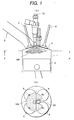
- FIG. 1 is a first embodiment of a direct injection spark ignition engine based on the present invention.
- Engine 1 has an air intake port 3 and an exhaust port 4, wherein the intake port 3 and the exhaust port 4 are connected through an intake valve 5 and an exhaust valve 6, respectively, to a combustion chamber 680.
- Numeral 2 is a piston
- numeral 20 is an ignition plug provided above the combustion chamber
- numeral 10 is an injector for injecting the fuel directly into the combustion chamber.
- This engine is a center injection type of direct injection engine injecting the fuel from nearly the center of the combustion chamber towards the piston.
- the spray of fuel injected from the injector has, for example, the partially incomplete hollow conical shape of a swirl type injector as shown in FIG. 20. That is to say, the present embodiment is characterized in that this spray of fuel consists of a dense fuel portion and a coarse-grained fuel portion, with the coarse-grained fuel portion being directed towards the ignition plug.
- spray angle "b” should be almost the same as the angle "a” formed between the injection hole of the injector and the electrode of the ignition plug
- the spray angle can be adjusted in the range of 0 to 30 degrees, which allows for the upward spread, and the diffusion, of the spray and prevents the fuel from sticking to the wall surface of the combustion chamber geometrically.
- a spray container measuring at least 300mm in diameter and at least 300mm high is injected with 15mcc/st of fuel, halogen light about 5mm thick is irradiated from two directions facing one another, at a distance of 40mm from the injection point on a cross section vertical to the central axis of the injector.
- An image of the light which has scattered from the spray of fuel on that cross section is captured using a high-sensitivity camera positioned on the central axis of the injector.
- the shutter of the camera is set to an open status to prevent unnecessary light from entering.
- the diaphragm is adjusted for the maximum brightness achievable in the range which does not cause halation.
- the inside of the circle which encompasses the portion of 30% or more of Imax at the maximum distance from the spraying point, with this point as the center, is defined as the spray zone, by which the spray angle is verified.
- spraying based on the present invention reduces the inside and outside spraying pressure difference because of air flowing from the coarse-grained spray portion into the spray, and hereby enables the spray angle to be maintained in a wide range, even under high-load conditions.
- the concentration of the spray is avoided and the fuel is widely distributed in the combustion chamber, with the result that the mixing of the fuel with ambient air is accelerated.
- the tumble created spontaneously by the shape of the intake ports functions to further accelerate air-fuel mixing.
- the coarse-grained portion of the spray is directed towards the ignition plug, the amount of liquid fuel sticking to the plug can be reduced.
- the time during which the combustible mixture exists near the ignition plug prolongs and a long ignition-enabling period can be achieved. Also, when the sprayed fuel dwells near the ignition plug, an ideal stratified mixture free of sticking to wall surfaces will be formed, which will enable fuel usage without waste, and hence, lean burning of the air-fuel mixture.
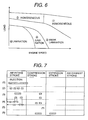
- FIG. 5 shows the operational status of the engine, namely, the relationship plotted with engine speed and load along the horizontal and vertical axes, respectively.
- stratified combustion can be executed, even in the region of relative high engine speeds where the combustion has formerly been difficult, and the stratified operating region where fuel consumption improves can be broadened.
- Homogeneous combustion also reduces fuel sticking to wall surfaces and enables the region to be broadened because of the mixture being homogenized.
- combustion can be stratified without depending on air flow, flow creating components are not required and costs can be reduced.
- FIG. 6 shows stratified and homogeneous operating regions under the relationship between engine speed and load.
- region 1 batch injection is started from the air intake stroke for the reason of limited time, as shown in FIG. 7 (1).
- the injection start timing is between 0-degree and 180-degree ATDC of the intake stroke, preferably, at or after 60-degree BTDC where the spray can follow up with the movement of the piston and the sticking of the fuel to wall surfaces can be reduced.
- center injection does not cause the diffusion of the spray to be hindered by strong air flow, and for this reason, the mixture spreads out in the entire combustion chamber as shown in FIG. 8 (1), with the result that excellent combustion characteristics can be obtained.
- Oil dilution and the occurrence of HC due to the sticking of fuel to the wall surfaces of the cylinder can also be suppressed. Even if the fuel sticks to the crown surface of the piston, since the piston itself is very hot under the operating conditions of region 1, it is likely that the sticking fuel will be vaporized before being ignited and that the exhaust performance of the engine will not be affected significantly.
- region 2 fuel is injected in split operations during the air intake stroke.
- the splitting of the injection into a plurality of operations accelerates the diffusion of the mixture, and the reduction of spray penetration per injection operation reduces the amount of fuel sticking to the crown surface of the piston and suppresses the occurrence of HC and smoke.
- the injection be split into operations as many as possible within an injection period close to its minimum value of Tmin with which, as shown in FIG. 9, the required quantity of injection is guaranteed.
- fuel is injected in two split operations and in this case, first injection is conducted from the air intake stroke to the first half of the compression stroke and second injection occurs during the second half of the compression stroke.
- Second injection time period T2 can take its minimum value with which an ignitable mixture can be formed, and the remainder is assigned to the first injection and the mixture is sufficiently vaporized.
- the first injection be conducted as early as possible during the air intake stroke, namely, at the timing between about 30- and 180-degree ATDC, within the range that the conditions under which the sprayed fuel does not collide with the piston are satisfied.
- the second injection timing should be set to the level between 270-degree and 340-degree ATDC of the compression stroke that enables fuel stratification near the plug.
- the injection does not need to be conducted in two split operations, and it can be conducted in more split operations for further accelerated mixing.
- the mixture can be distributed over the entire combustion chamber by splitting the first injection during the intake stroke.
- the second injection described above means the final injection.
- first injection period D1 and second injection period D2 are set to almost the same time period, with the result of the respective sprays being overlapped for further stratification as shown in FIG. 8 (4).
- the stratified operating region can be broadened.
- the diffusion of sprays can be controlled, even in the case of batch injection, by setting the injection timing to a level below the high direct pressure during the second half of the compression stroke.
- ignition timing is delayed, which improves combustion efficiency and, hence, fuel consumption. Furthermore, it is effective to set a high direct pressure, even for the same injection timing, and suppress the diffusion of sprays, by opening the throttle and forming a lean mixture from about 40 to 100 in terms of air-fuel ratio.
- Increasing the throttle angle reduces the restriction loss of the intake ports and improves fuel consumption.
- it is also effective to adopt supercharging with a supercharger, and even if the injection timing is advanced, the high direct pressure will suppress the diffusion of sprays and the long time from injection to ignition will accelerate vaporization.
- the injector needs to be driven at high speed. Therefore, it is valid to combine an injector that can be driven using a battery whose recharging is not required, or a rapid-response injector that uses piezoelectric elements/magnetostrictive elements.
- the fuel supply pressure increases 10 to 20 MPa to accelerate atomization.
- the increase in the supply pressure increases the injection ratio and correspondingly reduces the injection period, with the consequence that the suppression of penetration and the homogenization of the combustion chamber internal status can be realized by employing split injection formerly difficult because of limited time.
- the injection period can be prolonged by reducing the supply fuel pressure to a level of 1 to 5 MPa to enable split injection.
- swirling creates, just like the eye of a severe tropical storm, a weak flow of air in the center of the injector-equipped combustion chamber and enables the air-fuel mixture to be retained without being diffused like a tumble. For stratification, therefore, swirling is desirable.
- Such cavity as shown in FIG. 12 can also be provided in the piston to prevent the mixture from diffusing.
- the fuel should not stick, if the sprayed fuel collides with the piston during stratified combustion and the piston has a flat surface, it is likely that the fuel will diffuse into the combustion chamber along the crown surface of the piston and thus that a mixture will be formed in the quench layer.
- the spayed fuel With a cavity, the spayed fuel can be swirled upward in the direction of the plug along the curves of the wall surfaces and consequently, the mixture can be stratified more easily.
- the edge angle ⁇ of the cavity and the depth H thereof affect the formation of the mixture. Since ⁇ determines the direction in which the sprayed fuel will be headed after flowing out from the cavity, ⁇ should be set to an angle of 70 to 150 degrees at which the mixture can be transported in the direction of the plug. It is desirable that in view of cooling loss, the depth H of the cavity should be a small value.
- the distance from the top face of the combustion chamber and/or the configuration in the mounting direction can also be changed. It is possible to mount the ignition plug between two air intake valves. Also, although the present embodiment relates to a four-valve engine, it is possible to reduce the number of valves to two or three and make effective use of the resulting spatial margin around the cylinder head to arrange the injector and the plug there.
- the mixture can be transported to the ignition plug more easily by mounting the injector at a distance of about 0 to 40mm from the position of the ignition plug and positioning the plug at where the sprayed fuel will be swirled upward by friction with ambient air.
- Engine control unit (ECU) 710 after receiving an air intake rate control signal, an engine coolant temperature control signal, a fuel temperature control signal, a fuel pressure control signal, an engine speed control signal, a load control signal, a throttle angle control signal, a crank angle control signal, an air-fuel ratio control signal, an exhaust temperature control signal, and other control signals from the engine-mounted sensors as shown in FIG. 13, identifies the status of the engine.
- ECU Engine control unit
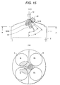
- FIG. 15 A second embodiment of the present invention is shown in FIG. 15.
- the second embodiment relates to a center injection type of direct injection engine having an injector disposed near the center of its combustion chamber, and in this engine, the portion of the injector that corresponds to the spray concentrating portion of such spray pattern as shown in FIG. 20 is disposed so as to face in the direction of the ignition plug, at the opposite side to the portion corresponding to the notched spray portion of the spray pattern.
- the spray angle "b" of the fuel with respect to the angle "a” formed between the injection hole of the injector and the electrode of the ignition plug is set to a small value from 10 to 30 degrees in order to avoid the collision of the fuel with the ignition plug.
- FIG. 16 A portion at which the sprayed fuel concentrates and its velocity increases is taken as spray 101A, and a portion provided at the side facing the above-mentioned portion and at which the velocity of the sprayed fuel decreases is taken as spray 101B.
- FIG. 17 A block diagram of a third embodiment is shown in FIG. 17, wherein the injector and the ignition plug are integrated into a single unit.
- the coarse-grained portion of the sprayed fuel is directed towards the electrode portion of the ignition plug to prevent a liquid fuel from directly striking the ignition plug. Description of working effects is omitted since they are almost the same as those of the first embodiment.
- FIG. 18 is a block diagram of the injector used in the above embodiment. The operation of the injector is described below.
- Valve body 14 when losing the valve, is sealed by being pressed against valve seat 16 by the action of a spring 60.
- a magnetic circuit is formed by a coil unit 61 and as a result, electromagnetic force is generated in the direction that the magnetic portion 62 of valve body 14 is to be lifted.
- valve body moves upward.
- Fuel flows in from the top of the injector, then passes through the internal channel 63 of the valve body, and arrives at nozzle 11.
- the nozzle contains a swirler 12 for rotating the fuel, and the fuel flows through a groove 13 provided in the swirler and is injected from the clearance between valve body 14 and valve seat 15 via injection hole 16 into the combustion chamber.
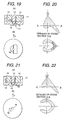
- Nozzle shape 1 of the injector is shown in FIG. 19.
- This nozzle has a level difference 17 in the half portion of the injection hole.
- a discontinuous portion is formed in a portion of the hollow spray of fuel injected from the conventional rotational-type injector, and consequently, coarse and dense portions occur in the distribution of sprays.
- FIG. 20 shows the spray pattern created from the injection hole of FIG. 11, with the upper diagram showing the spray pattern in vertical section and the lower diagram showing the pattern in horizontal section.
- One of the two sprays of fuel injected from this injector takes a discontinuous and coarse-grained status, and the other spray of fuel takes a dense status.
- the position and quantity of this coarse-and-dense distribution can be changed according to the particular size and position of the level difference provided in the nozzle.
- the first embodiment set forth above is intended to direct the coarse-grained spray portion towards the ignition plug, and the second embodiment is intended to direct the high-velocity dense spray portion, which is formed at the opposite side to the coarse-grained spray portion, towards the ignition plug.
- Nozzle shape 2 of the injector is shown in FIG. 21.
- a barrier 18 is formed at the outlet of the injection hole in order for the nozzle to have a shape as if a portion of a hollow conical spray of fuel were cut off at an angle of about 90 degrees as shown in FIG. 22.
- the portion corresponding to the coarse-grained cutoff portion of the spray is directed towards the ignition plug.
- Nozzle shape 3 of the injector is shown in FIG. 23.
- At least one or more barriers 19 are provided at a portion of the injection hole outlet, and a coarse-grained spray can likewise be formed by cutting off a portion of a spray of fuel as shown in FIG. 24.
- the size of the coarse-grained spray portion can be changed according to the particular width and height of each barrier. In this case as well, under the first embodiment, the portion corresponding to the coarse-grained cutoff portion of the spray is directed towards the ignition plug.
- Nozzle shape 4 of the injector is shown in FIG. 25.
- the nozzle portion 16 of the injector is porous and as shown in FIG. 26, coarse and dense sprays of fuel to be injected in a multitude of directions are formed.
- a variety of coarse and dense sprays of fuel can be formed according to the number of injection holes and the particular size and direction of the holes.
- the ignition plug is to be disposed at the portion corresponding to the coarse-grained spray of fuel between the sprays of fuel injected from each injection hole.
- the diameter of one, or more than one, injection hole is to be set to a value smaller than that of others and as shown in FIG. 28, the portion corresponding to a spray portion low in flow rate is to be directed towards the ignition plug.
- the diameter of one, or more than one, injection hole is to be set to a value larger than that of others and the portion corresponding to a spray portion high in velocity is to be directed towards the ignition plug at the angle that the plug will not be directly struck with the fuel.
- the flow of air is to be created inside the combustion chamber.
- the air-fuel mixture does not always need to be rotated upstream.
- the injector used in the present invention is provided with a means for determining the injector mounting position.
- the mounting hole for the injector also functions as a safety lock provided on the outer surface of the injector.
- the positioning means can likewise be constructed by providing a mark on the connector of the injector or on a separate injector, and a mark on the cylinder head. Marks can also be provided between adjacent ignition plug mounting holes. Such positioning guarantees that the coarse-grained spray portion of fuel is disposed at the position corresponding to the ignition plug without fail.
- the respective positions of the ignition plug and the injector should be set in order for the firing gap of the plug to face in the direction of the injector as represented in FIGS. 2 and 3.
- the plug can be mounted with such directivity since, as set forth above, the firing gap is not directly wetted with a liquid fuel. Hence, firing performance improves since a vaporized mixture is supplied directly to the firing gap.
- the fuel injector is constructed so that despite its installation in the vicinity of an ignition plug, the injector does not directly collide with the ignition plug, high exhaust performance and stratified combustion can be achieved without the ignition plug misfiring.
Landscapes
- Engineering & Computer Science (AREA)
- Chemical & Material Sciences (AREA)
- Combustion & Propulsion (AREA)
- Mechanical Engineering (AREA)
- General Engineering & Computer Science (AREA)
- Combustion Methods Of Internal-Combustion Engines (AREA)
- Fuel-Injection Apparatus (AREA)
- Ignition Installations For Internal Combustion Engines (AREA)
- Exhaust Gas After Treatment (AREA)
- Electrical Control Of Air Or Fuel Supplied To Internal-Combustion Engine (AREA)
Abstract
Description
- The present invention relates to a direct injection-type spark ignition engine that supplies a fuel directly to the inside of a combustion chamber.
- In conventional direct injection engines, the injector is provided at an angle from 20 to 50 degrees with respect to the horizontal face of the combustion chamber, under the air intake ports thereof.
- These engines are constructed so that during stratified combustion, a fuel is injected towards the cavity provided in the piston and then an air-to-fuel mixture is ignited by being introduced into the ignition plug located in the upper center of the combustion chamber, in combination with the air flow created by the flow creation means, such as swirl control valve, that is located at the intake ports.
- Japanese Application Patent Laid-Open Publication No. Hei 06-42352 describes art by which, in a center injection type of direct injection gasoline engine having an injector in the central top of the combustion chamber and injecting the fuel towards the piston, the ignition plug is struck directly with sprays of fuel and the density of the air-fuel mixture is controlled with high accuracy.
- Japanese Application Patent Laid-Open Publication No. Hei 10-131756 describes an engine which, as with the above art, is provided with an injector for injecting a fuel from nearly the top center of the combustion chamber towards the piston, with a cavity in the valve portion at the top of the piston, and with an ignition plug at where it is offset both inside the cavity and at the air intake valve end. Since the ignition plug is located so that sprays of fuel do not directly strike the plug, the shape of the piston and the flow of air ensure intensive supply of the mixture to the ignition plug and stabilize stratified combustion.
- However, for the center injection type of direct injection gasoline engine described in Japanese Application Patent Laid-Open Publication No. Hei 06-42352, since the ignition plug is struck with the fuel directly and actively, consideration is not given to the occurrence of a misfire due to the sticking of a liquid fuel to the plug, or to the deterioration of combustion stability, associated with the misfire.
- In addition, for the center injection type of direct injection gasoline engine described in Japanese Application Patent Laid-Open Publication No. Hei 10-131756, since the piston shape and the flow of air are optimized to stratify the mixture, the occurrence of unburnt hydrocarbon, soot, and the like due to the combustion of any fuel components sticking to the piston is likely to deteriorate exhaust performance. Furthermore, there are the problems that a flow creation means, piston machining, and sophisticated control are required and that the costs are high.
- The present invention is intended to solve the above-mentioned problems associated with the prior art, and an object of the invention is to prevent the ignition plug from being directly struck with a liquid fuel, by optimizing the fuel spraying pattern and thus to suppress the misfiring of the ignition plug and the instability of combustion, associated therewith.
- Another object of the invention is to provide a spraying control means for stabilizing combustion, by minimizing the support of the air flow and piston shape and achieving stratification based on spraying characteristics.
- In a direct injection type of spark ignition internal-combustion engine which injects gasoline directly into the combustion chamber and has an injector near the upper center thereof and an ingition plug in the neighborhood of the injector, an injector for creating coarse-grained and dense sprays of fuel may be combined and the coarse-grained spray can be directed towards the ignition plug.
- In a direct injection type of spark ignition internal-combustion engine which injects gasoline directly into the combustion chamber and has an injector near the upper center thereof and an ignition plug in the neighborhood of the injector, an injector for creating coarse-grained and dense sprays of fuel may be combined and the sense spray can be directed towards the bottom of the ignition plug.
- The injector described above may have the structure where it has a stepped portion in the direction of the injector central axis at the open exit end of the injection hole.
- The injector described above may have the structure where it has a multitude of injection holes.
- The injector described above may have the structure where a portion of the injection hole is provided with a shielding plate to cut a portion of the spray.
- In the injector structure described aboe, the injector and the ignition plug may be integrated into a single unit.
- In the direct injection internal-combustion engine described above, gasoline may be injected a plurality of times during one cylce consisting of air intake, compression, expansion, and exhaust.
-
- FIG. 1 (a) is a cross-sectional view of the engine pertaining to a first embodiment, and FIG. 1 (b) is a view of cross section (a) above when seen from the direction of arrow-marked line P-P';
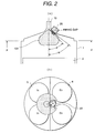
- FIG. 2 (a) is an explanatory view of the stratified-mixture distribution pertaining to the first embodiment, and FIG. 2 (b) is a view of distribution (a) above when seen from the direction of arrow-marked line P-P';
- FIG. 3 (a) is an explanatory view of the homogeneous-mixture distribution obtained during the initial phase of spraying based on the first embodiment, and FIG. 3 (b) is an explanatory view of the mixture distribution obtained toward the end of spraying;
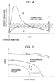
- FIG. 4 is an explanatory diagram of changes in the mixture density near the plug;
- FIG. 5 is an operational characteristics curve explaining the broadening effects of stratification and homogeneous operating regions;
- FIG. 6 is a chart explaining the relationship between stratification and homogeneous operating regions and an injection control method;
- FIG. 7 is a diagram explaining the injection timing in each region of FIG. 6;
- FIG. 8 is a set of views explaining the behavior of a mixture inside the combustion chamber during injection control;
- FIG. 9 is a graph explaining the relationship between injection period and fuel flow rate;
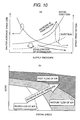
- FIG. 10 (a) is a chart explaining the relationship between fuel pressure, average grain size, and spray penetration, and FIG. 10 (b) is a diagram explaining the relationship between air flow and fuel pressure, based on the operating conditions of the engine;
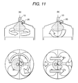
- FIG. 11 is a set of views which explain combinations of air flow and fuel injection control based on the present invention; (a) explaining a combination with a swirl (lateral swirling flow) and (b) explaining a combination with a tumble (longitudinal swirling flow);
- FIG. 12 is a diagram explaining an application of the present invention using a piston equipped with a cavity;
- FIG. 13 is a block diagram showing the input and output signals of an engine control unit;
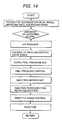
- FIG. 14 is a flowchart showing an example of operation up to completion of injection;
- FIG. 15 (a) is a cross-sectional view of the engine pertaining to a second embodiment, and FIG. 15 (b) is a view of cross section (a) above when seen from the direction of arrow-marked line P-P';
- FIG. 16 (a) is an explanatory view of the mixture distribution obtained during the initial phase of spraying based on the first embodiment, and FIG. 16 (b) is an explanatory view of the mixture distribution obtained toward the end of spraying;
- FIG. 17 (a) is a cross-sectional view of the engine pertaining to a third embodiment, and FIG. 17 (b) is a view of cross section (a) above when seen from the direction of arrow-marked line P-P';
- FIG. 18 (a) is a cross-sectional view of the injector pertaining to the present invention, and FIG. 18 (b) is a view of injector (a) above when seen from the direction of arrow-marked line A-A';
- FIG. 19 (a) is an enlarged cross-sectional view of the end portion of the injector used in the first embodiment, and FIG. 19 (b) is a cross-sectional view of end portion (a) above when seen from the direction of arrow P;
- FIG. 20 is a set of views showing the spray pattern of the fuel injected from the injector of FIG. 19;
- FIG. 21 (a) is an enlarged cross-sectional view of the end portion of the injector used in the second embodiment, and FIG. 21 (b) is a cross-sectional view of end portion (a) above when seen from the direction of arrow P;
- FIG. 22 is a set of views showing the spray pattern of the fuel injected from the injector of FIG. 21;
- FIG. 23 (a) is an enlarged cross-sectional view of the end portion of the injector of FIG. 18 in the third embodiment, and FIG. 23 (b) is a cross-sectional view of end portion (a) above when seen from the direction of arrow P;
- FIG. 24 is a set of views showing the spray pattern of the fuel injected from the injector of FIG. 23;
- FIG. 25 (a) is an enlarged cross-sectional view of the end portion of the injector of FIG. 18 in a fourth embodiment, and FIG. 25 (b) is a cross-sectional view of end portion (a) above when seen from the direction of arrow P;
- FIG. 26 is a set of views showing the spray pattern of the fuel injected from the injector of FIG. 25;
- FIG. 27 (a) is an enlarged cross-sectional view of the end portion of the injector of FIG. 18 in a fifth embodiment, and FIG. 27 (b) is a cross-sectional view of end portion (a) above when seen from the direction of arrow P;
- FIG. 28 is a set of views showing the spray pattern of the fuel injected from the injector of FIG. 27; and
- FIG. 29 is a total explanatory diagram of a system in which the present invention is embodied.
-
- The entire system where the present invention is embodied is described below per FIG. 29.
- The air intake circuit comprises an
air flow sensor 310 for measuring the air intake rate, anelectronic control throttle 320 for controlling the air intake rate, athrottle angle sensor 521 for detecting the angle of opening of the throttle, an airflow control valve 330 for creating a tumble (longitudinal swirling flow) within thecylinder 680, apartition plate 340 for separating vertically the air intake channel located under valve 330 (this partition plate is referred to as the double-stepped intake port), andintake valves 5. - Also, a
supercharger 421 is mounted betweenair flow sensor 310 andelectronic control throttle 320 and rotated by anexhaust gas turbine 480 located in the exhaust channel. - The exhaust circuit comprises an air-
fuel ratio sensor 410 andcatalytic converter rhodium 420, which are located in order at the bottom ofexhaust valves 6, and anexhaust turbine 480, anexhaust temperature sensor 430, anNOx catalyst 440, and anoxygen concentration sensor 450, which are mounted in parallel with thecatalytic converter rhodium 420. Achannel 460 for circulating a portion of a combustion exhaust gas from the upstream end of air-fuel ratio sensor 410 to anintake tube collector 360 is also provided so that the NOx emission level is controlled by the recirculation of the exhaust gas. - In addition, an
EGR valve 470 for controlling the quantity of circulation of the exhaust gas is provided halfway in thechannel 460. Furthermore, an opening/closing valve 490 is mounted at the inlet ofexhaust turbine 420 to accelerate early activation ofcatalytic converter rhodium 420 by blocking the exhaust gas so that it does not flow intoexhaust turbine 480 during the start of the engine. - The fuel circuit comprises a fuel injector 10 (in the following description of embodiments, referred to simply as the injector) mounted adjacently to
ignition plug 20, a low-pressure feed pump 510 for pumping up a fuel from afuel tank 500, a high-pressure fuel pump 520 andfuel pipeline 540 for increasing the low fuel pressure and supplying the fuel toinjector 10, afuel pressure sensor 530 installed on acommon rail 531 to measure the fuel pressure, a variable-capacity control valve 521 mounted in the intake channel of the high-pressure fuel pump to control the fuel discharge thereof, and afuel temperature sensor 520 for detecting the fuel temperature. - The ignition circuit comprises an
ignition plug 20 installed at the top of a cylinder, and an independent ignition type of igniter-equippedignition coil unit 750 for supplying a firing high voltage toignition plug 20. - The
piston 2 ofengine 1 has a cavity-less flat shape, and swirlingair stream 670 withincylinder 680 flows in from a pair ofair intake valves 5 provided acrossignition plug 20 and then while heading for the bottom of twoexhaust valves 6 and the top ofpiston 2, both streams flow together to form a single forward tumble (longitudinal swirling flow) 670. - After this, the tumble flows into the
intake valves 5 along the top ofpiston 2 and the resulting two streams change into the single air flow that ascends towards the clearance between the twointake valves 5. The corresponding intake air flow, after flowing under theinjector 10 and theignition plug 20, further flows under the clearance between two exhaust valves 400 and both streams flow together as theoriginal tumble 670. -
Control unit 710 properly controls the internal combustion of the internal-combustion engine by receiving operational information from various exhaust sensors such asair flow sensor 310,throttle angle sensor 321, crank angle sensor, accelerator pedal sensor, air-fuel ratio sensor 410,fuel temperature sensor 520, andfuel pressure sensor 530, and then sending signals to components such aselectronic control throttle 320,injector 10,EGR valve 470, variable-capacity control valve 521, the igniter ofignition coils 750, opening/closingvalve 490, and airflow control valve 330. - There are two major methods of controlling combustion: stratified combustion and homogeneous combustion.
- Stratified combustion is a combustion control method in which the sprayed fuel is to be stratified and ignited by injecting the fuel under the status that the pressure inside the
cylinder 680 during the second half of its compression stroke has increased, and converging the combustible mixture at a position near theignition plug 20. The stratification of the sprayed fuel enables combustion to take place insidecylinder 680 under a lean status equivalent to an air-fuel ratio of about 40, and thus improves fuel consumption. - Homogeneous combustion is a combustion control method in which the fuel is to be mixed with air into homogeneity during the air intake stroke of the cylinder before being ignited. Since the fuel is injected so that the air-fuel ratio inside the
entire cylinder 680 becomes almost the same as a theoretical value, this method ensures high-output operation compared with the operation of the stratified lean-burn engine described above. - The spray of
fuel 100 frominjector 10 is injected from the upper wall center of the cylinder towardspiston 2. - FIG. 1 is a first embodiment of a direct injection spark ignition engine based on the present invention.
Engine 1 has anair intake port 3 and anexhaust port 4, wherein theintake port 3 and theexhaust port 4 are connected through anintake valve 5 and anexhaust valve 6, respectively, to acombustion chamber 680.Numeral 2 is a piston, numeral 20 is an ignition plug provided above the combustion chamber, and numeral 10 is an injector for injecting the fuel directly into the combustion chamber. - This engine is a center injection type of direct injection engine injecting the fuel from nearly the center of the combustion chamber towards the piston. The spray of fuel injected from the injector has, for example, the partially incomplete hollow conical shape of a swirl type injector as shown in FIG. 20. That is to say, the present embodiment is characterized in that this spray of fuel consists of a dense fuel portion and a coarse-grained fuel portion, with the coarse-grained fuel portion being directed towards the ignition plug.
- Also, as shown in FIG. 2, although it is desirable that spray angle "b" should be almost the same as the angle "a" formed between the injection hole of the injector and the electrode of the ignition plug, the spray angle can be adjusted in the range of 0 to 30 degrees, which allows for the upward spread, and the diffusion, of the spray and prevents the fuel from sticking to the wall surface of the combustion chamber geometrically.
- The method of verifying the spray of fuel is described below. A spray container measuring at least 300mm in diameter and at least 300mm high is injected with 15mcc/st of fuel, halogen light about 5mm thick is irradiated from two directions facing one another, at a distance of 40mm from the injection point on a cross section vertical to the central axis of the injector.
- An image of the light which has scattered from the spray of fuel on that cross section is captured using a high-sensitivity camera positioned on the central axis of the injector. The shutter of the camera is set to an open status to prevent unnecessary light from entering. Also, the diaphragm is adjusted for the maximum brightness achievable in the range which does not cause halation. When the maximum luminance of the captured spray image is taken as Imax, the portion of 30% or less of Imax in terms of luminance and the portion of 70% or more of Imax are defined as a coarse-grained spray portion and a dense spray portion, respectively.
- Also, the inside of the circle which encompasses the portion of 30% or more of Imax at the maximum distance from the spraying point, with this point as the center, is defined as the spray zone, by which the spray angle is verified.
- Next, the operation and working effects of this direct injection engine are described below. In medium/high-load operation of the direct injection engine, fuel is injected during the air intake stroke of the cylinder and a homogeneous mixture is formed, ignited, and burnt. In the present embodiment, since the central axis of the combustion chamber and that of spraying match, the sticking of the fuel to the side walls of the cylinder can be suppressed by spreading out the sprayed fuel in the entire combustion chamber as shown in FIG. 3 (a).
- In addition, although conventional hollow conical spraying has the tendency that when the injection period prolongs during high-load operation, the difference between the inside and outside spraying pressures will reduce the spray angle and the fuel will concentrate on the center of the spray, spraying based on the present invention reduces the inside and outside spraying pressure difference because of air flowing from the coarse-grained spray portion into the spray, and hereby enables the spray angle to be maintained in a wide range, even under high-load conditions.
- Thus, as shown in FIG. 3 (b), the concentration of the spray is avoided and the fuel is widely distributed in the combustion chamber, with the result that the mixing of the fuel with ambient air is accelerated. Even without a flow creating means, the tumble created spontaneously by the shape of the intake ports functions to further accelerate air-fuel mixing. Also, since the coarse-grained portion of the spray is directed towards the ignition plug, the amount of liquid fuel sticking to the plug can be reduced.
- In this way, since neither the ignition plug nor the side walls of the combustion chamber are not directly struck with the liquid fuel, the sticking of the liquid fuel to the combustion chamber interior can be reduced, and since the release of HC, soot, and the like improves and this reduces the amount of fuel left in the quench layer, output and fuel consumption also improve.
- In low-load operation, on the other hand, as shown in FIG. 2, fuel is injected during the second half of the compression stroke of the cylinder and a mixture is stratified near the plug, with the result that when totally viewed, the air-fuel mixture is burnt under its lean status. Time-varying changes in the mixture density near the ignition plug during compression stroke injection are shown in FIG. 4.
- For the hollow conical spray that is formed by a swirl-type injector based on prior art, since the use of wide-angle spraying causes the injected fuel to collide directly with the ignition plug, the liquid fuel directly strikes and sticks to the ignition plug and as a result, the mixture near the plug temporarily assumes an over-dense status.
- When droplets of liquid fuel collide with the ignition plug, a liquid membrane will be formed and the liquid fuel that is not vaporized before ignition begins will be burnt intact. This will not only deteriorate exhaust performance, but also cause the ignition plug to misfire because of a combustion product sticking to the plug. The use of coarse-grained and dense spraying based on the present embodiment does not cause the ignition plug to be directly struck with fuel, and therefore, although the mixture density near the ignition plug decreases immediately after injection, the misfiring of the plug can be prevented.
- Under the high-pressure atmosphere in the second half of the compression stroke, the penetration of the spray becomes weak and the spray dwells in the center of the combustion chamber, with the result that the mixture, after being vaporized and diffused with the elapse of time, arrives at the ignition plug as a combustible mixture.
- Accordingly, as denoted by
numeral 51, the time during which the combustible mixture exists near the ignition plug prolongs and a long ignition-enabling period can be achieved. Also, when the sprayed fuel dwells near the ignition plug, an ideal stratified mixture free of sticking to wall surfaces will be formed, which will enable fuel usage without waste, and hence, lean burning of the air-fuel mixture. - In other words, engine structure based on the present embodiment improves fuel consumption, even during stratified combustion, and enables the emission of unburnt hydrocarbon and other substances to be reduced and the misfiring of the ignition plug to be prevented. FIG. 5 shows the operational status of the engine, namely, the relationship plotted with engine speed and load along the horizontal and vertical axes, respectively.
- In the present embodiment, since the time required for the mixture to flow from the injector to the ignition plug does not need to be considered, stratified combustion can be executed, even in the region of relative high engine speeds where the combustion has formerly been difficult, and the stratified operating region where fuel consumption improves can be broadened.
- Homogeneous combustion also reduces fuel sticking to wall surfaces and enables the region to be broadened because of the mixture being homogenized. In addition, since combustion can be stratified without depending on air flow, flow creating components are not required and costs can be reduced.
- The method of injection control in a center injection type of direct injection engine using the above-described injector is described below. Exhaust performance, fuel consumption, and other engine performance characteristics can be improved by conducting injection control in the engine structure described above.
- FIG. 6 shows stratified and homogeneous operating regions under the relationship between engine speed and load. In the high-load high-speed homogeneous operating region shown as
region 1, batch injection is started from the air intake stroke for the reason of limited time, as shown in FIG. 7 (1). - The injection start timing is between 0-degree and 180-degree ATDC of the intake stroke, preferably, at or after 60-degree BTDC where the spray can follow up with the movement of the piston and the sticking of the fuel to wall surfaces can be reduced. Unlike side injection, center injection does not cause the diffusion of the spray to be hindered by strong air flow, and for this reason, the mixture spreads out in the entire combustion chamber as shown in FIG. 8 (1), with the result that excellent combustion characteristics can be obtained.
- Oil dilution and the occurrence of HC due to the sticking of fuel to the wall surfaces of the cylinder can also be suppressed. Even if the fuel sticks to the crown surface of the piston, since the piston itself is very hot under the operating conditions of
region 1, it is likely that the sticking fuel will be vaporized before being ignited and that the exhaust performance of the engine will not be affected significantly. - In the low/medium-speed high-load operating region shown as
region 2, fuel is injected in split operations during the air intake stroke. The splitting of the injection into a plurality of operations accelerates the diffusion of the mixture, and the reduction of spray penetration per injection operation reduces the amount of fuel sticking to the crown surface of the piston and suppresses the occurrence of HC and smoke. - It is desirable that the injection be split into operations as many as possible within an injection period close to its minimum value of Tmin with which, as shown in FIG. 9, the required quantity of injection is guaranteed.
- Thereby, as shown in FIG. 8(2), the fuel that has been injected during the first half of the intake stroke is distributed in the lower section of the combustion chamber and the fuel that has been injected during the second half of the intake stroke is distributed in the upper section of the combustion chamber, with the result that the nonuniformity of the mixture can be reduced.
- In the weak stratification region shown as
region 3, fuel is injected in two split operations and in this case, first injection is conducted from the air intake stroke to the first half of the compression stroke and second injection occurs during the second half of the compression stroke. - As shown in FIG. 8 (3), a homogeneous lean mixture that permits flames to propagate into the combustion chamber is formed during the first injection, and the second injection is stratified near the plug and ignites the mixture. Second injection time period T2 can take its minimum value with which an ignitable mixture can be formed, and the remainder is assigned to the first injection and the mixture is sufficiently vaporized.
- It is desirable that the first injection be conducted as early as possible during the air intake stroke, namely, at the timing between about 30- and 180-degree ATDC, within the range that the conditions under which the sprayed fuel does not collide with the piston are satisfied. The second injection timing should be set to the level between 270-degree and 340-degree ATDC of the compression stroke that enables fuel stratification near the plug.
- Also, the injection does not need to be conducted in two split operations, and it can be conducted in more split operations for further accelerated mixing. In the latter case, the mixture can be distributed over the entire combustion chamber by splitting the first injection during the intake stroke. In the case of multiple injection operations, the second injection described above means the final injection.
- In the low/medium-speed stratification region shown as
region 4, fuel is injected in split operations during the compression stroke as shown in FIG. 7 (4). The injection period per operation is shortened to reduce spray penetration, and first injection period D1 and second injection period D2 are set to almost the same time period, with the result of the respective sprays being overlapped for further stratification as shown in FIG. 8 (4). Thus, the stratified operating region can be broadened. - In the low/medium-speed stratification region shown as
region 5, as withregion 4, although injection can be split during the compression stroke, the diffusion of sprays can be controlled, even in the case of batch injection, by setting the injection timing to a level below the high direct pressure during the second half of the compression stroke. - In addition to the injection timing, ignition timing is delayed, which improves combustion efficiency and, hence, fuel consumption. Furthermore, it is effective to set a high direct pressure, even for the same injection timing, and suppress the diffusion of sprays, by opening the throttle and forming a lean mixture from about 40 to 100 in terms of air-fuel ratio.
- Increasing the throttle angle reduces the restriction loss of the intake ports and improves fuel consumption. To further increase the direct pressure, it is also effective to adopt supercharging with a supercharger, and even if the injection timing is advanced, the high direct pressure will suppress the diffusion of sprays and the long time from injection to ignition will accelerate vaporization.
- To implement multiple-split injection described above, the injector needs to be driven at high speed. Therefore, it is valid to combine an injector that can be driven using a battery whose recharging is not required, or a rapid-response injector that uses piezoelectric elements/magnetostrictive elements.
- Next, the method of controlling the supply fuel pressure is described below. For the engine structure described above, since the injection point and the ignition point are close, it is desirable that the fuel that has been atomized from the initial period of injection should be supplied for accelerated vaporization.
- As shown in FIG. 10, atomization and spray penetration are maintained in the trade-off relationship that although an increase in fuel supply pressure usually accelerates atomization, penetration increases correspondingly. To reduce spray penetration, it is valid to inject the fuel in multiple split operations as described above. Split injection reduces penetration while at the same time maintaining the grain size of the sprayed fuel, as shown in the figure.
- During high-speed homogeneous rotation in
region 1, since a sufficient vaporizing time cannot be obtained, the fuel supply pressure increases 10 to 20 MPa to accelerate atomization. The increase in the supply pressure increases the injection ratio and correspondingly reduces the injection period, with the consequence that the suppression of penetration and the homogenization of the combustion chamber internal status can be realized by employing split injection formerly difficult because of limited time. - During medium/low-speed homogeneous rotation in
region 2, weak stratification rotation inregion 3, and medium-speed rotation inregion 4, above-mentioned split injection occurs at ordinary fuel pressure from 5 to 12 MPa. - During low-speed homogeneous rotation in
region 5, although split injection has formerly been difficult because of a short injection period, the injection period can be prolonged by reducing the supply fuel pressure to a level of 1 to 5 MPa to enable split injection. - Although the reduction of the fuel pressure deteriorates performance in terms of grain size, since low-speed rotation permits the extension of the time from injection to ignition, a large portion of the fuel can be vaporized before ignition is started, provided that stratification near the plug can be maintained. Also, the degree of stratification can be enhanced by overlapping the sprays of fuel by use of split injection.
- Next, the control of air flow is described. Assigning air flow to the engine described above enables engine performance to be improved.
- When lateral swirling air flow is assigned to the combustion chamber as shown in FIG. 11 (a), the sticking of the fuel to wall surfaces during homogeneous combustion in
regions - In the case of stratified combustion in
regions - In addition, swirling creates, just like the eye of a severe tropical storm, a weak flow of air in the center of the injector-equipped combustion chamber and enables the air-fuel mixture to be retained without being diffused like a tumble. For stratification, therefore, swirling is desirable.
- The same also applies when, as shown in FIG. 11 (b), a tumble, or a vertical vortex, is assigned, and during homogeneous combustion, mixing is accelerated and during stratified combustion, the mixture is transported to the plug. For split injection in stratified combustion mode, however, a weak flow of air needs to be assigned, since the mixture is transported to the exhaust circuit without dwelling halfway.
- Such cavity as shown in FIG. 12 can also be provided in the piston to prevent the mixture from diffusing. Although it is desirable that the fuel should not stick, if the sprayed fuel collides with the piston during stratified combustion and the piston has a flat surface, it is likely that the fuel will diffuse into the combustion chamber along the crown surface of the piston and thus that a mixture will be formed in the quench layer.
- With a cavity, the spayed fuel can be swirled upward in the direction of the plug along the curves of the wall surfaces and consequently, the mixture can be stratified more easily.
- At this time, the edge angle of the cavity and the depth H thereof affect the formation of the mixture. Since determines the direction in which the sprayed fuel will be headed after flowing out from the cavity, should be set to an angle of 70 to 150 degrees at which the mixture can be transported in the direction of the plug. It is desirable that in view of cooling loss, the depth H of the cavity should be a small value.
- In terms of the relationship in mounting position between the injector and ignition plug, the distance from the top face of the combustion chamber and/or the configuration in the mounting direction can also be changed. It is possible to mount the ignition plug between two air intake valves. Also, although the present embodiment relates to a four-valve engine, it is possible to reduce the number of valves to two or three and make effective use of the resulting spatial margin around the cylinder head to arrange the injector and the plug there.
- In addition, the mixture can be transported to the ignition plug more easily by mounting the injector at a distance of about 0 to 40mm from the position of the ignition plug and positioning the plug at where the sprayed fuel will be swirled upward by friction with ambient air.
- Engine control unit (ECU) 710, after receiving an air intake rate control signal, an engine coolant temperature control signal, a fuel temperature control signal, a fuel pressure control signal, an engine speed control signal, a load control signal, a throttle angle control signal, a crank angle control signal, an air-fuel ratio control signal, an exhaust temperature control signal, and other control signals from the engine-mounted sensors as shown in FIG. 13, identifies the status of the engine.
- Then after analyzing the results, determines the appropriate injection timing, injection period, fuel pressure, air flow control valve angle, etc. from such map of injection method as shown in FIG. 6 and such map of air flow states and fuel pressures as shown in FIG. 10 (b), and sends the above-mentioned control signals to the engine control units in accordance with the flowchart of FIG. 14.
- A second embodiment of the present invention is shown in FIG. 15. As with the first embodiment, the second embodiment relates to a center injection type of direct injection engine having an injector disposed near the center of its combustion chamber, and in this engine, the portion of the injector that corresponds to the spray concentrating portion of such spray pattern as shown in FIG. 20 is disposed so as to face in the direction of the ignition plug, at the opposite side to the portion corresponding to the notched spray portion of the spray pattern.
- At this time, the spray angle "b" of the fuel with respect to the angle "a" formed between the injection hole of the injector and the electrode of the ignition plug is set to a small value from 10 to 30 degrees in order to avoid the collision of the fuel with the ignition plug.
- Working effects are described using FIG. 16. A portion at which the sprayed fuel concentrates and its velocity increases is taken as
spray 101A, and a portion provided at the side facing the above-mentioned portion and at which the velocity of the sprayed fuel decreases is taken asspray 101B. - As shown in FIG. 16(a), inside the combustion chamber,
air flow 30 from the ignition plug towards the piston is created from 101A, and as shown in FIG. 16 (b), 101B meetsflow 30 and both move to a position near the ignition plug. Since the flow is created from the spray, a vaporized mixture can be stratified at the ignition plug, even without initial flow of air. - Although 101A moves past the neighborhood of the ignition plug in dripping form, a misfire does not occur since the small spray angle prevents collision with the ignition plug. The portion actually used for ignition is 101B, and this portion is likely to be vaporized before it arrives at the ignition plug. It has been verified that the effectiveness of the present embodiment is much the same as that of the first embodiment.
- A block diagram of a third embodiment is shown in FIG. 17, wherein the injector and the ignition plug are integrated into a single unit. Although arranging the injector and the ignition plug on the cylinder head requires modifying the head extensively, the mounting spaces for the injector and ignition plug can be saved by integrating both.
- Similarly to this, in the configuration shown in FIG. 17, the coarse-grained portion of the sprayed fuel is directed towards the electrode portion of the ignition plug to prevent a liquid fuel from directly striking the ignition plug. Description of working effects is omitted since they are almost the same as those of the first embodiment.
- FIG. 18 is a block diagram of the injector used in the above embodiment. The operation of the injector is described below.
Valve body 14, when losing the valve, is sealed by being pressed againstvalve seat 16 by the action of aspring 60. When the valve opening signal is given from ECU, a magnetic circuit is formed by acoil unit 61 and as a result, electromagnetic force is generated in the direction that themagnetic portion 62 ofvalve body 14 is to be lifted. - Thus, the valve body moves upward. Fuel flows in from the top of the injector, then passes through the internal channel 63 of the valve body, and arrives at
nozzle 11. The nozzle contains aswirler 12 for rotating the fuel, and the fuel flows through agroove 13 provided in the swirler and is injected from the clearance betweenvalve body 14 andvalve seat 15 viainjection hole 16 into the combustion chamber. -
Nozzle shape 1 of the injector is shown in FIG. 19. This nozzle has alevel difference 17 in the half portion of the injection hole. In this configuration, a discontinuous portion is formed in a portion of the hollow spray of fuel injected from the conventional rotational-type injector, and consequently, coarse and dense portions occur in the distribution of sprays. - FIG. 20 shows the spray pattern created from the injection hole of FIG. 11, with the upper diagram showing the spray pattern in vertical section and the lower diagram showing the pattern in horizontal section. One of the two sprays of fuel injected from this injector takes a discontinuous and coarse-grained status, and the other spray of fuel takes a dense status.
- The position and quantity of this coarse-and-dense distribution can be changed according to the particular size and position of the level difference provided in the nozzle. The first embodiment set forth above is intended to direct the coarse-grained spray portion towards the ignition plug, and the second embodiment is intended to direct the high-velocity dense spray portion, which is formed at the opposite side to the coarse-grained spray portion, towards the ignition plug.
-
Nozzle shape 2 of the injector is shown in FIG. 21. Abarrier 18 is formed at the outlet of the injection hole in order for the nozzle to have a shape as if a portion of a hollow conical spray of fuel were cut off at an angle of about 90 degrees as shown in FIG. 22. In the first embodiment, the portion corresponding to the coarse-grained cutoff portion of the spray is directed towards the ignition plug. -
Nozzle shape 3 of the injector is shown in FIG. 23. At least one ormore barriers 19 are provided at a portion of the injection hole outlet, and a coarse-grained spray can likewise be formed by cutting off a portion of a spray of fuel as shown in FIG. 24. The size of the coarse-grained spray portion can be changed according to the particular width and height of each barrier. In this case as well, under the first embodiment, the portion corresponding to the coarse-grained cutoff portion of the spray is directed towards the ignition plug. -
Nozzle shape 4 of the injector is shown in FIG. 25. In this injector configuration, thenozzle portion 16 of the injector is porous and as shown in FIG. 26, coarse and dense sprays of fuel to be injected in a multitude of directions are formed. A variety of coarse and dense sprays of fuel can be formed according to the number of injection holes and the particular size and direction of the holes. - When this configuration is applied to the first embodiment, the ignition plug is to be disposed at the portion corresponding to the coarse-grained spray of fuel between the sprays of fuel injected from each injection hole. Or as shown in FIG. 27, the diameter of one, or more than one, injection hole is to be set to a value smaller than that of others and as shown in FIG. 28, the portion corresponding to a spray portion low in flow rate is to be directed towards the ignition plug.
- To apply the above configuration to the second embodiment, the diameter of one, or more than one, injection hole is to be set to a value larger than that of others and the portion corresponding to a spray portion high in velocity is to be directed towards the ignition plug at the angle that the plug will not be directly struck with the fuel. Thus, the flow of air is to be created inside the combustion chamber. In the case of the porous injector, the air-fuel mixture does not always need to be rotated upstream.
- The injector used in the present invention is provided with a means for determining the injector mounting position. For example, the mounting hole for the injector also functions as a safety lock provided on the outer surface of the injector.
- The positioning means can likewise be constructed by providing a mark on the connector of the injector or on a separate injector, and a mark on the cylinder head. Marks can also be provided between adjacent ignition plug mounting holes. Such positioning guarantees that the coarse-grained spray portion of fuel is disposed at the position corresponding to the ignition plug without fail.
- Furthermore, it is preferable that the respective positions of the ignition plug and the injector should be set in order for the firing gap of the plug to face in the direction of the injector as represented in FIGS. 2 and 3. In the present invention, the plug can be mounted with such directivity since, as set forth above, the firing gap is not directly wetted with a liquid fuel. Hence, firing performance improves since a vaporized mixture is supplied directly to the firing gap.
- In the present invention, since the fuel injector is constructed so that despite its installation in the vicinity of an ignition plug, the injector does not directly collide with the ignition plug, high exhaust performance and stratified combustion can be achieved without the ignition plug misfiring.
Claims (22)
- A direct injection gasoline engine (1) for directly injecting a fuel into a cylinder (680) from a fuel injector (10); said direct injection gasoline engine having said fuel injector (10) mounted in the neighborhood of an ignition plug (20), and being installed in such a manner that the fuel injector (10) is constructed so as to achieve a nonuniform fuel distribution in a circumferential direction with respect to the spraying axis of the fuel injector (10) and that the coarse portion of the distribution corresponds to said ignition plug (30).
- A fuel injector (10) to be used for a direct injection gasoline engine (1) which injects a fuel directly into a cylinder (680) from a fuel injector (10) mounted in the neighborhood of an ignition plug (20); said fuel injector (10) being constructed so as to achieve a nonuniform fuel distribution in a circumferential direction with respect to the spraying axis of the fuel injector (10), and being equipped with a means for positioning the fuel injector (10) so that when the engine (1) is mounted, the coarse-grained portion of the fuel sprayed will correspond to said ignition plug (20).
- A direct injection gasoline engine (1) for injecting a fuel directly into a cylinder (680) from a fuel injector (10); said direct injection gasoline engine (1) having said fuel injector (10) mounted in the neighborhood of an ignition plug (20), and being installed in such a manner that said ignition plug (20) and the fuel injector (10) are positioned in order for the firing gap of the plug (20) to correspond to the injector (10).
- A direct injection gasoline engine (1) comprising a combustion chamber formed between a cylinder head and a piston (2), an ignition plug (20), and an injector (10) provided near the upper center of said combustion chamber and injecting gasoline directly into the combustion chamber,
wherein said direct injection gasoline engine (1) is characterized in that an injector (10) for creating coarse-grained and dense sprays of fuel is combined, with the coarse-grained spray being directed towards the ignition plug (20). - A direct injection gasoline engine (1) comprising
a combustion chamber formed between a cylinder head and a piston (2), an ignition plug (20) for firing an air-fuel mixture, and an injector (10) provided near the upper center of said combustion chamber and injecting gasoline directly into the combustion chamber,
wherein said direct injection gasoline engine (1) is characterized in that it is constructed in order for a dense spray of gasoline to be directed towards said ignition plug (20) and for the following coarse-grained spray to enclose the ignition plug (20). - The direct injection gasoline engine (1) set forth in Claim 4 above, wherein the engine (1) is characterized in that the angle of spraying is increased from -30 degrees to +30 degrees with respect to the tangent line connecting an injection point and the electrode of an ignition plug (20).
- The direct injection gasoline engine (1) set forth in Claim 5 above, wherein the engine (1) is characterized in that the angle of spraying is reduced from 90 degrees to 10 degrees with respect to the tangent line connecting an injection point and the electrode of an ignition plug (20).
- The direct injection gasoline engine (1) set forth in Claim 4 or 5 above, wherein the engine (1) is characterized in that said injector (10) is constructed so as to have a stepped portion in the direction of the injector central axis at the open exit end of the injection hole (16).
- The direct injection gasoline engine (1) set forth in Claim 4 or 5 above, wherein the engine (1) is characterized in that said injector (10) is constructed so as to have a plurality of injection holes (16).
- The direct injection gasoline engine (1) set forth in Claim 4 or 5 above, wherein the engine (1) is characterized in that said injector (10) is constructed so as to have a shielding plate at one portion of the injection hole (16) and cut one portion of sprayed gasoline.
- The direct injection gasoline engine (1) set forth in Claim 4 or 5 above, wherein the engine (1) is characterized in that said injector (10) and the ignition plug (20) are integrated into a single unit.
- The direct injection gasoline engine (1) set forth in either of Claims 4 to 11 above, wherein the engine (1) is characterized in that a fuel is injected a plurality of times during one cycle consisting of air intake, compression, expansion, and exhaust.
- The direct injection gasoline engine (1) set forth in either of Claims 4 to 12 above, wherein the engine (1) is characterized in that a fuel is injected in a plurality of split operations at a high fuel pressure from 10 to 20 MPa during homogeneous combustion at high engine speed and high load.
- The direct injection gasoline engine (1) set forth in either of Claims 4 to 13 above, wherein the engine (1) is characterized in that a fuel is injected in a plurality of split operations at a low fuel pressure from 1 to 5 MPa during stratified combustion at low engine speed and low load.
- The direct injection gasoline engine (1) set forth in either of Claims 4 to 14 above, wherein the engine (1) is characterized in that it is provided with a flow control means to create swirling air flow.
- The direct injection gasoline engine (1) set forth in Claim 15 above, wherein the engine (1) is characterized in that control is provided so as to enhance swirling intensity with increases in engine speed and load.
- The direct injection gasoline engine (1) set forth in either of Claims 4 to 14 above, wherein the engine (1) is characterized in that it is provided with a flow control means to create tumble air flow.
- The direct injection gasoline engine (1) set forth in Claim 17 above, wherein the engine (1) is characterized in that control is provided so as to enhance tumble intensity with increases in engine speed and load.
- The direct injection gasoline engine (1) set forth in either of Claims 4 to 18 above, wherein the engine (1) is characterized in that the crown surface of its piston (2) has a cavity.
- The direct injection gasoline engine (1) set forth in Claim 19 above, wherein the engine (1) is characterized in that the end face of the cavity provided at the crest of the piston (2) and the horizontal face of the piston (2) form an angle from 70 to 150 degrees.
- The direct injection gasoline engine (1) set forth in either of Claims 4 to 20 above, wherein the engine (1) is characterized in that it has a supercharger (421).
- The direct injection gasoline engine (1) set forth in either of Claims 4 to 20 above, wherein the engine (1) is characterized in that it has a catalyst (440) and a turbo type supercharger.
Applications Claiming Priority (2)
| Application Number | Priority Date | Filing Date | Title |
|---|---|---|---|
| JP2001310843 | 2001-10-09 | ||
| JP2001310843A JP4032690B2 (en) | 2001-10-09 | 2001-10-09 | In-cylinder injection gasoline engine |
Publications (2)
| Publication Number | Publication Date |
|---|---|
| EP1302635A2 true EP1302635A2 (en) | 2003-04-16 |
| EP1302635A3 EP1302635A3 (en) | 2003-10-22 |
Family
ID=19129765
Family Applications (1)
| Application Number | Title | Priority Date | Filing Date |
|---|---|---|---|
| EP02001127A Withdrawn EP1302635A3 (en) | 2001-10-09 | 2002-01-24 | Direct injection gasoline engine |
Country Status (3)
| Country | Link |
|---|---|
| US (2) | US6782867B2 (en) |
| EP (1) | EP1302635A3 (en) |
| JP (1) | JP4032690B2 (en) |
Cited By (8)
| Publication number | Priority date | Publication date | Assignee | Title |
|---|---|---|---|---|
| EP2108810A3 (en) * | 2008-04-10 | 2009-11-11 | Delphi Technologies, Inc. | Fuel Injection Tip |
| DE102006000418B4 (en) * | 2005-08-25 | 2010-04-01 | Denso Corporation, Kariya-City | Fuel injection valve |
| NL2002079C (en) * | 2008-10-10 | 2010-04-13 | Univ Eindhoven Tech | FUEL INJECTOR FOR A BURNING ENGINE. |
| CN102192029A (en) * | 2010-03-17 | 2011-09-21 | 日立汽车系统株式会社 | Control unit for direct injection type internal combustion engine |
| WO2012045850A3 (en) * | 2010-10-07 | 2012-07-19 | Avl List Gmbh | Method for operating a four-stroke internal combustion engine with spark ignition |
| WO2013120607A1 (en) * | 2012-02-14 | 2013-08-22 | Daimler Ag | Internal combustion engine, in particular for a motor vehicle, and a method for operating such an internal combustion engine |
| EP1953361A4 (en) * | 2005-11-24 | 2015-01-21 | Toyota Motor Co Ltd | INTERNAL COMBUSTION ENGINE WITH INJECTION IGNITION TYPE IGNITION IN CYLINDER |
| WO2015055632A1 (en) * | 2013-10-15 | 2015-04-23 | Robert Bosch Gmbh | Injection device |
Families Citing this family (35)
| Publication number | Priority date | Publication date | Assignee | Title |
|---|---|---|---|---|
| DE10026321A1 (en) * | 2000-05-26 | 2001-11-29 | Bosch Gmbh Robert | Fuel injection system and method for injection |
| EP1319822B9 (en) * | 2001-12-14 | 2007-12-26 | Ford Global Technologies, LLC | Combustion engine with direct injection |
| JP4054223B2 (en) * | 2002-06-12 | 2008-02-27 | 富士重工業株式会社 | In-cylinder injection engine and control method for in-cylinder injection engine |
| CA2406267C (en) * | 2002-10-02 | 2013-01-08 | Westport Research Inc. | Exhaust gas recirculation methods and apparatus for reducing nox emissions from internal combustion engines |
| JP4147981B2 (en) * | 2003-03-13 | 2008-09-10 | トヨタ自動車株式会社 | Injector arrangement structure for direct cylinder injection engine |
| DE10320848B4 (en) * | 2003-05-09 | 2016-05-04 | Daimler Ag | Method for operating a spark-ignited internal combustion engine |
| DE10329280B4 (en) * | 2003-06-30 | 2016-05-19 | Daimler Ag | Method for operating a spark-ignited internal combustion engine |
| DE10333261B4 (en) * | 2003-07-01 | 2016-12-01 | Volkswagen Ag | Method for operating a direct injection gasoline engine and directly injecting gasoline engine |
| JP2005248857A (en) * | 2004-03-04 | 2005-09-15 | Mitsubishi Electric Corp | Combustion control device for internal combustion engine |
| DE102004017988B4 (en) * | 2004-04-14 | 2014-01-02 | Daimler Ag | Method for operating an internal combustion engine with direct fuel injection |
| DE102004043595B4 (en) * | 2004-09-06 | 2014-10-09 | Robert Bosch Gmbh | Method for operating a direct injection internal combustion engine with an exhaust gas recirculation and apparatus for carrying out the method |
| JP2006200494A (en) * | 2005-01-24 | 2006-08-03 | Toyota Motor Corp | In-cylinder injection spark ignition internal combustion engine |
| JP4407827B2 (en) * | 2005-08-08 | 2010-02-03 | 株式会社デンソー | In-cylinder injection internal combustion engine control device |
| JP4779530B2 (en) * | 2005-09-22 | 2011-09-28 | マツダ株式会社 | Multi-cylinder engine starter |
| US7877996B2 (en) * | 2005-11-28 | 2011-02-01 | Ford Global Technologies, Llc | Turbo-lag compensation system having an ejector |
| JP4329860B2 (en) * | 2005-11-30 | 2009-09-09 | トヨタ自動車株式会社 | In-cylinder injection spark ignition internal combustion engine |
| CA116815S (en) * | 2006-01-26 | 2007-11-13 | Lifan Ind Group Co Ltd | Gasoline engine |
| JP2007297989A (en) * | 2006-05-01 | 2007-11-15 | Toyota Motor Corp | In-cylinder injection spark ignition internal combustion engine |
| GB2440595B (en) * | 2006-07-28 | 2008-09-24 | Lotus Car | A gasoline direct injection internal combustion engine |
| EP2047079A1 (en) * | 2006-08-04 | 2009-04-15 | Toyota Jidosha Kabushiki Kaisha | Direct injection spark ignition internal combustion engine and fuel injection method for same |
| US20080046128A1 (en) * | 2006-08-18 | 2008-02-21 | Honda Motor Co., Ltd. | Control system for internal combustion engine |
| JP4888092B2 (en) * | 2006-12-04 | 2012-02-29 | マツダ株式会社 | Fuel injection device for rotary piston engine |
| JP2008196387A (en) * | 2007-02-13 | 2008-08-28 | Toyota Motor Corp | In-cylinder injection internal combustion engine control device |
| JP2008286181A (en) * | 2007-05-21 | 2008-11-27 | Denso Corp | Internal combustion engine |
| US7720593B2 (en) * | 2007-10-02 | 2010-05-18 | Ford Global Technologies, Llc | Fuel injection strategy for gasoline direct injection engine during high speed/load operation |
| JP2009103096A (en) * | 2007-10-25 | 2009-05-14 | Toyota Motor Corp | Control device for internal combustion engine |
| US8056531B2 (en) | 2010-06-24 | 2011-11-15 | Ford Global Technologies Llc | Shallow piston bowl and injector spray pattern for a gasoline, direct-injection engine |
| US8662054B2 (en) * | 2011-03-09 | 2014-03-04 | Toyota Jidosha Kabushiki Kaisha | Engine control device |
| JP6167700B2 (en) * | 2013-07-04 | 2017-07-26 | 株式会社デンソー | In-cylinder injection engine control device |
| JP6260795B2 (en) * | 2015-03-27 | 2018-01-17 | マツダ株式会社 | Engine fuel control device |
| DE102015015362A1 (en) * | 2015-11-28 | 2017-06-01 | Daimler Ag | Method for operating an internal combustion engine, in particular a motor vehicle |
| JP6568808B2 (en) * | 2016-01-29 | 2019-08-28 | 日立オートモティブシステムズ株式会社 | Control device for fuel injection valve |
| CN106640455A (en) * | 2016-11-25 | 2017-05-10 | 奇瑞汽车股份有限公司 | Cylinder cover combustion system of middle-arranged oil atomizer for direct-injection gasoline engine |
| AT520847B1 (en) * | 2018-01-23 | 2019-11-15 | Avl List Gmbh | METHOD FOR OPERATING AN OTTO INTERNAL COMBUSTION ENGINE |
| JP7111674B2 (en) * | 2019-09-24 | 2022-08-02 | 本田技研工業株式会社 | fuel injection controller |
Citations (3)
| Publication number | Priority date | Publication date | Assignee | Title |
|---|---|---|---|---|
| DE1900404A1 (en) * | 1968-01-08 | 1969-08-14 | Shigeru Onishi | Internal combustion engine with stratified loading |
| JPH0642352A (en) | 1992-07-22 | 1994-02-15 | Fuji Heavy Ind Ltd | Construction of combustion chamber in internal combustion engine |
| JPH10131756A (en) | 1996-10-31 | 1998-05-19 | Fuji Heavy Ind Ltd | Inner-cylinder injection type engine |
Family Cites Families (12)
| Publication number | Priority date | Publication date | Assignee | Title |
|---|---|---|---|---|
| JPS62121827A (en) * | 1985-11-21 | 1987-06-03 | Isuzu Motors Ltd | Spark assist diesel engine |
| US5086737A (en) * | 1989-06-29 | 1992-02-11 | Fuji Jukogyo Kabushiki Kaisha | Fuel injection timing control system for an internal combustion engine with a direct fuel injection system |
| DE19546945C2 (en) | 1995-12-15 | 2003-04-30 | Daimler Chrysler Ag | Direct injection internal combustion engine |
| JP3743896B2 (en) * | 1996-10-31 | 2006-02-08 | 富士重工業株式会社 | In-cylinder injection engine |
| US6138637A (en) * | 1997-09-18 | 2000-10-31 | Daimlerchrysler Ag | Internal combustion engine with direct fuel injection |
| JP3932697B2 (en) * | 1998-10-01 | 2007-06-20 | 株式会社日立製作所 | Cylinder injection type internal combustion engine fuel injection method, fuel injection valve, internal combustion engine, and combustion method |
| KR20010074482A (en) * | 1998-04-10 | 2001-08-04 | 추후제출 | Internal combustion engine with controlled ignition and direct injection |
| US6003488A (en) * | 1998-07-15 | 1999-12-21 | Chrysler Corporation | Direct injection spark ignition engine |
| JP3671785B2 (en) | 1999-12-15 | 2005-07-13 | 株式会社日立製作所 | Fuel injection device for in-cylinder injection type internal combustion engine |
| FR2807103B1 (en) | 2000-04-04 | 2003-02-07 | Peugeot Citroen Automobiles Sa | COMBUSTION CHAMBER FOR DIRECT IGNITION AND DIRECT INJECTION ENGINE |
| JP3852310B2 (en) * | 2000-08-07 | 2006-11-29 | トヨタ自動車株式会社 | In-cylinder injection spark ignition internal combustion engine |
| AT5133U1 (en) * | 2000-10-03 | 2002-03-25 | Avl List Gmbh | METHOD FOR OPERATING AN INTERNAL COMBUSTION ENGINE OPERATING WITH A SELF-IGNITABLE FUEL |
-
2001
- 2001-10-09 JP JP2001310843A patent/JP4032690B2/en not_active Expired - Fee Related
-
2002
- 2002-01-23 US US10/052,631 patent/US6782867B2/en not_active Expired - Lifetime
- 2002-01-24 EP EP02001127A patent/EP1302635A3/en not_active Withdrawn
-
2004
- 2004-03-31 US US10/812,984 patent/US6976468B2/en not_active Expired - Lifetime
Patent Citations (3)
| Publication number | Priority date | Publication date | Assignee | Title |
|---|---|---|---|---|
| DE1900404A1 (en) * | 1968-01-08 | 1969-08-14 | Shigeru Onishi | Internal combustion engine with stratified loading |
| JPH0642352A (en) | 1992-07-22 | 1994-02-15 | Fuji Heavy Ind Ltd | Construction of combustion chamber in internal combustion engine |
| JPH10131756A (en) | 1996-10-31 | 1998-05-19 | Fuji Heavy Ind Ltd | Inner-cylinder injection type engine |
Cited By (13)
| Publication number | Priority date | Publication date | Assignee | Title |
|---|---|---|---|---|
| DE102006000418B4 (en) * | 2005-08-25 | 2010-04-01 | Denso Corporation, Kariya-City | Fuel injection valve |
| EP1953361A4 (en) * | 2005-11-24 | 2015-01-21 | Toyota Motor Co Ltd | INTERNAL COMBUSTION ENGINE WITH INJECTION IGNITION TYPE IGNITION IN CYLINDER |
| EP2108810A3 (en) * | 2008-04-10 | 2009-11-11 | Delphi Technologies, Inc. | Fuel Injection Tip |
| WO2010041928A1 (en) * | 2008-10-10 | 2010-04-15 | Technische Universiteit Eindhoven | Liquid injector for a combustion engine |
| NL2002079C (en) * | 2008-10-10 | 2010-04-13 | Univ Eindhoven Tech | FUEL INJECTOR FOR A BURNING ENGINE. |
| CN102192029A (en) * | 2010-03-17 | 2011-09-21 | 日立汽车系统株式会社 | Control unit for direct injection type internal combustion engine |
| CN102192029B (en) * | 2010-03-17 | 2014-07-16 | 日立汽车系统株式会社 | Control unit for direct injection type internal combustion engine |
| WO2012045850A3 (en) * | 2010-10-07 | 2012-07-19 | Avl List Gmbh | Method for operating a four-stroke internal combustion engine with spark ignition |
| DE112011103383B4 (en) | 2010-10-07 | 2023-02-09 | Avl List Gmbh | Method of operating a four-stroke spark-ignition internal combustion engine |
| WO2013120607A1 (en) * | 2012-02-14 | 2013-08-22 | Daimler Ag | Internal combustion engine, in particular for a motor vehicle, and a method for operating such an internal combustion engine |
| WO2013120585A1 (en) * | 2012-02-14 | 2013-08-22 | Daimler Ag | Internal combustion engine, in particular for a motor vehicle |
| US9605585B2 (en) | 2012-02-14 | 2017-03-28 | Daimler Ag | Internal combustion engine, in particular for a motor vehicle, and a method for operating such an internal combustion engine |
| WO2015055632A1 (en) * | 2013-10-15 | 2015-04-23 | Robert Bosch Gmbh | Injection device |
Also Published As
| Publication number | Publication date |
|---|---|
| US20040187840A1 (en) | 2004-09-30 |
| US6976468B2 (en) | 2005-12-20 |
| US6782867B2 (en) | 2004-08-31 |
| EP1302635A3 (en) | 2003-10-22 |
| JP2003120299A (en) | 2003-04-23 |
| JP4032690B2 (en) | 2008-01-16 |
| US20030066508A1 (en) | 2003-04-10 |
Similar Documents
| Publication | Publication Date | Title |
|---|---|---|
| US6782867B2 (en) | Direct injection gasoline engine | |
| US5553588A (en) | Spark-ignited direct cylinder fuel injection engine | |
| US6067954A (en) | Direct fuel injection engine | |
| US5740775A (en) | Diesel engine | |
| US7464687B2 (en) | Direct-injection engine, method of controlling the same, piston used in the same and fuel injection valve used in the same | |
| US6502541B2 (en) | Control system for direct fuel injection engine | |
| JP4047177B2 (en) | Fuel injection system | |
| KR20030022040A (en) | Controller for spark ignition type direct injection engine | |
| JP2001342836A (en) | Spark ignition direct injection engine | |
| US20100147261A1 (en) | Gasoline engine | |
| US20090177364A1 (en) | Fuel injection control method for a direct injection spark ignition internal combustion engine | |
| JP2010048212A (en) | Direct injection type gasoline engine | |
| JP4258935B2 (en) | Spark ignition type reciprocating engine | |
| JPH09170528A (en) | Fuel injection system for lean burn engine | |
| EP0958450B1 (en) | Direct injection spark ignition engine | |
| US20060169241A1 (en) | Internal combustion engine | |
| JP2001271650A (en) | Spark ignition direct injection engine | |
| JP2003328759A (en) | Direct injection spark ignition type internal combustion engine | |
| JP3612874B2 (en) | In-cylinder injection engine | |
| JP2003227339A (en) | Combustion chamber structure of spark ignition type direct injection engine | |
| JP2653571B2 (en) | Combustion chamber of direct injection diesel engine | |
| EP0958451B1 (en) | Direct injection spark ignition engine | |
| JP3674135B2 (en) | Direct in-cylinder spark ignition engine | |
| JP4120799B2 (en) | Fuel injection device for internal combustion engine | |
| JP2005155395A (en) | In-cylinder direct injection internal combustion engine |
Legal Events
| Date | Code | Title | Description |
|---|---|---|---|
| PUAI | Public reference made under article 153(3) epc to a published international application that has entered the european phase |
Free format text: ORIGINAL CODE: 0009012 |
|
| AK | Designated contracting states |
Designated state(s): AT BE CH CY DE DK ES FI FR GB GR IE IT LI LU MC NL PT SE TR |
|
| AX | Request for extension of the european patent |
Extension state: AL LT LV MK RO SI |
|
| PUAL | Search report despatched |
Free format text: ORIGINAL CODE: 0009013 |
|
| AK | Designated contracting states |
Kind code of ref document: A3 Designated state(s): AT BE CH CY DE DK ES FI FR GB GR IE IT LI LU MC NL PT SE TR |
|
| AX | Request for extension of the european patent |
Extension state: AL LT LV MK RO SI |
|
| RIC1 | Information provided on ipc code assigned before grant |
Ipc: 7F 02B 23/10 B Ipc: 7F 02B 75/12 B Ipc: 7F 02B 75/02 B Ipc: 7F 02B 1/04 A |
|
| 17P | Request for examination filed |
Effective date: 20040213 |
|
| AKX | Designation fees paid |
Designated state(s): DE FR IT |
|
| 17Q | First examination report despatched |
Effective date: 20070423 |
|
| GRAP | Despatch of communication of intention to grant a patent |
Free format text: ORIGINAL CODE: EPIDOSNIGR1 |
|
| STAA | Information on the status of an ep patent application or granted ep patent |
Free format text: STATUS: THE APPLICATION IS DEEMED TO BE WITHDRAWN |
|
| 18D | Application deemed to be withdrawn |
Effective date: 20090728 |