EP1302389B1 - Rear vehicle body structure - Google Patents
Rear vehicle body structure Download PDFInfo
- Publication number
- EP1302389B1 EP1302389B1 EP02256451A EP02256451A EP1302389B1 EP 1302389 B1 EP1302389 B1 EP 1302389B1 EP 02256451 A EP02256451 A EP 02256451A EP 02256451 A EP02256451 A EP 02256451A EP 1302389 B1 EP1302389 B1 EP 1302389B1
- Authority
- EP
- European Patent Office
- Prior art keywords
- wall
- side member
- transversely
- rear side
- body structure
- Prior art date
- Legal status (The legal status is an assumption and is not a legal conclusion. Google has not performed a legal analysis and makes no representation as to the accuracy of the status listed.)
- Expired - Lifetime
Links
Images


Classifications
-
- B—PERFORMING OPERATIONS; TRANSPORTING
- B62—LAND VEHICLES FOR TRAVELLING OTHERWISE THAN ON RAILS
- B62D—MOTOR VEHICLES; TRAILERS
- B62D25/00—Superstructure or monocoque structure sub-units; Parts or details thereof not otherwise provided for
- B62D25/20—Floors or bottom sub-units
- B62D25/2009—Floors or bottom sub-units in connection with other superstructure subunits
- B62D25/2027—Floors or bottom sub-units in connection with other superstructure subunits the subunits being rear structures
Definitions
- a rear cross-member 19 extended in the vehicle transverse direction is connected to a front part of the protruded portion 15 of the side sill inner 4.
- This rear cross-member 19 has a section bent in a crank shape.
- the rear floor 16 and a cover portion 20 formed downward from its front end are connected to the rear cross-member 19 to form a closed section 21 along the vehicle transverse direction, thereby increasing vehicle body rigidity.
Landscapes
- Engineering & Computer Science (AREA)
- Chemical & Material Sciences (AREA)
- Combustion & Propulsion (AREA)
- Transportation (AREA)
- Mechanical Engineering (AREA)
- Body Structure For Vehicles (AREA)
Description
- The present invention relates to a rear body structure for a vehicle, particularly a body structure around a rear floor.
-
Japanese Unexamined Patent Publication No. 2000-255457 - Attention is also drawn to the disclosures of
JP10297541A JP58133967A - In foregoing rear car body structures, a rear portion of a rear side member is extended rearward from a transversely inner part of an offset portion of the rear side member in a vicinity of a front part of a rear wheel house. Consequently, impact force of a rear end collision is not smoothly transmitted from the rear side member to the side sill inner, breaking off the rear side member from the offset portion. An increase in thickness of a plate of the rear side member to prevent such breakage results in weight increase and poor press formability.
- It is the object of the present invention to provide a rear vehicle body structure smoothly transmitting impact force of vehicle rear end collision from a rear side member to a side sill inner without increasing the plate thickness of the rear side member.
- An aspect of the present invention is a rear vehicle body structure comprising: a rear side member including a front portion in front of a rear wheel house, extending in a vehicle longitudinal direction, a middle portion extending rearward from the front portion around the rear wheel house, and a rear portion extending rearward from the middle portion, and having a longitudinally extending first wall on its transversely outer side; a longitudinally extending side sill inner, a rear portion of which is connected transversely outside the front portion of the rear side member; and a rear floor connected onto the rear side member and the side sill inner, wherein the side sill inner has a longitudinally extending second wall accommodated within width of the rear side member for connecting a bottom portion of the rear side member with the rear floor, and wherein the second wall is connected to the first wall so that the first and second walls constitute a curvilinear surface extending in the vehicle longitudinal direction.
- The invention will now be described with reference to the accompanying drawings, wherein:
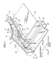
- Fig. 1 is a perspective view showing a rear vehicle body structure surrounding a rear floor, according to an embodiment of the present invention, specifically the structure of a right side of a vehicle traveling direction.
- Fig. 2 is an exploded perspective view of the rear vehicle body structure of Fig. 1.
- Fig. 3 is a schematic plan view seen from an arrow direction III in Fig. 1.
- Fig. 4 is a schematic sectional view taken along the line IV-IV of an arrow direction in Fig. 1.
- Fig. 5 is a schematic sectional view taken along the line V-V of an arrow direction in Fig. 1.
- An embodiment of the present invention will be explained below with reference to the drawings, wherein like members are designated by like reference characters. A rear vehicle body structure of a left side of a vehicle traveling direction is similar to that of a right side of the vehicle traveling direction of Fig. 1, and thus description thereof will be omitted.
- A rear wheel house 1 includes a wheel house inner 2 and a wheel house outer 3 (see Fig. 3). A
rear side member 4 is extended rearward from a front side of the rear wheel house 1 around an inner side of the rear wheel house 1 in a vehicle transverse direction. Therear side member 4 includes afront portion 5 disposed on the front side of the rear wheel house 1 to be extended in a vehicle longitudinal direction, a rear portion 6 disposed behind thefront portion 5 to be longitudinally extended along the transversely inner side, and an offset portion 7 positioned between the front andrear portions 5 and 6. A body side outer 24 is provided in the front from the rear wheel outer 3. - On a transversely inner side of a
bottom portion 8 of therear side member 4, a curvilinearupward wall portion 9 is longitudinally extending with its rear end offset transversely inside relative to its front end. Thefront portion 5 of therear side member 4 has an L-shaped section composed of thebottom portion 8 and thewall portion 9. The rear portion 6 of therear side member 4 has anupward wall portion 10 longitudinally extending along a transversely outer side of thebottom portion 8, which constitutes a U-shaped section of the rear portion 6 with thebottom portion 8 and thewall portion 9. In addition, the offset portion 7 includes a low upwardcurved wall portion 11 continuously provided between a transversely outer rear end of thefront portion 5 and a front end of thewall portion 10 formed on the transversely outer side of the rear portion 6. Thiscurved wall portion 11 has a shape corresponding to the shape of the wheel house inner 2, and is connected to a transversely inside of the wheel house inner 2. - On the front of the rear wheel house 1, a
side sill 12 is disposed so as to extend in a substantially straight manner in the vehicle longitudinal direction. Thisside sill 12 has a closed sectional structure composed of a side sill outer 13 and a side sill inner 14, thereby providing rigidity to a vehicle body side. Thefront portion 5 of therear side member 4 is connected to a transversely inside of a rear portion of the side sill inner 14. - On an upper portion of the rear portion of the side sill inner 14, a protruded
portion 15 gradually protrudes transversely inward from a main surface of the side sill inner 14 as it approaches rearward so as to be accommodated in a sectional inside of therear side member 4. This protrudedportion 15 is placed on thebottom portion 8 of therear side member 4, and arear floor 16 is placed on theprotruded portion 15. Therear floor 16 is connected onto thewall portion 9 on the transversely inner side of therear side member 4. A longitudinally extendingwall portion 17 provided on a transversely inner side of theprotruded portion 15 is positioned within width (or the sectional inside) of therear side member 4, and erected from thebottom portion 8 thereof to connect thebottom portion 8 with an undersurface of therear floor 16. Aflange portion 18 formed on a rear end of thewall portion 17 is connected to therear side member 4 at a vicinity of the transition point from thewall portion 10 to thecurved wall portion 11 and substantially on the same plane as that of thewall portion 17. Here, "substantially on the same plane" does not mean a plane strictly identical to that of thewall portion 17. It only means that theflange portion 18 needs to be continuous somewhat smoothly with thewall portion 17 and not be extremely bent. Accordingly, thewall portion 10 of therear side member 4 and thewall portion 17 of theprotruded portion 15 of the side sill inner 14 are interconnected by theflange portion 18, forming a curvilinear surface extending in the vehicle longitudinal direction. Then, a box-shaped closed sectional structure which is composed of the continuously connectedwall portions flange portion 18, thewall portion 9 of therear side member 4 disposed substantially in parallel to these, thebottom portion 8 of therear side member 4 and therear floor 16, is formed to have a longitudinally extending curvilinear shape with its rear end offset transversely inside relative to its front end . - An end of a
rear cross-member 19 extended in the vehicle transverse direction is connected to a front part of theprotruded portion 15 of the side sill inner 4. Thisrear cross-member 19 has a section bent in a crank shape. Therear floor 16 and acover portion 20 formed downward from its front end are connected to therear cross-member 19 to form a closedsection 21 along the vehicle transverse direction, thereby increasing vehicle body rigidity. - The sectional inside of the
rear side member 4 is partitioned into transversely inner and outer sides by thewall portion 17 of the protrudedportion 15. Inside the sections of the partitioned inner and outer sides, respectively, first andsecond reinforcements first reinforcement 22 has a shape of an upper side opened container with its bottom portion connected to thebottom portion 8 of therear side member 4. Anupward flange 22a on its transversely outer side is connected to thewall portion 17 of the protrudedportion 15. Anupward flange 22b on its transversely inner side is connected to thewall portion 9 of therear side member 4. Thesecond reinforcement 23 has, on its transversely inner side, anupward flange 23a connected to thewall portion 17 of theprotruded portion 15, and on its transversely outer side, adownward flange 23b connected to the main surface of the side sill inner 14. - According to the described embodiment, since the
wall portion 17 is accommodated within the sectional inside of therear side member 4 to connect thebottom portion 8 of therear side member 4 with therear floor 16, the geometric moment of inertia of therear side member 4 is increased. Theflange portion 18 formed on the rear end of thewall portion 17 is connected to therear side member 4 at the vicinity of the transition point from thewall portion 10 to thecurved wall portion 11, substantially on the same plane as thewall portion 17. Accordingly, the impact force F of a vehicle rear end collision can be smoothly transmitted from therear side member 4 to the side sill inner 14. Thus, a plate of therear side member 4 can be made thinner, reducing weight thereof, and providing excellent press formability. Especially, since theprotruded portion 15 of the side sill inner 14 has, on its transversely inner side, thewall portion 17 gradually extending transversely inward into the sectional inside of therear side member 4 and connected to therear side member 4 at the vicinity of thewall portion 10, the impact force F of the vehicle rear end collision can be smoothly transmitted from therear side member 4 to the side sill inner 14. - The first and
second reinforcements rear side member 4 and the bottom portion of the protrudedportion 15, and theupward flanges wall portion 17 interposed therebetween of the protrudedportion 15. Thus, suspension load input to the first andsecond reinforcements wall portion 17, enhancing the supporting rigidity of the rear suspension (not shown). - Furthermore, a two-component structure, i.e., the first and
second reinforcements second reinforcements upward flange 22b and thedownward flange 23b formed on the mutually separated ends of the first andsecond reinforcements wall portion 9 of therear side member 4 and the main surface of the side sill inner 14. Thus, suspension load is transmitted to thewall portion 9 of therear side member 4 and the main surface of the side sill inner 14, further enhancing the supporting rigidity of the rear suspension (not shown).
Claims (6)
- A rear vehicle body structure comprising:a rear side member (4) including,a front portion (5) in front of a rear wheel house (1), extending in a vehicle longitudinal direction,a middle portion (7) extending rearward from the front portion (5) around the rear wheel house (1), anda rear portion (6) extending rearward from the middle portion (7), and having a longitudinally extending first wall (10) on its transversely outer side;a longitudinally extending side sill inner (14), a rear portion of which is connected transversely outside the front portion (5) of the rear side member (4); anda rear floor (16) connected onto the rear side member (4) and the side sill inner (14),wherein the side sill inner (14) has a longitudinally extending second wall (17) accommodated within width of the rear side member (4) for connecting a bottom portion (8) of the rear side member (4) with the rear floor (16), and
wherein the second wall (17) is connected to the first wall (10) so that the first and second walls (10, 17) constitute a curvilinear surface extending in the vehicle longitudinal direction. - The rear vehicle body structure according to claim 1,
wherein a bottom portion (8) of the rear side member (4) continuously extends over the front portion (5), the middle portion (7) and the rear portion (6), and has a third wall (9) along a transversely inner side thereof substantially parallel with the curvilinear surface of the first and second walls (10, 17), and
wherein the curvilinear surface of the first and second walls (10, 17), the third wall (9), the bottom portion (8) of the rear side member (4) and the rear floor (16) cooperate to form a closed sectional structure extending in the vehicle longitudinal direction. - The rear vehicle body structure according to claim 1,
wherein the middle portion (7) of the rear side member (4) has a further wall (11) continuously provided from a front end of the first wall (10) of the rear portion (6) to a transversely outer rear end of the front portion (5), and
wherein the second wall (17) of the side sill inner (14) has, on its rear end, a flange portion (18) fixed to the rear side member (4) at a vicinity of a transition point from the first wall (10) to the further wall (11), on substantially the same plane as the second wall (17). - The rear vehicle body structure according to claim 3, wherein the side sill inner (14) includes a protruded portion (15) gradually protruded transversely inward from a main surface thereof as it approaches rearward, accommodated within width of the rear side member (4), and a transversely inner side of the protruded portion (15) constitutes the second wall (17) .
- The rear vehicle body structure according to claim 4, further comprising:a first reinforcement (22) positioned on transversely inner side of the second wall (17) of the side sill inner (14) and fixed to the bottom portion (8) of the rear side member (4), anda second reinforcement (23) positioned on transversely outer side of the second wall (17) of the side sill inner (14) and fixed to a bottom portion of the protruded portion (15),the first and second reinforcements (22, 23) having, on opposing sides thereof, flanges (22a, 23a) to be fixed to the second wall (17) interposed therebetween.
- The rear vehicle body structure according to claim 5, whereinthe first reinforcement (22) has, on its transversely inner side, the other flange (22b) to be fixed to a fourth wall (9) of the rear side member (4) longitudinally extending along a transversely inner side thereof, andthe second reinforcement (23) has, on its transversely outer side, the other flange (23b) to be fixed to the main surface of the side sill inner (14).
Applications Claiming Priority (2)
| Application Number | Priority Date | Filing Date | Title |
|---|---|---|---|
| JP2001317013 | 2001-10-15 | ||
| JP2001317013A JP3674571B2 (en) | 2001-10-15 | 2001-10-15 | Car body rear structure |
Publications (2)
| Publication Number | Publication Date |
|---|---|
| EP1302389A1 EP1302389A1 (en) | 2003-04-16 |
| EP1302389B1 true EP1302389B1 (en) | 2007-08-08 |
Family
ID=19134945
Family Applications (1)
| Application Number | Title | Priority Date | Filing Date |
|---|---|---|---|
| EP02256451A Expired - Lifetime EP1302389B1 (en) | 2001-10-15 | 2002-09-17 | Rear vehicle body structure |
Country Status (5)
| Country | Link |
|---|---|
| US (1) | US6672653B2 (en) |
| EP (1) | EP1302389B1 (en) |
| JP (1) | JP3674571B2 (en) |
| CN (2) | CN100465044C (en) |
| DE (1) | DE60221616T2 (en) |
Families Citing this family (27)
| Publication number | Priority date | Publication date | Assignee | Title |
|---|---|---|---|---|
| DE10060784B4 (en) * | 2000-12-07 | 2006-03-16 | Ise Innomotive Systems Europe Gmbh | Rear module for passenger vehicles |
| JP4168812B2 (en) * | 2003-04-07 | 2008-10-22 | 三菱自動車工業株式会社 | Connecting structure at the rear of the car body |
| JP4352769B2 (en) * | 2003-06-11 | 2009-10-28 | マツダ株式会社 | Lower body structure of automobile |
| JP4421380B2 (en) * | 2004-06-01 | 2010-02-24 | 本田技研工業株式会社 | Body frame structure |
| JP4413731B2 (en) * | 2004-09-28 | 2010-02-10 | 本田技研工業株式会社 | Side sill garnish |
| US7322640B2 (en) * | 2004-10-08 | 2008-01-29 | General Motors Corporation | Hydroformed and roll-formed cross sill assembly for vehicles and method of making same |
| JP4404036B2 (en) * | 2005-09-21 | 2010-01-27 | トヨタ自動車株式会社 | Vehicle rear structure |
| JP4815979B2 (en) * | 2005-10-05 | 2011-11-16 | マツダ株式会社 | Lower body structure of automobile |
| JP4654917B2 (en) * | 2006-01-12 | 2011-03-23 | 日産自動車株式会社 | Car body rear structure |
| JP4838604B2 (en) * | 2006-03-15 | 2011-12-14 | ダイハツ工業株式会社 | Rear side member structure of the vehicle |
| DE102007018167A1 (en) * | 2007-04-18 | 2008-10-23 | Dr. Ing. H.C. F. Porsche Aktiengesellschaft | Rear-side vehicle body structure |
| US7527327B2 (en) * | 2007-09-18 | 2009-05-05 | Ford Global Technologies, Llc | Rear vehicle subassembly having a towing hitch member |
| CN101835676A (en) * | 2007-10-24 | 2010-09-15 | 丰田自动车株式会社 | Structure for side portion of vehicle body |
| US7997618B2 (en) * | 2008-11-27 | 2011-08-16 | GM Global Technology Operations LLC | Rear frame for a motor vehicle |
| CN101665124B (en) * | 2009-09-24 | 2011-03-23 | 重庆长安汽车股份有限公司 | Rear floor margin plate of automobile |
| US8696051B2 (en) * | 2010-12-22 | 2014-04-15 | Tesla Motors, Inc. | System for absorbing and distributing side impact energy utilizing a side sill assembly with a collapsible sill insert |
| US20120161472A1 (en) | 2010-12-22 | 2012-06-28 | Tesla Motors, Inc. | System for Absorbing and Distributing Side Impact Energy Utilizing an Integrated Battery Pack |
| JP5337184B2 (en) * | 2011-03-04 | 2013-11-06 | 本田技研工業株式会社 | Car body rear structure |
| WO2013018417A1 (en) * | 2011-08-02 | 2013-02-07 | 本田技研工業株式会社 | Vehicle body rear structure |
| KR101326516B1 (en) * | 2012-03-02 | 2013-11-08 | 기아자동차주식회사 | Device for jointing rear side member and side sill of vehicle |
| KR101703586B1 (en) * | 2015-02-09 | 2017-02-07 | 현대자동차 주식회사 | Support structure of vehicle body |
| KR101724897B1 (en) * | 2015-09-10 | 2017-04-07 | 현대자동차주식회사 | Rear side member |
| FR3063709B1 (en) * | 2017-03-07 | 2019-06-07 | Renault S.A.S | BODY STRUCTURE OF A MOTOR VEHICLE. |
| JP7074039B2 (en) | 2018-12-06 | 2022-05-24 | トヨタ自動車株式会社 | Body structure |
| RU190334U1 (en) * | 2019-02-08 | 2019-06-26 | Публичное акционерное общество "АВТОВАЗ" | The design of the rear of the car body |
| CN121406886A (en) | 2020-01-03 | 2026-01-27 | 特斯拉公司 | Selective extraction of lithium from clay minerals |
| JP2023150062A (en) * | 2022-03-31 | 2023-10-16 | 本田技研工業株式会社 | Rear structure of vehicle body |
Family Cites Families (14)
| Publication number | Priority date | Publication date | Assignee | Title |
|---|---|---|---|---|
| US3528699A (en) * | 1968-12-11 | 1970-09-15 | Budd Co | Vehicle body side sill to rear sill transition structure |
| JPS5863168U (en) * | 1981-10-23 | 1983-04-27 | マツダ株式会社 | car body structure |
| JPS58128970A (en) * | 1982-01-27 | 1983-08-01 | Mazda Motor Corp | Construction of car body |
| JPS58133967A (en) * | 1982-02-04 | 1983-08-09 | Mazda Motor Corp | Rear body structure for vehicle |
| US4669776A (en) * | 1985-03-19 | 1987-06-02 | Mazda Motor Corporation | Front body construction for motor vehicle |
| DE4020363C2 (en) * | 1990-06-27 | 2000-11-30 | Opel Adam Ag | Side members for passenger cars |
| JP2978546B2 (en) * | 1990-09-20 | 1999-11-15 | マツダ株式会社 | Car rear body structure |
| JP3179187B2 (en) * | 1992-06-09 | 2001-06-25 | マツダ株式会社 | Car body structure |
| JP3206424B2 (en) * | 1996-03-25 | 2001-09-10 | トヨタ自動車株式会社 | Car body structure |
| JPH10297541A (en) * | 1997-04-23 | 1998-11-10 | Toyota Motor Corp | Rear underbody structure of vehicle |
| DE19811781B4 (en) * | 1998-03-18 | 2004-01-29 | Daimlerchrysler Ag | body structure |
| JP3518397B2 (en) | 1999-03-09 | 2004-04-12 | 日産自動車株式会社 | Body structure |
| JP2001247056A (en) * | 2000-03-08 | 2001-09-11 | Nissan Motor Co Ltd | Body rear structure |
| JP2001317013A (en) | 2000-05-10 | 2001-11-16 | Shimizu Corp | Mobile scaffold for segment erection |
-
2001
- 2001-10-15 JP JP2001317013A patent/JP3674571B2/en not_active Expired - Lifetime
-
2002
- 2002-09-17 EP EP02256451A patent/EP1302389B1/en not_active Expired - Lifetime
- 2002-09-17 DE DE60221616T patent/DE60221616T2/en not_active Expired - Lifetime
- 2002-10-11 CN CNB021468133A patent/CN100465044C/en not_active Expired - Lifetime
- 2002-10-11 US US10/268,679 patent/US6672653B2/en not_active Expired - Lifetime
- 2002-10-11 CN CN02252369U patent/CN2590828Y/en not_active Expired - Fee Related
Also Published As
| Publication number | Publication date |
|---|---|
| JP3674571B2 (en) | 2005-07-20 |
| JP2003118644A (en) | 2003-04-23 |
| DE60221616D1 (en) | 2007-09-20 |
| DE60221616T2 (en) | 2008-05-21 |
| US20030071490A1 (en) | 2003-04-17 |
| CN2590828Y (en) | 2003-12-10 |
| CN100465044C (en) | 2009-03-04 |
| CN1412062A (en) | 2003-04-23 |
| US6672653B2 (en) | 2004-01-06 |
| EP1302389A1 (en) | 2003-04-16 |
Similar Documents
| Publication | Publication Date | Title |
|---|---|---|
| US6672653B2 (en) | Rear vehicle body structure | |
| EP1808362B1 (en) | vehicle body | |
| EP1555191B1 (en) | Impact energy absorbing structure of vehicle frame member | |
| US8075047B2 (en) | Automotive vehicle body structure | |
| US7641270B2 (en) | Car body frame member | |
| CN100460264C (en) | Automobile side beam and automobile with same | |
| CN112109811B (en) | Vehicle body structure and vehicle comprising same | |
| JPH0820363A (en) | Body side sill structure | |
| CN102050151A (en) | Front vehicle body structure of a vehicle | |
| JP2006199132A (en) | Lower body structure | |
| JP3876279B2 (en) | Automobile pillar reinforcement structure | |
| US20200180703A1 (en) | Vehicle Body Structure | |
| JP2006297966A (en) | Body floor structure | |
| JP2019137352A (en) | Vehicle body structure | |
| JP2000095151A (en) | Rocker structure of vehicle | |
| JPH08119152A (en) | Car body structure | |
| EP1177968B1 (en) | Impact absorbing structure for car body front of automobile | |
| JP2004155393A (en) | Body front structure | |
| JPH08133131A (en) | Vehicle cross member structure | |
| JPH09207824A (en) | Lower body structure of vehicle | |
| JPH07232555A (en) | Door impact beam mounting structure | |
| JPH11192977A (en) | Body frame reinforcing structure for automobile | |
| US7165805B2 (en) | Vehicle front body structure | |
| JP4304449B2 (en) | Front body structure of the vehicle | |
| JP2001055163A (en) | Car body structure |
Legal Events
| Date | Code | Title | Description |
|---|---|---|---|
| PUAI | Public reference made under article 153(3) epc to a published international application that has entered the european phase |
Free format text: ORIGINAL CODE: 0009012 |
|
| 17P | Request for examination filed |
Effective date: 20021003 |
|
| AK | Designated contracting states |
Designated state(s): AT BE BG CH CY CZ DE DK EE ES FI FR GB GR IE IT LI LU MC NL PT SE SK TR |
|
| AX | Request for extension of the european patent |
Extension state: AL LT LV MK RO SI |
|
| RAP1 | Party data changed (applicant data changed or rights of an application transferred) |
Owner name: RENAULT S.A.S. Owner name: NISSAN MOTOR COMPANY, LIMITED |
|
| AKX | Designation fees paid |
Designated state(s): DE FR GB |
|
| GRAP | Despatch of communication of intention to grant a patent |
Free format text: ORIGINAL CODE: EPIDOSNIGR1 |
|
| GRAS | Grant fee paid |
Free format text: ORIGINAL CODE: EPIDOSNIGR3 |
|
| GRAA | (expected) grant |
Free format text: ORIGINAL CODE: 0009210 |
|
| AK | Designated contracting states |
Kind code of ref document: B1 Designated state(s): DE FR GB |
|
| REG | Reference to a national code |
Ref country code: GB Ref legal event code: FG4D |
|
| REF | Corresponds to: |
Ref document number: 60221616 Country of ref document: DE Date of ref document: 20070920 Kind code of ref document: P |
|
| ET | Fr: translation filed | ||
| PLBE | No opposition filed within time limit |
Free format text: ORIGINAL CODE: 0009261 |
|
| STAA | Information on the status of an ep patent application or granted ep patent |
Free format text: STATUS: NO OPPOSITION FILED WITHIN TIME LIMIT |
|
| 26N | No opposition filed |
Effective date: 20080509 |
|
| REG | Reference to a national code |
Ref country code: FR Ref legal event code: PLFP Year of fee payment: 15 |
|
| REG | Reference to a national code |
Ref country code: FR Ref legal event code: PLFP Year of fee payment: 16 |
|
| REG | Reference to a national code |
Ref country code: FR Ref legal event code: PLFP Year of fee payment: 17 |
|
| PGFP | Annual fee paid to national office [announced via postgrant information from national office to epo] |
Ref country code: FR Payment date: 20210812 Year of fee payment: 20 |
|
| PGFP | Annual fee paid to national office [announced via postgrant information from national office to epo] |
Ref country code: DE Payment date: 20210810 Year of fee payment: 20 Ref country code: GB Payment date: 20210811 Year of fee payment: 20 |
|
| REG | Reference to a national code |
Ref country code: DE Ref legal event code: R071 Ref document number: 60221616 Country of ref document: DE |
|
| REG | Reference to a national code |
Ref country code: GB Ref legal event code: PE20 Expiry date: 20220916 |
|
| PG25 | Lapsed in a contracting state [announced via postgrant information from national office to epo] |
Ref country code: GB Free format text: LAPSE BECAUSE OF EXPIRATION OF PROTECTION Effective date: 20220916 |